Printable Version of Topic
Click here to view this topic in its original format
Unmanned Spaceflight.com _ Private Missions _ IKAROS JAXA Solar Sail mission
Posted by: punkboi Mar 29 2010, 07:19 PM

Project Page: http://www.jaxa.jp/projects/sat/ikaros/index_e.html
Photos: http://jda.jaxa.jp/jda/p3_e.php?mode=level&time=N&genre=4&category=4064&mission=9095
Description Page: http://www.jspec.jaxa.jp/e/activity/ikaros.html
Posted by: pandaneko Apr 23 2010, 02:34 PM
Here is a movie about the Ikaros. It is a bit long, but it should give you some idea.
http://www.youtube.com/watch?v=7_6HOqBkP2o
Pandaneko
Posted by: punkboi May 8 2010, 07:36 AM
Akatsuki and IKAROS about to be transported to the VAB for mating to H-2A rocket
http://twitter.com/ikaroskun/status/13593614219
And here are photos showing the aluminum plates containing 63,248 names and a Planetary Society-provided DVD containing 89,000 names (that were submitted online between December of last year and March 22) being installed onto IKAROS

|
Posted by: JTN May 11 2010, 08:50 PM
(We don't seem to have a dedicated IKAROS thread, so...)
http://www.youtube.com/watch?v=7_6HOqBkP2o
In Japanese (which I can't understand), but that implies that a free-flying craft will be deployed from IKAROS just to take photos of the deployed sail. (Around 9:30.) K3wl.
Anyone know of an English-language (or translatable) resource that describes in detail what instruments/equipment (e.g., cameras, radios) are on board IKAROS? The http://www.jaxa.jp/countdown/f17/pdf/presskit_ikaros_e.pdf just mentioned is the best I've seen so far, but there's hints of stuff in the video that's not mentioned there (such as the aforementioned free-flyer).
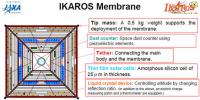
I'm impressed how much functionality they've crammed onto the sail itself -- it's not just a passive sail, it has solar cells, a dust counter, "liquid crystal device that controls attitude by changing light reflection characteristics", etc. Hope it all works.
Posted by: Juramike May 16 2010, 10:19 PM
JAXA set to launch a solar sail technology demonstration mission:
space.com article: http://www.space.com/businesstechnology/japan-venus-double-mission-100516.html
Posted by: Paolo May 31 2010, 05:08 PM
IKAROS has been spun up to 25 rpm in preparation for sail deployment within the next few days.
The counterweights that will draw out the sail masts have been deployed (see pictures in http://www.jspec.jaxa.jp/ikaros_channel/bn004.html
Posted by: akibow Jun 5 2010, 09:28 AM
Now(6/5 0:54 JST) IKAROS is drawing out the sail by the centrifugal force.
The sail is still bundled.
Please refer to the animation below URL.
The bundled sail has been extended to the opening drawing out passing about 10m.
It is a state of about 35 seconds of this animation now.
http://www.youtube.com/watch?v=7Mb47w0vB04&feature=related
Posted by: akibow Jun 6 2010, 02:28 PM
http://www.isas.jaxa.jp/home/IKAROS-blog/?itemid=549
----from IKAROS blog (japanese) , translated by akibow-----
Japan Aerospace Exploration Agency (JAXA) operated IKAROS (launched from Tanegashima Space Center on May 21, 2010(JST) until last night, and normally ended the second day of first-step of sale development.
However, there were some differences between the flight result and the simulation about development.
For more careful second development, we decided to examine the numerical value closely.
Therefore, the third day of first development and the second development is scheduled after Tuesday, June 8(JST).
We will announce schedule of the third day of first development and the second development as soon as we decides it.
The state of the explorer is excellent.
http://twitter.com/ikaroskun
----from IKAROS twitter (japanese) , translated by akibow-----
I'm telling many information to USUDA antenna.
They say that my movement is different from the simuration in pre-launch.
I am safe and energetic though movement seems to be different.

|
Posted by: nprev Jun 6 2010, 06:24 PM
Argh. Thanks very much, Akibow.
The IKAROS team is going about the deployment slowly & cautiously, and that's eminently sensible. It's gonna be done right!
Posted by: akibow Jun 6 2010, 11:41 PM
related article.
http://www.planetary.org/blog/article/00002527/
Posted by: akibow Jun 7 2010, 05:37 AM
http://www.isas.jaxa.jp/home/IKAROS-blog/?itemid=550
---translated by akibow---
TODAY'S IKAROS (6th,June)
IKAROS stands by with maintaing first development, length=5m or more.
Under this condition, the spin rate is increasing very slowly.
This is anxious for the developer of IKAROS , though is not an amount that becomes a problem.
it is the one about which it is anxious in a small symptom though it is not an amount that actually becomes a problem on because it is very slow.
The cause is not specified yet.
Many reasons are thought.
For instance, it is accelerated the rotation by the sunlight pressure like the pinwheel,
or an influence of the out gas or might be the one more by another factor.
We obsere this phenomenon by using this standby time. (Y)
6/6 IKAROS
Distance of the sun:1.04AU
Distance of the earth: 6,342,032km and right ascension =- 157.8° and celestial declinations =- 23.0°
Distance of Venus: 1.25AU
Posture: 7.4 rpm and spin rate = sun corner 15.0deg
Posted by: Paolo Jun 7 2010, 06:50 PM
my impression is that IKAROS, in its current semi-deployed status is just spinning up like a propeller due to solar radiation pressure, which in itself would be proof that the sail is working
Posted by: akibow Jun 8 2010, 07:38 AM
http://www.isas.jaxa.jp/home/IKAROS-blog/?itemid=551
---- summary ---
Japan Aerospace Exploration Agency (JAXA) will execute the third day of first developnent and the second development.
June 8th evening-midnight (JST) : 3rd day of 1st development + 2nd development
June 9th evening-midnight (JST) : confirm development
second development is full expansion of sail.
http://www.youtube.com/watch?v=7Mb47w0vB04...feature=related
Posted by: punkboi Jun 8 2010, 07:44 AM
Sail Deployment Schedule for IKAROS
(SUCCESSFUL) June 2 (Wednesday) evening - midnight: pre-deployment check sail (motor and commissioning)
(SUCCESSFUL) June 3 (Thursday) evening - the night: the early development of first stage sail deployment
(SUCCESSFUL) June 4 (Friday) evening - midnight: Day 2 Official first stage sail deployment
June 08 (Tuesday) evening - midnight: Day 3 Official second (and final) stage sail deployment
Tuesday, June 09 (Wednesday) evening - midnight: Review of second stage sail deployment
http://www.isas.jaxa.jp/home/IKAROS-blog/
Posted by: BrianJ Jun 8 2010, 03:21 PM
Another fascinating mission from JAXA :-) Hope it all goes well.
Can anyone tell me if it is planned to put IKAROS into orbit around Venus? Is it possible?
Or will there be a flyby?
Is there any information available about how much force/acceleration the sail experiences due to solar wind and radiation pressure?
Thanks and regards,
Brian
Posted by: ngunn Jun 8 2010, 03:28 PM
See here for an interesting idea
http://www.unmannedspaceflight.com/index.php?showtopic=6508&view=findpost&p=160641
Posted by: Norm Hartnett Jun 8 2010, 04:41 PM
Can anyone tell me if it is planned to put IKAROS into orbit around Venus? Is it possible?
Or will there be a flyby?
Is there any information available about how much force/acceleration the sail experiences due to solar wind and radiation pressure?
Thanks and regards,
Brian
Brian, the only info I've found is from http://en.wikipedia.org/wiki/IKAROS which states "IKAROS will unfurl its sail several weeks after launch, then will spend six months traveling to Venus, and then will begin a three-year journey to the far side of the Sun." Their source was an article in the The Guardian Weekly http://www.guardian.co.uk/world/2010/may/17/space-yacht-ikaros-japan-venus.
The Guardian article contains several errors so I'm not sure of its validity.
Posted by: punkboi Jun 8 2010, 06:10 PM
Believe it or not, the Guardian is correct. 
IKAROS will deploy a small free-floating camera once its solar sail completely deploys (which hopefully already happened) to photograph the spacecraft in all her diamond-shaped (or square-shaped, depending on your POV) beauty... I gotta check online to see if it has a second camera onboard that it could deploy once it reaches Venus.
To have a wide shot of IKAROS in deep space, with Venus in the background would be one of the coolest space images, ever.
Posted by: elakdawalla Jun 8 2010, 06:32 PM
Lou said in an http://planetary.org/blog/article/00002523/ that IKAROS does have two deployable cameras. I assumed both would be used right away to observe the sail after deployment. How close will IKAROS actually get to Venus? Any camera with a wide enough FOV to take in the deployed sail would probably only see Venus as a pretty small (and unbearably bright) light source, right?
Posted by: ugordan Jun 8 2010, 06:46 PM
Yup, particularly the unbearably bright part. Remember the automatic exposure control on LCROSS' live camera and the Moon isn't even that bright.
Posted by: Norm Hartnett Jun 8 2010, 07:04 PM
I suspect that it will depend on how steerable the craft turns out to be. It is an incredibly sexy space craft, using the solar sail for both power generation via the integrated thin film solar cells and for steering via integrated LCD panels to produce variable light pressure.
Edit; that's right, I saw the comment about IKAEOS' future in Lou's post and couldn't remember the link.
Posted by: Hungry4info Jun 8 2010, 07:53 PM
Not sure how to interpret it, but at the IKAROS twitter (translated with Google translator), IKAROS reports having been too tired to concentrate, and will try again tomorrow.
Posted by: elakdawalla Jun 8 2010, 08:16 PM
I saw that, but thought it just meant that it was the end of a long day of work. IKAROS only communicates through Usuda, so there's a window of time very late in the day Japan time when they do all their work. I interpreted that just as IKAROS signing off for the night.
That being said, I spoke with Lou Friedman on the phone a couple of hours ago and he said he wasn't sure they really commanded the final stage of deployment last night. I won't be really confident it happened until I see pictures.
Posted by: punkboi Jun 9 2010, 05:38 AM
Second stage sail deployment is scheduled to take place tomorrow...while IKAROS completed the full first stage deployment today
http://www.isas.jaxa.jp/home/IKAROS-blog/
Posted by: gilster Jun 9 2010, 01:30 PM
http://www.isas.jaxa.jp/home/IKAROS-blog/
It looks like full deployment of the boom structure was completed (i.e., first stage deployment), but from what I'm seeing on the IKAROS blog, the secondary deployment (the sail itself) should be ongoing. The most recent photo on the blog appears to show sail material.
Posted by: Norm Hartnett Jun 9 2010, 01:31 PM
Hum, the latest (6/9 @ 17:33) post on the blog indicates a fouled tether. (I think)
Posted by: gilster Jun 9 2010, 02:00 PM
I hope you're wrong, but that photo looks troubling to me, too.
Posted by: marsbug Jun 9 2010, 02:46 PM
The planetary society blog has a http://www.planetary.org/blog/article/00002536/.
Posted by: Norm Hartnett Jun 9 2010, 03:12 PM
Much nicer, my Google translation came out;
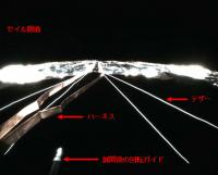
The image was deployed after the primary operation was conducted yesterday.
Strong sunlight, it looks a tether connecting the two overlap and sail body, the body close to the incident light in the shadows for the weak, the tether can see that reflected in the surface membrane and harness .
Hopefully elakdawalla's interpretation is correct.
Posted by: Hungry4info Jun 9 2010, 04:15 PM
A google translation of the most recent IKAROS blog post.
However, it is usual state of good IKAROS
Posted by: elakdawalla Jun 9 2010, 05:54 PM
Here's a much better translation of that photo caption, provided by Lionel Ward:
Posted by: Hungry4info Jun 10 2010, 09:15 PM
From the IKAROS blog via Google translator.
For more data, so once the report tomorrow, please wait a moment.
Posted by: Hungry4info Jun 11 2010, 03:28 AM
Success.
From the IKAROS blog.
Like) was launched from Tanegashima in the application of the IKAROS, June 3
Began to hoist the sail, the distance from the Earth about 770 million on October 6 km at the Sail
Stretched, and was confirmed by photovoltaic power generation.
Continue to measure the status of PV power generation patents or photon acceleration using a pressure
We demonstrate Bisoreniyoru orbit control, navigation through the acquisition of solar sail technology
For images, etc. We will also open more channels of specialized pursuit.
Images.
http://www.jaxa.jp/press/2010/06/20100611_ikaros_j.html#pict
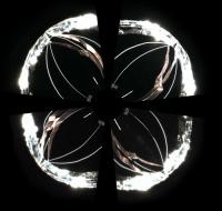
http://www.jspec.jaxa.jp/ikaros_channel/bn005.html
While the sail doesn't really look deployed from this awkward angle, remember these cameras are near edge-on with the sail and there is a large gap between IKAROS and its sail.
|
|
Posted by: nprev Jun 11 2010, 05:29 AM
Emily http://www.planetary.org/blog/article/00002541/ that the sail is fully deployed & IKAROS is power-positive; congratulations to the project and to JAXA!!!
This is truly historic; a pioneering first by any standard. Can hardly wait to hear how he (is IKAROS a he?) performs during his shakedown cruise!
Posted by: punkboi Jun 11 2010, 05:54 AM
All that needs to be done now is for IKAROS to deploy those two free-floating cameras and photograph the sail in all its beauty
Posted by: Astro0 Jun 11 2010, 11:41 AM
Can't wait for the images from the free floating cameras.
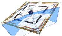
Looking at that diagram above, it looks like the deployment-view cameras overlap, but it's a bit hard to find anything to match up in each image.
Rather than fudge it, here's a foreshortened polar view created from the four sail-deploy images with no overlap attempted.
|
Posted by: punkboi Jun 12 2010, 06:19 PM
I hope they deploy that free-floating camera soon. Totally looking forward to seeing IKAROS in all its kite-shaped beauty
http://www.isas.jaxa.jp/home/IKAROS-blog/index.php?itemid=595
Posted by: Hungry4info Jun 13 2010, 05:10 AM
Anyone notice the IKAROS twitter profile pic keeps getting sadder and sadder? It's practically crying a flood now. Hilarously cute.
Posted by: nprev Jun 13 2010, 05:39 AM
Why would it be getting sadder? Is something not going well???
Posted by: punkboi Jun 13 2010, 05:43 AM
Maybe it's getting sadder 'cause it knows that brother Hayabusa most likely doesn't have any samples inside its capsule. I kid. 
Posted by: nprev Jun 13 2010, 06:02 AM
Mmm...close! According to my wife, the latest tweets are an imaginary conversation between IKAROS & Hayabusa (messages of encouragement for the latter.) Guess the tears are for Hayabusa-san's impending EOM.
Posted by: punkboi Jun 13 2010, 04:28 PM
IKAROS has stopped crying...while Akatsuki has been smiling the whole time. Must have had a beef with his older brother.
Posted by: punkboi Jun 14 2010, 07:51 AM
Looks like the first of two free-floating cameras (DCAM 2) will be deployed from IKAROS today
http://www.isas.jaxa.jp/home/IKAROS-blog/?itemid=629
And the IKAROS Twitter avatar is happy again.
Posted by: Spin0 Jun 14 2010, 08:45 AM
Seems free-floating DCAM2 has been released and the camera twitters here: http://twitter.com/DCAM2
Heh, Ikaros and DCAM2 are twittering about imaging.
Posted by: punkboi Jun 14 2010, 07:31 PM
Darn it. For some odd reason my Google toolbar won't automatically translate the DCAM2 Twitter page 
Posted by: Tom Tamlyn Jun 16 2010, 02:09 AM
Great picture of the fully deployed sail http://planetary.org/blog/article/00002552/ (in case there's anyone at umsf.com who doesn't check Emily's blog several times a day.)
Are there any specs on how long the camera is expected to remain within wireless range? And what's the plan for the second camera? I like punkboi's suggestion of "a wide shot of IKAROS in deep space, with Venus in the background."
TTT
Posted by: nprev Jun 16 2010, 02:18 AM
I've been wondering how long they'll stay near IKAROS as well. Also, do those things have some sort of attitude control? Can't figure out how they made sure that IKAROS stayed in the camera's FOV unless it was very precisely ejected.
Posted by: punkboi Jun 16 2010, 04:08 AM
Naw, the cameras don't have attitude control... They're gonna drift off into deep space after being released from IKAROS. Check out the Youtube link below... The DCAM floats off in a spiral fashion after it is ejected from IKAROS...which would explain why the spacecraft is off-center in the image (which I'll provide below...despite Tom helpfully providing a link to the TPS blog )
http://www.youtube.com/watch?v=7_6HOqBkP2o&feature=player_embedded
|
Posted by: nprev Jun 16 2010, 04:28 AM
Oh, okay, I get it now: The camera's actually spin-stabilized upon ejection. Thanks, PB!
Posted by: tolis Jun 16 2010, 03:01 PM
Hi Brian,
I am not involved with the project myself, so someone should confirm the following:
If IKAROS is following (more or less) the same trajectory as Akatsuki, then it is not possible to insert in orbit around Venus.
The problem is that, although solar sails can in principle affect "large" changes in their speed (DV), they cannot do so quickly.
They are a bit like ion drives in that respect: they thrust gradually but continuously. To go into orbit around a planet,
you would need to gradually modify the sail's orbit around the sun using the solar radiation pressure force (SRPF)
until it is essentially identical to the planet's. I would imagine that, SRPF being quite flimsy a force, that process will take many years.
By the same token, however, the sail should flyby Venus at around the same time as Akatsuki enters orbit, probably at a distance
of several hundred thousand km or more. It could also be maneuvered to encounter near-Earth objects (asteroids or comets)
although I imagine that, for now, the technology demonstration objectives take priority over any other activity.
Regards,
Tolis.
Posted by: Norm Hartnett Jun 16 2010, 03:48 PM
Hopefully some kind person here will be willing and able to explain how IKAROS is going to be able to maneuver using its LCD panels. I understand that by darkening and lightening the panels IKAROS can increase or decrease the light pressure (terminology?) thus increasing or decreasing its thrust in relation to the sun. I also understand that, depending on its angle in relation to the sun, it can either slow or accelerate in relation to its orbit. What I have a great deal of difficulty envisioning is how it can change its attitude, pitch and yaw if you will. Given that the satellite has to rotate to maintain rigidity how can the LCDs modify its angle to the sun? Can they modify its rotation rate?
|
Posted by: fredk Jun 16 2010, 05:37 PM
This is just a complete guess, but I would think that they could control the LCD panels on different sides of the sail independently. Darkening/lightening the panels on one side would provide a torque that presumably would change the orientation of the sail to the Sun.
Posted by: ugordan Jun 16 2010, 05:39 PM
Perhaps they plan to alternate the LCDs to on/off and time it depending on rotational rate so that always the same "side" of the spacecraft relative to the sun is dark. This would over time slowly nudge the rotational axis in one direction.
EDIT: fredk beat me to it!
Posted by: Schillrich Jun 16 2010, 05:45 PM
Hello,
I once found one abstract on the project page telling that it is indeed possible to change the rotation rate via the solar pressure on areas of the sail, or better that it will be part of the experiment to verify this technique. The idea behind that it not "simply" brightening and darkening of areas, but to switch between diffuse and specular reflection.
I also have one question (because the google translation of Japanese leaves me quite clueless):
Is there a difference between the 2 DCAMs (something about 'separate antennas' and 'only one has a receiver' comes out of google's translation attempts)? Has only one been deployed so far?
source: http://www.jspec.jaxa.jp/ikaros_channel/bn006.html
Posted by: Paolo Jun 16 2010, 05:58 PM
Is there a difference between the 2 DCAMs (something about 'separate antennas' and 'only one has a receiver' comes out of google's translation attempts)?
I think I understand that only DCAM1 has a receiving antenna on its housing on IKARUS, and DCAM2 uses that of DCAM1
Posted by: Schillrich Jun 16 2010, 06:03 PM
I also came to that conclusion. But would that mean both have been deployed?
Posted by: punkboi Jun 16 2010, 06:52 PM
IKAROS uses its thrusters to position the main spacecraft bus in a certain attitude...which in turn tugs on the tethers attached to the sail membrane and causes the membrane to be pulled and positioned into different angles. There's a computer animation of this towards the latter part of the video below
http://www.youtube.com/watch?v=7_6HOqBkP2o...player_embedded
Posted by: Norm Hartnett Jun 16 2010, 11:44 PM
Thanks punkboi, Schillrich, ugordan, and fredk, it becomes clearer to me now. IKAROS is a remarkably dynamic craft and I hope we get some detail on how its trip goes.

Posted by: punkboi Jun 17 2010, 06:27 PM
IKAROS' spin rate has decreased from 2.5 rpm to 1.1 rpm to allow better stability of the sail membrane as it gets tested for attitude control
http://www.isas.jaxa.jp/home/IKAROS-blog/
Posted by: Schillrich Jun 17 2010, 07:28 PM
Actually I understand it that way that it was decreased in order to allow attitude control experiments by reducing the angular momentum of the spinning craft.
Posted by: punkboi Jun 17 2010, 08:41 PM
Heh, that's what I meant. I worded it wrong
Posted by: punkboi Jun 18 2010, 06:43 PM
Hm. I thought DCAM1 was already jettisoned... I guess not
http://www.isas.jaxa.jp/home/IKAROS-blog/?itemid=646
Since IKAROS is spinning at only 1.1 rpm, I would assume the deployment of DCAM1 will be much more stable than that of DCAM2...and that IKAROS will be better framed (much more centered) in the DCAM1 images this time around
Posted by: BrianJ Jun 19 2010, 10:18 AM
Thanks ngunn, norm and Tolis (and everyone else) for the great info. Sending IKAROS to Apophis (via one or more flybys) is an interesting idea. I have a hunch that it could be possible for an IKAROS type spacecraft to be captured by Venus or maybe Mercury (solar sails work better closer to the sun - not so good for outer solar system). Someone must have studied this possibility, I'll see what I can google. It would also be interesting to get some idea of the numbers involved regarding possible acceleration, dV, etc.
The complexities involved with attitude control of a (slowly) spin-stabilized flexible sail attached to a rigid "hub", using two different methods (hub thrusters / sail variable reflectivity), are fairly mind boggling. I can imagine the whole thing starting to "ripple" like a flag in the wind, or even just wrap itself up into a ball, if you don't do it right!
Amazing stuff.
Thanks and regards,
Brian
Posted by: Paolo Jun 20 2010, 11:14 AM
From what I understand of the Google translation of the IKAROS blog http://www.isas.jaxa.jp/home/IKAROS-blog/index.php?itemid=647 it appears that the second camera pod is released today. It is to be jettisoned at a slower relative speed (details of the separation system and separation speeds anyone?) to conduct a longer imaging session from a closer distance.
Anybody knows also how long are the DCAM batteries supposed to last?
Posted by: djellison Jun 20 2010, 04:52 PM
I would imagine the batteries last far longer than the RF link budget between DCAM and IKAROS can last.
Posted by: punkboi Jun 20 2010, 05:25 PM
A previous IKAROS blog stated that the DCAM batteries...at least the one for DCAM2...is designed to last 15 minutes
Posted by: brellis Jun 21 2010, 02:47 AM
15 minutes of fame 
Posted by: Paolo Jun 21 2010, 04:51 PM
First picture from DCAM1 released! http://www.jspec.jaxa.jp/ikaros_channel/bn007.html
from much closer to IKAROS than DCAM2
Posted by: Norm Hartnett Jun 22 2010, 01:32 AM
According to today's blog post (6/22) they are adjusting the spin rate to "The spin rate will be selected to operate at optimum balance with light pressure" and they are seeking the optimum spin rate (now at 1.4 rpm). Also the GAP experiment is being activated under the charge of Kanazawa University.
Posted by: punkboi Jun 28 2010, 08:17 AM
DCAM1 images finally released
http://www.jspec.jaxa.jp/ikaros_channel/bn009.html
Posted by: pandaneko Jun 30 2010, 01:53 PM
TTT
I am not very surprised about this. About 15,16 years ago I was chatting to a prof at ISAS about the anntena opeinng of Halca space intereferometry satellite and asked him about the possibility. He simply flatly said that he would be extremely surprised if it did open up.
Apparently, he had seen it fully opended up at Mitsubishi's kamakura factory and never believed it will open up in space, but it did...
Second generation is going up in 2012, and what follows is some info on that.
http://www.jaxa.jp/pr/brochure/pdf/04/sat24.pdf
Of course, opening mechanisms must be different, I think. Halca anntena was built of very fine metal mesh, as I remember. Ikaros anntena must have been a lot easier to open up, I think. After all, it is a membrane, not a metal mesh.
Pandaneko
Posted by: JimOberg Jul 2 2010, 02:40 PM
To continue this line of thought:
What is the possible ultimate fate of Ikaros? Is there a maximum communications range?
Can the inspection camera be also used to image asteroids or comets during a fly-by five or ten years from now, or are they only in the jettisoned pods?? We can still do radio occultation science.
Can it achieve solar system escape velocity?
Posted by: gwiz Jul 3 2010, 09:39 AM
What is the possible ultimate fate of Ikaros? Is there a maximum communications range?
Can the inspection camera be also used to image asteroids or comets during a fly-by five or ten years from now, or are they only in the jettisoned pods?? We can still do radio occultation science.
Can it achieve solar system escape velocity?
From the images I've seen, the on-board cameras are wide-angle, not suitable for distant objects.
Posted by: punkboi Jul 9 2010, 07:12 PM
http://www.jaxa.jp/index_e.html
July 9, 2010 Updated
IKAROS: Acceleration by solar sail confirmed
The small solar power sail demonstrator "IKAROS," which successfully deployed its solar sail, was confirmed to accelerate by solar sail receiving solar pressure.
This proved that the IKAROS has generated the biggest acceleration through photon during interplanetary flight in history.
Posted by: elakdawalla Jul 9 2010, 07:26 PM
There's much more info in the http://translate.google.com/translate?js=y&prev=_t&hl=en&ie=UTF-8&layout=1&eotf=1&u=http%3A%2F%2Fwww.jaxa.jp%2Fpress%2F2010%2F07%2F20100709_ikaros_j.html&sl=ja&tl=en (Google translate link)
Posted by: Paolo Jul 13 2010, 11:46 AM
At last a release in English: http://www.jaxa.jp/press/2010/07/20100709_ikaros_e.html
Posted by: Paolo Jul 14 2010, 08:54 AM
Meanwhile, IKAROS is also doing some science. http://www.jaxa.jp/press/2010/07/20100714_ikaros_j.html(in Japanese) about the first gamma-ray burst detection
Posted by: Norm Hartnett Jul 19 2010, 01:18 AM
Some gems about the possible future of IKAROS from The Mainichi Daily News http://mdn.mainichi.jp/mdnnews/news/20100718p2a00m0na012000c.html
Posted by: Paolo Jul 23 2010, 05:18 AM
Apparently the solar radiation pressure attitude control experiment was successful! we have a true solar sail out there!
release (in Japanese only at the moment): http://www.jaxa.jp/press/2010/07/20100723_ikaros_j.html
Posted by: Norm Hartnett Jul 31 2010, 06:30 PM
Solar Distance : 1.05AU
Earth Distance : 26105537km, ascension =- 141.2 °, declination =- 26.2 °
Venus Distance : 0.75AU
Attitude : spin rate = 1.5rpm, sun angle 22.4deg
For the last few days IKAROS was spun back down and the solar angle increased as JAXA continues to investigate sail trimming. Experiments in ranging are on going and increased emphisis is being given to acceleration. Since the 24th of July all attitude control is being handled by the RCD (LCD panels), a truely stunning breakthrough in propellantless deep space navigation.
Posted by: punkboi Aug 26 2010, 07:51 AM
According to this animated image, IKAROS will arrive at Venus on December 18 (Japan time)...11 days after Akatsuki does
http://twitpic.com/2g57yr/full
Posted by: Norm Hartnett Aug 27 2010, 01:34 AM
8 / 26 IKAROS
Solar Distance : 1.00AU
Earth Distance : 31401035km, ascension =- 130.8 °, declination =- 28.0 °
Venus Distance : 0.48AU
Attitude : spin rate = 1.3rpm, sun angle = 26.0deg
IKAROS has crossed Earth's orbit and is headed Sunward. The last few weeks have seen experiments with rotation rates going up to 2.0rpm and back down and sun angles reaching as high as 32.2 degrees.
From punkboi's post above it appears that IKAROS will be passing Venus on the "outside" as would be expected since it has been increasing its orbital speed since deployment.
Posted by: Norm Hartnett Sep 9 2010, 07:00 PM

IKAROS to the upper surface of the earth is soon found success with . (Y)
9 / 9 IKAROS
Solar Distance : 0.96AU
Earth Distance : 32181854km, ascension =- 126.3 °, declination =- 28.5 °
Venus Distance : 0.35AU
Attitude : spin rate = 1.4rpm, sun angle = 29.9deg
I think this means that due to the angle of IKAROS vs location of the Earth IKAROS is losing com. Also they seem to be having troubles at their ground stations. I have seen no comments on when they expect to regain communications.
Does anyone (Emily?) have any further information?
Posted by: elakdawalla Sep 9 2010, 07:06 PM
I actually just sent an email to a Japanese contact about this today. I can't quite figure out what these updates mean. I'll post a blog entry if I learn anything.
Posted by: elakdawalla Sep 9 2010, 10:22 PM
Aha, it's not as bad as it seems. The problem is that Earth is passing through the sail plane, which is apparently a blind horizon for radio comms. Once Earth has gone through the sail plane to the other side, comms should resume. Today, Earth is within 13 degrees of the sail plane. IKAROS is being configured for autonomous operation during the communications blackout.
Posted by: Norm Hartnett Sep 10 2010, 05:50 AM
Thanks Ms. E.
I was pretty sure that things weren't as bad as my worry wart self  thought but my confident self just could not sort out the good data from the noise.
(Nice rant today BTW)
Posted by: Norm Hartnett Sep 19 2010, 05:03 PM
While the folks running IKAROS were acting fairly confident about the four day communications blackout, their relief and joy as IKAROS reestablished com was evident in the 9-18 Blog entry. http://www.isas.jaxa.jp/home/IKAROS-blog/?blogid=12

9 / 18 IKAROS
Solar Distance : 0.94AU
Earth Distance : 31844918km, ascension =- 124.5 °, declination =- 28.5 °
Venus Distance : 0.34AU
Attitude : spin rate = 1.3rpm, sun angle = 29.0deg
Posted by: Paolo Oct 10 2010, 04:11 PM
The October issue of the French magazine "l'Astronomie" (http://www.saf-lastronomie.com/revue/index.html) has a very interesting article on a French radio-ham who managed to receive the signal from Ikaros during June using a 3.5 m parabola.
unfortunately I don't have a scanner at hand...
Posted by: djellison Oct 10 2010, 04:57 PM
Good old Amatuer DSN guys. There's a ham radio group in Germany with a dish that would rival the smaller dishes of the DSN itself.
Posted by: Paolo Oct 11 2010, 05:35 PM
A report by the French radio ham is http://f1ehn.pagesperso-orange.fr/pages_radioastro/Images_Docs/IKAROS.pdf
Posted by: Norm Hartnett Oct 18 2010, 04:04 PM
IKAROS has spin up today. This is a very long time 2rpm.
A high spin rate, increasing the spin stiffness (as a frame) in space
Try to maintain a constant attitude.
Conversely a low spin rate will be strongly influenced by movements of the solar light pressure.
Adjusting the spin rate means that a balance of both to take advantage of this
I can do to change the direction of the desired position.
The IKAROS 10/18
Solar Distance: 0.84AU
Earth Distance: 28891627km, RA =- 132.6 °, declination =- 23.5 °
Venus Distance: 0.11AU
Attitude: spin rate = 2.1rpm, sun angle = 4.3deg
(Earth Distance 0.19AU)
Sun angle has been decreasing for several weeks now I wonder if they are "coming about" and reversing the "thrust" vector? One of the animations I saw seemed to indicate that might happen as they approached Venus.
Posted by: Norm Hartnett Nov 5 2010, 05:06 PM
The IKAROS 11/05
Sun Distance: 0.77AU
Earth Distance: 33318160km (0.22AU), RA=-146.5deg, Dec=-15.3deg
Venus Distance: 0.06AU (8975880km)
Attitude: Spin Rate=1.7rpm, Sun Angle=16.4deg
Blog entries are becoming sparser and apparently there are fewer communications periods as JAXA increasingly focuses on the Akatsuki Venus mission.
Posted by: Paolo Dec 12 2010, 10:05 PM
while Akatsuki was being recovered, IKAROS also flew by Venus last 8 December, some 80,000 km away
http://www.isas.jaxa.jp/home/IKAROS-blog/index.php?itemid=786
Posted by: punkboi Dec 13 2010, 02:19 AM
Interesting... I thought IKAROS wasn't suppose to pass by Venus till December 18
Posted by: pandaneko Jan 24 2011, 02:19 PM
I am posing a very stupid question, I think...
Akatsuki has sped by Venus, right?, and IKAROS has done that, too? That means they are going in the same general direction. My question is this. Can they not direct IKAROS to Akatsuki and take a look at Akatsuki's nozzle skirt? After all, we have another 5 to 6 years.
As I am not sure as to what IKAROS's ultimate goal, I just thought that it can get closer and closer to Akatsuki. Does it have a telephoto lens, bet not...
With future missions we do need engineering cameras!!!
Pandaneko
Posted by: gwiz Jan 24 2011, 03:04 PM
They passed Venus at very different distances, which means that IKAROS (80000 km) would have been less deflected by the gravity of Venus during the fly-by than Akatsuki (600 km). Add to that that Akatsuki also performed the incomplete injection burn as it passed the planet. As a result, the two would have been on rapidly diverging trajectories after the Venus encounters.
Posted by: Gsnorgathon Jan 24 2011, 08:45 PM
In addition, Ikaros has only engineering cameras designed to monitor sail deployment. They're pretty low-res, and have a very wide field of view that would make getting a good view of Akatsuki very difficult. The danger of a collision between the two spacecraft would be too high.
OTOH, the thought of Akatsuki taking a self-portrait as reflected in Ikaros's sails is truly delightful! But will have to stay just a thought, alas.
Posted by: Hungry4info Jan 24 2011, 11:25 PM
Akatsuki should cast a shadow, having IKAROS close by would allow something for that shadow to fall on. You could just image that shadow. I would figure it could be done at a greater separation than would allow for Akatsuki to image its reflection.
Posted by: djellison Jan 25 2011, 12:43 AM
You can't be serious H4I, Ikaros and Akatsuki are going to be thousands, probably millions of miles apart.
Posted by: Hungry4info Jan 25 2011, 01:31 AM
Oh I know. I thought it was understood we were just throwing ideas out there in a hypothetical situation.
Posted by: Gsnorgathon Jan 25 2011, 10:44 PM
I was thinking that it would make a great demonstration if Ikaros could be maneuvered to rendezvous with Akatsuki at some point during the next few years... but yeah: just tossing around hypotheticals.
Posted by: pandaneko Jan 26 2011, 12:51 PM
Before the demise of Akatsuki I was not terribly interested in this craft. I just thought of it as a planar object going around in space. Now, I just wonder, do they at JAXA know where it is going? Or, are they supposed to know where it is going?
With every other space craft people who sent them out there must have pre-determined flight plans for them to follow, including when the project is supposed to end. For instance, Prof Kawaguchi with Hayabusa, he apparently said he considers that the end of Hayabusa project is when international calls are invited later this year. That is simple and clear.
With this planar space craft I have not been able to find anything about its future whereabouts. I am just intrigued to know what is going on...By the way, there was an article in yesterday's Asahi newspaper about a space net that JAXA want to send up into near earth orbits in a few years time to capture space debris and burn them out with the net on destructive re-entry.
Pandaneko
Posted by: punkboi Jan 26 2011, 07:44 PM
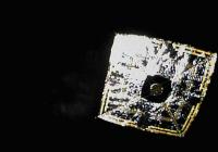
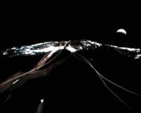
IKAROS took this self-portrait with Venus in the background! (Darn it, JAXA... Release a larger size of this image)
Thanks to Emily for the heads-up: http://www.planetary.org/blog/article/00002892/
Posted by: elakdawalla Jan 26 2011, 08:23 PM
Based on @ikaroskun's tweets I'm pretty sure this is the largest size available -- if I am translating correctly, it took days or weeks to even download thumbnail images at IKAROS' current distance from Earth.
Posted by: punkboi Jan 26 2011, 09:46 PM
Here's a larger version of the IKAROS-Venus pic...taken from the JAXA press kit
http://www.jaxa.jp/press/2011/01/20110126_sac_ikaros.pdf
|
Posted by: elakdawalla Jan 26 2011, 09:49 PM
Mine was taken from the press kit too -- I think yours has more pixels but is just upsampled. Which is not to say that upsampling to make the image occupy more space on the screen doesn't help in interpreting the image; I just don't think it actually contains any more data.
Posted by: pandaneko Jan 27 2011, 02:32 PM
I have always thought how lovely this child of yours is, whenever you posted something... It reminds me of my life with my own kids, who are all grown up by now. People go through life stages, I think... That apart, yes, you are right with your translation, the low bit rate transmission and all that.
I will translate the report you mentioned from tommorrow on as it does not seem to contain complicated pages, unlike those of Akatsuki. Why not? I myself want to know what has happened with this thing...
Pandaneko
Posted by: pandaneko Jan 30 2011, 02:26 PM
What is to follow from now for some time is my translation of IKAROS report.
This is a strange report, for a start, it does not have an outline page, and secondly, and here, I am simply guessing from one abbreviated character string printed at the top right corner of this report that this report was comissioned to one person at JAXA, Dr Osamu Mori, and thirdly, its refrence number is 4-2, perhaps suggesting that there are other reports that JAXA do not carry on their regulaer web pages.
Anyway, the first page, page 1 goes like this.
Comissioned report 4-2
Report on the termination of the regular operation of the small solar power sail engineering test spacecraft.
26 January 2011 (Wed)
JAXA
Dr Osamu Mori
P
Posted by: Paolo Jan 30 2011, 02:38 PM
can't wait to read the rest of the translation! many thanks in advance Pandaneko!
Posted by: pandaneko Jan 31 2011, 12:53 PM
Page 2: IKAROS report
0: Today's reporting items
We have been operating the small solar power sail engineering test spacecraft for the last 6 months, and we herewith confirm mission achievements based on the results so far and at the same time report on the latter part of the (continued) mission envisaged.
1: Mission objectives and significance
objectives
1.1 This is a front loading project for reducing the cost of development for the next project that we wish to run.
1.2 We wished to confirm the possibility of solar sailing and at the same time check on the power generation on the sail surface for the future hybrid propulsion system (no ion engines used this time)
IKAROS = Interplanetary Kite-craft Accelerated by Radiation Of the SunPage 2
P
Posted by: pandaneko Jan 31 2011, 01:20 PM
Page 3: IKAROS report 4-2
1. Mission objectives and significance
The following 4 items are the main objectives
1. Large membrane expanstion (objective 1)
1.1 Extend a large 20 m membrane using the mechanism (similar) to be used with future spacecraft under zero gravity and in vacuum
1.2 Evaluate the extension mechanism and the result of expansion and relate the obtained data to analysis model
2. Power generation using the power sail
2.1 Generate power with the thin film solar power generator and confirm power generation through on-the-membrane harness
2.2 Obtain data of the generated power and evaluate characteristics
3. confirm acceralation by the solar sail membrane and check the obtained data agains the actual orbital measurement data (distance change rate by distance measurement data) (objective 2)
3.1 (there is something here, but I cannot read it, P)
3.2 Evaluate the acceralation capability and reflect the result into the orbital caluculation methods for reaching the target astronomical objects
4. Obtain navigation techiniques by solar sail operation
4.1 Confirm orbit determination techniques under solar acceralation
4.2 Confirm active control methods of photon acceralation direction vector by sail manipulation under photon pressure and obtain navigation techniques using the rsult
Objective 1: minimum success
Objective 2: full success
P
Posted by: pandaneko Jan 31 2011, 01:49 PM
Page 4:
2: Result confirmation of mission requierments
(here, I do not wish to retranslate objectives carried before, so I will be brief with objective items as they are exactly the same, P)
2.1 Sail expansion:
complete, leading mass seperation on 26 May, primary expansion on 2-8 June, secondary expansion on 9 June and sail expansion was manitained after that by spin
2.2: evaluation
evaluation of spin and expansion and reflecting to expansion simlulation: achieved, we confirmed general agreenment between simulation and the real data obtained, and checked on the discrepancies and reflected them into the analytical model・. ,.
3: solar power generation
complete, on 10 June power generation was confirmed
3.1 interplanetary solar panell chracreristics evaluation, this was done once per week and compared with ground tested deterioration data<
HERE, I GIVE UP for this evening, because I thought that this page was a simple table page and that I could copy and paste and overwrite, but it is not that easy as its layout is messed up a lot. I will try again tommorrow.
P
Posted by: nprev Feb 1 2011, 02:07 AM
Pandaneko, by all means please take your time...and thank you for this!!!
Posted by: pandaneko Feb 1 2011, 01:11 PM
I will start from page 4 again. One thing that bothers me is that nowhere on this report submission it says submission was made to the Space Activities Comission (SAC) and the strange reference number, 4-2. I have a feeling that this is not an official report, rather internal, perhaps, and also interim, just to say, at this stage, something for the public at large.
Anyway,
Page 4 of the report 4-2 is as follows (this is a 30 page report)
2. Confirming results of the mission requests
1. Expansion of the large area membrane
1.1 Expand the 20 m (diagonal) membrane in vacuum and under zero gravity using the mechanism similar to that to be used with future space probes.
Completed: (I will come to definition at the end of this page, P)
Leading mas seperation on 26 May, primary expansion during 2-8 June, and final expansion on 9 June, and after that expansion was spin maintained
1.2 Evaluate expansion behaviour and expanded status and reflect the findings into the analytical model for expansion simulation.
Achieved: (I will come to definition at the end of this page, P)
We confirmed that observed expansion behaviour was more or less consistent with our prior simulation. We also evaluated discrepancies and refelected them into the analytical model.
2. (this 2 is within the header 2. that is, subsection 2, P) Power generation by the solar power sail
2.1 Generate power with the thin film solar power generation system, through the membrane harness, and confirm it by IKAROS itself
Completed:
power generation was confirmed on 10 June
2.2 Obtain relevant data of the solar cells on the membrane and grasp their characreristics
Achieved:
We conducted about once per week evaluation and compared the data with predicted deteriooration curve and grasped the characteristics
3. Confirm acceralation by the solar sail
3.1 Confirm solar sail's acceralation effects by orbit determination (measued distances and distance change rates)
Completed:
We observed photon induced acceralation and confirmed that the resultant propulsion was within the designed values.
3.2 Evaluate acceralation ability and reflect obtained data into the orbit determination methods for reaching target astronomical bodies
Achieved:
Optical characteristics were inorporated into the attitude orbital dynamics and established the optical method for parameter determination
and refelected those into the orbit planning system
4. Obtain navigation techniques with the solar sail
4.1 Confirm orbit determination techniques under photon induced acceralation
Achieved:
We have built a photon induced acceralation model and established the orbit detemining method including tracking, and actually operated the model with IKAROS.
4.2 Establish active control methods for photon induced vector treatment by the sail and the navigational techqniques by using those control methods
Achieved:
We confirmed that we can achieve required and planned orbit control by active sail attitude manoever. We conducted this relative to Venus and are satisfied with the results.
Glossary:
Achieved: mission requests jhave been more or less met and addtional analysis (including data from continued operation) may lead to further results
Completed: all of mission requests have been met perfectly
P
Posted by: pandaneko Feb 2 2011, 09:41 AM
Page 5:
2: operational procedures and confirmed results against mission requirements
(on the diagram) red blacket relates to the first few weeks in search of a minimum success, whch is the extention of the membrane and power generation and the blue bracket relates to the following 6 months in search of a full success, which is to verify the acceralation by the sail and to gain navigational skills
(Here, character strings are numbered from 1 to 5 and these are)
1. launch (21 May) and spin seperation of the craft (5 rpm)
2. initial checking and spin-up (25 rpm)
3. solar sail extension (2.5 rpm, 2-9 June), power generation on 10 June, and spin rate adjustment (1-2.5 rpm)
4. acceralation by the sail (9 July)
5. orbit control and navigation skills (December 2010)
Page 6:
2: Membrane extension (attitude data)
1. leading mas seperation on 26 May, primary extension during 2-8 June, and final extension on 6 June. Extension mechanism wroked well and spin behaviour was more or less consistent with expectation.
2. Departing camera was used on 14 and 19 June and captured the sail image and confirmed no anomaly.
(there are 3 graphs here, from left to right, and these are)
1. leading mas seperation
2. primary extension, and
3. start of final extension
With these graphs vertical axes on left are the spin rate around Z-axis, and that on the 3rd graph on the right is the angular velocity (red for X-axis and blue for Y-axis)
Page 7:
2: sail extension images
There are 6 images here, those on left were taken by the engineering camera on board and those two on the right were by the departing camera.
4 captions for the engineering camera, clockwise, are:
1. after leading mas seperation
2. during primary extension
3. after final extension
4. after primary extension
The caption for the departing camera images is "confirmation of liquid crystal device", ON is specular reflection and OFF is diffuse reflection
Page 8:
2: Power generation by the sail
We conducted a verification test on 10 June, followed by about once/week of characteristics evaluation and confirmed that the data was more less consistent with the predicted values obtained on the ground.
There is one table and one graph here on this page.
The header row for the table at top, from left to right says;
number, membrane section measued, Isc, Pmax, Imp, and temp
The second row has only one character string and that is the predicted value.
With the graph on right the caption on top is I-V characteristic.
These measurements were taken at 22:50 on 10 June, 2010, at 1.05 AU, earth distance of 7860133 km, sun angle at 13 deg, spin rate at 2.5 rpm.
Pandaneko
Posted by: pandaneko Feb 3 2011, 10:21 AM
Page 9:
2: Verification of photon acceralation
2.1 We confirmed photon acceralation by Doppler measurements.
2.2 Estimated propulsive power was in agreenment with the designed value.
2.3 We measured photon proplusion at different AUs and at different sun angles. Cumulative photon acceralation reached 100 m/s.
(2 graphs here)
One on left is the Doppler measurement history.
Vertical axis on left is the difference of IKAROS between two cases where photon pressure is present (actual measued values) and where photon pressure is absent (calculated values) in mm/s.
Horizontal axis is the time line around the final extension on 9 June 2010.
The caption at the bottom of this particular graph says "Estimated (from Doppler effects) photon pressure= 1.1 nM"
There are chrracter strings on this graph, top one says "execution of final extension at 09:36 UTC" and the one below it says "time region where data is missing due to swtich over to oneway Doppler mode".
The other graph on the right is the cumulative photon acceralation, vertical axis on left is just that, horizontal axis is the time line between 22 May and 8 December. The caption at bottom of this graph says "We achieved 100 m/s by November".
Page 10:
2: Navigational skills obtained with the solar sail
2.1 With the liquid crystal device we conducted device checking and attitude control experiment and confirmed that expected control ability was achieved.
2.2 IKAROS flew by Venus at 80,000 km on 8 December and it was a day later than AKATSUKI because we conducted a non-balistic flight by the solar sail on way. Akatsuki was led to the sun side of Venus and IKAROS to the night side.
(with this page 10, we have 2 graphs and one image)
With the leftmost graph the vertical axis is the sun angle (its title is the spin rate during control mode, by the way) and the horizontal axis is the time line in UST, starting at 12:00 on 12 July.
The character string in the top box is "control start", bule dots are before the start of control mode and red dots are taken during this control mode operation. Solid line is the expected sun angle without control.
The chenck of caption below it says" gievn the initial evaluation which took into account the sun distance and the sun angle we confirmed that over 90% of attitude control accuracy was achieved".
The second graph is as follows.
The character string in red at top says "nearest approach to Venus at 07:39 UT and IKAROS is moving to the left.
Then, the image, and this is before image processing.
(To me, it does not look fully extended. It looks like a dried jelly fish thrown up on a beach..., P)
Page 11:
3: Outline of follow-up operations
3.1 duration: until about end March 2012 (and we will be making a decision on further follow-up operation at that time)
3.2 DSN station: Usuda 64 m
3.3 Objectives:
We wish to gain further insight into solar sail navigation which we hope will contribute to the development of next project.
3.3.1 Solar power sail mission: 4 new themes and 3 continuing themes
3.3.2 With optional devices (GAP, ALDN, VLBI) current mission will continue
3.3.3 Evaluation of newly developped devices, such as liquid/gas equilibrium thruster, MGA, mission system electicity
PANDANEKO
Posted by: pandaneko Feb 5 2011, 09:37 AM
Page 13:
3: Continued mission plan (themes related to the main mission)
3.1: large membrane extension
Continuation theme 1:
Evaluate the extended state and check up on mechanical deterioration of the sail surface
New theme 1:
Proactively pull out the membrane behavoiur and shape changes and construct a dynamic model of the extendes state
3.2: Power generation
Continuation theme 2:
evaluate the capacity and monitor system deterioration
3.3: Verification of acceralation by the sail
Continuation theme 3:
Evaluate its ability and dependency on reflection characteristics and deterioration, and attitude dependecy on membrane shape during photon acceralation
New theme 2:
Improve, given membrane shape changes, the the seperation accuracy of photon reflection and areas concerend, and use the data to construct an optical parameter model of the membrane
3.4: Navigational skills:
New theme 3:
Make use of the increasing distance between Earth and IKAROS, to evaluate the orbit determination accuracy under photon pressure andacceralation
New theme 4:
Evaluate the long term control/guidance characteristics per each orbit revolution
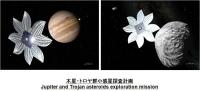
NOTE 1: With all of these themes they are expected to be completed by 31 March 2012, and contribute to the next step in development for the project targetted at Jupitor and the Troia group of asteriods
NOTE 2: Mission included in the continuation plan should contribute to the studies of large membranes, orbit determination/control under solar photons. These will be useful for other purposes and projects.
Page 13:
3: Comments on new themes included in the continued operation
New themes 1 and 2:
These should contribute to the studies of large membrane structure.
We confirmed, from regular operation so far, that changes in sun angle and spin rate will lead to membrane shape changes and that solar photon pressure does contribute to membrane behavoiur.
With this in mind, we will proactively alter the combination of sun angle and spin rate in order to;
1. construct a dynamic model of the extended membrane structure
2. consttuct an optical parameter model of the membrane
New themes 3 and 4:
These will contribute to the studies of orbit determination and guidance under photon pressure.
Given increasing changes in the relative positions of Earth and IKAROS compared with those during the initial regular operation we will make use of them in order to;
1. evaluate orbit determination accuracy under photon acceralation (accuracy decreases as the distance increases)
2. Evaluate long term controlability (evaluate orbit info per every revolution around the sun)
P
Posted by: pandaneko Feb 6 2011, 09:29 AM
Page 14:
3: Orbit plan (from launch to Venus)
launch: 21 May 2010
nearest approach to Venus: 8 December 2010
(There are 2 graphs here and this page must be self-explanetary, P)
Caption at the top of the left graph says "Nearest approach to Venus on 8 December 2010", and the caption at bottom is "launch on 21 May 2010". At the centre is the sun, Venus green, earth blue.
Caption at the top of the right graph is "Sun-Earth fixed system". At the centre is the sun and Venus green, and the character string just below IKAROS (in red) is the Earth
Page 15:
3: Orbit plan (from nearest approach to Venus to the end of fiscal 2011)
Black square: nearest approach to Venus on 8 December 2010
Black diamond: 31 March 2012
(There are 2 graphs here)
With the left graph the sun is at the centre and the caption at the top is "nearest approach to Venus on 8 December 2010"
With the right graph the caption at the top is "Sun-Earth fixed system", sun at the centre, Earth is the blue dot on the right, IKAROS movement in red.
Page 16:
3: Orbit plan (from fiscal year end of 2011 to the furthest point)
black diamond: 31 March 2012
black star: 6 December 2012
(There are 2 graphs here)
2 captions at the bottom of the lefthand graph, the left one says "furthest point on 26 December 2012" and the one on the right says "31 March 2012".
With the right hand graph, my earlier comments apply.
Page 17:
3: Operational policy for the latter half of IKAROS operation
Given the limited coms capacity our operational policy is as follows:
3.1 February 2011:
attitude/orbit determination (new themes 3 and 4, continuation 3)
confirmation of sail extension and power generation (continuation 1 and 2)
GAP operation and reproduction of ALDN observation data
3.2 May, June 2011:
attitude/orbit determination (new themes 3 and 4, continuation 1 and 2)
confirmation of sail extension and power generation (continuation 1 and 2)
reproduction of GAP, ALDN data, engineering experiment with VLBI
attitude/orbit determination upon changing spin rate and sun angle (new themes 1 and 2)
3.3 July 2011 and beyond:
We will make our judgement based on the results obtained by June.
Current tentative plan is as follows:
We are going to change the spin rate and the sun angle over a very wide range and;
1. If we can improve coms status we will try a longer operation by economising on fuel.
2. If we cannot improve coms status asa result we will still try to economise on fuel and try to maintain MGA's link attitude.
P
Posted by: pandaneko Feb 8 2011, 08:56 AM
I now realise that I made a simple mistake with my earlier translation.
Page 17 should have been page 18. And Troia group of sateroids should have been Trojan group of asteroids, I think.
Anyway, page 17 should have been as follows, P
Page 17:
3: Latter mission operational plan
Continue with optional devices mission
1. GAP: GAP= GAmma‐ray burst Polarimeter
This device comprises of a refelector at the centre, surrounded by 12 pieces of fluorescent light detector, intended to measure polarisation of Ganma ray bursts.
2. ALLADDIN= Arrayed Large‐Area Dust Detector for INterplanetary Space
This device is intended to record collision occurence times, maximum signal value and signal decay so that data will contribute to spatial distribution analysis of space dusts in the region nearer to the sun than earth.
3. VLBI= Very Long Baseline Interferometry
This will make use of quasors in the far distance in order to measure precise IKAROS positions using delta VLBI technique. Regular measurements will be made with future missions.
Results so far of these optionnal devices:
1. GAP, ALDN, VLBI are all normal and producing data, however
2. because we concentrated our resources on system operation as the first priority we have not had enough time with these divices. So, our current intention is to use them as long as we could.
P
Posted by: pandaneko Feb 8 2011, 09:05 AM
Page 19:
4: Supplementary information
What is the solar sail?
1. Solar sail: is a craft which makes use of solar photons for propulsion.
2. Solar power sail: is, in addition to the sail membrane itself, solar power generation devices are attached to the sail surface
If we combine ion engines and solar power sails we should be able to navigate into regions much further away from the sun. We will be trying out this idea with our next mission targeted at the Trojan group of asteroids and Jupitor.
P
Posted by: pandaneko Feb 8 2011, 09:10 AM
Page 20:
4: Supplementary information
Significance of solar power sailing:
This is expected to lead to flexible operation of probes.
It is also expected to provide enough electrical power in the vicinity of Jupitor and beyond.
P
Posted by: pandaneko Feb 8 2011, 09:20 AM
Page 21:
There are graphs and other structures with this page, but they are self-explanetary. So, my translation is only about IKAROS specs, as follows.
Main body size: 1.6 m in diam. and height 0.8 m
Membrane size:s 20m by 20 m, and membrane thickess of 7.5μm
Mass: 308kg, of this 16kg is the membrane mass
Orbit: direct flight to Venus
Orbit determination: range fidings and Doppler measurements
Attitude control: by spin
Propulsion: vapour and liquid equilibrium thruster and gas jet thrusters
Mission duration: longer than 6 months
Comms: 2 LGAs and 1 MGA
P
Posted by: pandaneko Feb 9 2011, 09:03 AM
I will skip pages 22 and 23 as they are too obvious.
Page 24: Supplementary info on GAP
1. Small table header from left to right:
GRB name, trigger time, distance, alpha, beta, angle of entering, simultaneous observation
2. With the 3 graphs here vertical axis is intensity, horizonrtal time in seconds
Main text (jist of it) as follows:
GAP is a ganma ray burst polariser detector. It also achives simultaneous Compton scattering counting.
Power was switched one month after launch. Data is stored in memory and sent back to earth. No mulfunction to date. GAP detects polarisation of megnetic field.
P
Posted by: pandaneko Feb 9 2011, 09:24 AM
Page 25:
4: Supplementary info on GAP
(Here, I am only translating gists of what this page says, P)
Primary objective of GAP is to measure polarisation of ganma ray bursts and try to understand the mechanism. However, it is only 4 months in operation and we have not yet meaure enough of these bursts.
Following report (what follows?, P) is based on the collaborative work with all those GRB satellites around the world with a view to determining the directions of these bursts.
Earlier page's list has data from Russian Konus satellie (K), US Fermi satellite (F), and US-Italy Swift satellite (S). For example, the burst, GRB 100826A (detected on 26 August 2010) was determined to be within the region surrounded by the blue frame with the graph here. Due to polarisation measurements IKAROS is providing additional accuracy.
P
Posted by: pandaneko Feb 9 2011, 10:01 AM
Page 26:
4: Supplementary info on VLBI (multi tone transmitter)
Result of of experiments:
Succeeded in obtaining about 20 times more accuracy of orbit determination compared with earlier JAXA measurements (Hayabusa and AKATSUKI), with the thermal noise level of 50 pico seconds.
Objectives of the experiments:
This is a mission devoted to try out DDOR(Delta differential one-way range) techniques. Basically, very far radio emitting stars are used and the very long baseline interferrometry and triangulation is involved. Participants are as follows:
University of Tasmania: Hobart26m
DSN: DSS34 34m,DSS45 34m, DSS43 70m
ESA: Cebreros 35m New Norcia 35m
ATNF: Mopra 22m, ATCA 22m
Shanghai Observatory: Urmuchi 25m, Shanghai 25m, Konmei 40m
Japan, 32m, 34m, 34m and 64 m)
NASA JPL is quite active in this technology, and for instance, NASA DSN were deeply involved, when required, with DDOR determination of Akatsuki, almost everyday. Collaboration has been done before, but we lacked this essential element, multi tone transmitter, and this time we developped a dedicated transmitter and used it with 8 organisations' 15 antennas with 24 pases.
Comparison (orbit information) between Akatsuki and IKAROS data is as follows:
Akatsuki:
precision : (thermal noise) 700 pico seconds
accuracy : 1 to 2 nano seconds
IKAROS:
precision: (thermal noise) 50 pico seconds
accuracy: 50 to 150 pico seconds
This comparison was made around August 2010
P
Posted by: pandaneko Feb 10 2011, 10:08 AM
What follows from page 27 on, I find it very difficult to translate (technical terms, mainly), but I will give it a try in the belief that even if my translation is not good some people with background knowledge may find them useful.
Page 27:
4: Supplementary info on VLBI multitone transmitter
We developped a DDOR digital base band converter (64 Msps/16 ch/4 bit, 4096 Gbps). 2 graphs here, one on left is the result obtained by this digital wideband system, and one on right is the data recorded by conventional analogue/narrowband system.
With conventional recording system you need to combine a couple of 8 MHz bandwidth analogue signals. The right graph indicates that the gain and the phase within the band are not flat enough.
With this new system it becomes possible to use weak qasor signals as calibrators and that will be useful with future wideband DDOR systems using Ka band.
Page 28:
4: Supplementary info on VLBI multitone transmitter
There is one graph on this page, which came from the observation made on 29 July 2010, using Usuda-Canbera baseline for VLBI observation.
Vertical axis is the delay residual (whatever it means, P) in nano seconds. Horizontal axis is the time ellapse from the start of observation in seconds.
Upperleft character string says "Lizzard constellation's star BL's delay residual"
Character string down right says "delay residual of quasor J1425-2513"
Character string to the left os it in blue says "delta DOR observed quantity"
The bottommost character string says "IKAROS delay residual"
There are 2 texts here on this page, the first one being explanation of the chart itself, and the second one is on future operations from now on. And, I am now going to paste those text down here for further translation. If it does not go well, then I will send this up anyway and try to upload another post.
On the graph, 6 groups of dots (I find only 5, P) relate to IKAROS' VLBI delay residual and those 3 upper left and another 3 upper right exists in the vicinity of IKAROS on the "star sphere surface" (I do not know the word for this, P)
These two are the delay residuals of the astronomical bodies whose positions are accurately known. IKAROS' plot is based on range/Doppler measurements and if its orbit determination is correct IKAROS' delay residual should be on the same line as these of two astronomical bodies'.
However, these are not in line, clearly suggesting a bias coming from orbit determination error not accurately estimated by range/Doppler measuments.
ΔDOR observation quantity: (-7.83 ns±50ps)
With these two astronomical bodies we see that , despite weak signals from quasor producing a lot of noise, delay residuals are on the same line, suggesting that bias due to the presence of atmosphere etc has been successfully removed.
Operations from now on:
Compared with bus system antennas VLBI transmitter has a narrower bandwidth and future observation oppotunities are limited and measurment accuracy is not large. However, we will continue to operate the system because we expect to be using this system with our future missions a lot regularly and we need to improve on the system such as pipelining and semi-automatic operation.
Observation so far has given us a lot of quality data for orbit determination and we should be able to come up with detrmination accuracy of a few centimeters, compared with a few meters accuracy required for deep space orbit determination.
We will also be making use of near Earth satellites for further improvements on accurate orbit determination.
P
Posted by: pandaneko Feb 10 2011, 12:59 PM
Page 29:
4: Supplementary info on ALADDIN
ALADDIN = Arrayed Large Area Dust Detectors in INterplanetary space
Mission objectives:
Cosmic dusts detector engineering tests, to be used for future Jupiter exploration and other outer planets, also to be used in near Earth orbits.
Device composition and arrangement:
1. 0.3% of the sail membrane (0.54 square meters)
2. Piezo-electric thin film elements of 2 different thicknesses at 9/1000mm and 20/1000mm in 4 channel arrangement at the sensing part (ALDN-S at 40g) and detection part (ALDN-E at 210g)
P
Posted by: pandaneko Feb 10 2011, 01:11 PM
Page 30:
4: Supplementary info on ALLADIN
Operational results:
1. Operation started on 21 June 2010.
All 8 channels detected cosmic dusts, more than 100 of them within the duration of acumulative 25 days startong on 30 June.
2. Study of distance dependency of cosmic dusts in the solar system
We are getting more accurate data by cumulative 24 hours of observation.
(End of IKAROS report, 4-2)
P
Posted by: Paolo Feb 13 2011, 12:46 PM
domo arigato gozaimasu, Pandankeo, I have really enjoyed your translation!
I think they are referring to the quasar "BL Lacertae"
Posted by: pandaneko Feb 14 2011, 12:45 PM
Thanks, Paolo
I am taking a little time off at the moment, but I will come back with the newsletter translations soon.
Since it contains different topics and since I do not wish to be a new topic starter I am thinking how best I might do this. However, I can assure you that these newsletters do make some interesting light readings.
While at work I always enjoyed these, and I would have thought they no longer existed...
P
Posted by: Paolo Feb 14 2011, 06:02 PM
just one question: what are they talking about when speaking of "1970", "1990" etc in page 30?
Posted by: pandaneko Feb 16 2011, 09:26 AM
Thanks and apologies for not translating fully. You can actually ask for further translations any time you wish.
The top graph is cosmic dusts distribution in space nearer to the Sun than the Earth.
Vertical axis is the flux and the horizontal is heliocentric distance in AU.
Character string at the top left of this graph is IKAROS (2010), down below it in red is Helios 1 (1970's) and just to the right of it is the counting by Galileo (1990's).
Two characters at the bottom left is : Venus orbit, right : Earth orbit
There are two small graphs at the bottom and one on left is IKAROS orbit, and the one on the right is IKAROS orbit with respect to the Sun-Earth fixed frame of reference.
Here below, I will paste the main text and hope it will succeed.
Page 30: Supplementary information on ALDN
Operational results:
(1) Large area dust counter started operation on 21 June 2010. Dusts larger than a few micron size were recorded on all of the 8 channells. A little more than 100 dusts were counted during 25 days starting on 30 June and this number is larger than the count recorded by a German counter (MDC) on board NOZOMI during 45 months from August 1998.
(2) Study of dusts distribution dependence on heliocentric distance
Earlier countings during 1970's and 1990's were somewhat uncertain in accuracy in time resolution. IKAROS data seems to show a continuous rise in the flux as we approach Venus. We may get more information as we continute to operate IKAROS.
P
Posted by: pandaneko Feb 21 2011, 12:44 PM
I am taking a little time off at the moment, but I will come back with the newsletter translations soon.
Since it contains different topics and since I do not wish to be a new topic starter I am thinking how best I might do this. However, I can assure you that these newsletters do make some interesting light readings.
While at work I always enjoyed these, and I would have thought they no longer existed...
P
Paolo
I am afraid I am giving up the idea of translating this newsletter, simply because I found that I cannot copy texts. I have been trying for the last few days all of my tricks for copying, but to no avail.
If you or any other Forum collegues find something to be translated with any other items (as long as it is not too much) I will be willing to do so. I am a very fast translater (actually, very, very fast...) as long as I can copy and paste and overwrite.
Apologies once again and I will sit back for the moment and enjoy posts. My next main interest is ATRO-G, as it will not go far away from earth.
Pandaneko
Posted by: Paolo Jun 1 2011, 07:00 PM
a good resume of the IKAROS missions, its technologies and its results so far (in English)
http://www.isas.jaxa.jp/e/forefront/2011/tsuda/index.shtml
Posted by: stewjack Jun 2 2011, 12:03 AM
IKAROS had kinda fallen out of my brain! That article put it back in.
Thanks Paolo
Posted by: Paolo Jun 3 2011, 11:35 AM
Aviation Week is running more or less the same story: Jhttp://www.aviationweek.com/aw/generic/story_channel.jsp?channel=space&id=news/asd/2011/06/02/11.xml
Posted by: Norm Hartnett Jun 3 2011, 03:00 PM
Thanks Paolo! I saw the Aviation Week story and came directly here to see if anyone had a link to Yuichi Tsuda's paper and, as always, UMSF came through.
The sheer, simple elegance of this experimental spacecraft has always left me almost speechless. Integrating propulsion, power generation, attitude control, and science instrumentation into the sail was simply brilliant and a huge step beyond what any other solar sail experimental craft have been designed to do. I am so glad to see that JAXA and the IKAROS team have achieved all their goals and that so many of their concepts have been proven viable.
It is without a doubt the crowning achievement of JAXA to date IMO. It may well be the most important spacecraft of the last decade in terms of spacecraft propulsion and control. I look forward to their follow-on spacecraft that will build on this success and add an Ion engine.

|
Posted by: Paolo Oct 19 2011, 07:39 AM
Ikaros reversed its spin yesterday: http://www.jaxa.jp/projects/sat/ikaros/index_e.html
Posted by: Paolo Jan 6 2012, 11:07 AM
if I understand correctly today's release, IKAROS has been put into hibernation owing to the large distance from the Earth and Sun, making communication difficult and owing to the quasi-depletion of its reserves of gas for attitude control
http://www.jspec.jaxa.jp/ikaros_channel/bn018.html
pandaneko, can you confirm?
Posted by: pandaneko Jan 19 2012, 08:50 AM
http://www.jspec.jaxa.jp/ikaros_channel/bn018.html
pandaneko, can you confirm?
Yes, Paolo, but not in one go、I am afraid. I will translate the whole lot in parts. First, the introduction.
Updated 6 January 2012.
About the result of reverse spin operation of IKAROS and transfer into heybernation mode
We have been analysing the result of above reverse spin operation carried out on 18 October 2011 and we are now able to offer detailed information about this reverse spinning.
Also, we are informing you that we have confirmed that IKAROS has entered into a hybernation mode, and this is judged from the operation records up until now, by 6 January 2012 (instruments shut down because of the decrease in the power generated).
◆ Result of the reverse spin operation
On 18 October 2011 IKAROS sfifted into the reverse spin status without any hitches. Its data is carried on the table 1 as follows.
P
Posted by: Paolo Jan 19 2012, 09:25 AM
thanks pandaneko. there is also an English release at http://www.jaxa.jp/projects/sat/ikaros/index_e.html but it seems to lack some of the details of the Japanese version
Posted by: pandaneko Jan 20 2012, 09:40 AM
The table in question is a regular matrix, 3 columns and 7 rows. Members are as follows.
C1R1: Item of evaluation.
C2R1: Before reverse spin operation
C3R1: After reverse spin operation
C1R2: Spin rates
C2R2: 0.17 rpm
C3R2: - 0.24 rpm
C1R3: Spin rate changes
C2R3: about 0.1 rpm (decreasing)/ day
C3R3: about 0.1 rpm (increasing)/day
C1R4: Sun angle
C2R4: tendency to increase
C3R4: tendency to decrease
C1R5: Sun-IKAROS distance
C2R5: 0.72 AU
C3R5: 0.72 AU
C1R6: Earth-IKAROS distance
C2R6: 1.10 AU
C3R6: 1.10 AU
C1R7: Remainning fuel
C2R7: about 2 kg or less (note: 20 kg at launch)
C3R7: reverse spin used a few hundred gramms of fuel
By the way, IKAROS is a kite and the kite in Chinese characters consists of a wind component and a width (or, span) component. I think it is lovely.
P
Posted by: pandaneko Jan 21 2012, 09:50 AM
http://www.jspec.jaxa.jp/ikaros_channel/bn018.html
The rest of this release follows below.
◆ About the shitft into hibernation mode
Ikaros' behaviour after the reverse spin operation is now known to be like:
(1) Owing to the gradually increasing reverse spin rate the sun angle has been increasing and IKAROS has transferred from Solar photon pressure priority (*1) navigation mode to inertial guidance priority navigation mode (*2).
(2) IKAROS is currently flying on an elliptical orbit around the Sun, and its Solar distance in AU will continue to increase until March 2012 when it passes the furthest point from the Sun.
(3) Due to above (1), (2) a decrease in power is expected. As a result of this, if the generated power is less than the consumption power, then IKAROS will go into hibernation mode (i.e., shutting down instruments on board)
(4) Even if we tried the spin rate down operation (or, attitude control) by gas jet control our conclusion is that we will not be able to obtain dramatic changes as the remaining amount of fuel is so low.
(*1) Solar photon pressure priority mode:
IKAROS' attitude is strongly influenced by the Solar photons. Membrane is facing the Sun.
(*2) Inertially guided direction priority mode:
IKAROS' increasing spin rate is forcing IKAROS to take up the attitude (orientation) that is strongly influennced by this spin rate change. In the case of IKAROS, it is the increasing Sun angle.
Based on these behaviours we have not attempted any attitude control since early December and have simply continued to obtain the attitue data as the Sun angle increased, trying to check on the health of IKAROS.
Consequently, we are pleased to inform you that IKAROS has entered into hibernation mode by today.
From now on, we will try to investigate the possibility of signal reception once after the hibernation.
End of this release
P
Posted by: Paolo Mar 10 2012, 09:20 AM
if you want to test your karaoke skills here, freshly released, is a IKAROS-dedicated song!!!
http://www.jspec.jaxa.jp/ikaros_channel/bn019.html
Posted by: pandaneko Apr 25 2012, 09:16 AM
http://www.jspec.jaxa.jp/ikaros_channel/bn019.html
What follows is not a direct response to yours as above, but to another of yours that followd this. IKALOS operational status as in late April 2012 at ISAS(JAXA) operation room and that goes as follows:
However, IKALOS still seems to be in heybernation. Next operational contact is scheduled to be for 8 May.
I am KY from the team IKALOS. I offer my greetings from the team.
I am pleaased to say that thanks to your and all other people we have been able to finish the latter half of the operation ( from January 2011 to March 2012) without any hitches. I thank you profoundly for this. I really mean it.
We continued our dialogue with various sections within JAXA and I am pleased to say that now we will be able to continue with our operation of IKALOS from next fiscal year on. This is making it possible, if IKALOS comes back from its current heybernation, to monitor its membrane shape data and attitude control data. Our team is very pleased with this possibility.
For your information, you can look at these contents at (PDF only)
↓↓↓
http://www.mext.go.jp/b_menu/shingi/uchuu/017/gijiroku/1316992.htm
(Ministry of Education HP, 10th Space Activities Commission 2012)
IKALOS as of 17 April 2012
Solar distance: 1.06AU
Earth distance: 229134867km, longtitude=-14.4°, lattidue=-8.2°
Distance to Venus: 1.61AU(240444296km)
Attitude:Spin rate= ** rpm, Solar angle= ** deg
Today's IKAROS
Sun Distance: 1.06AU
Earth Distance: 229134867km, RA=14.4deg, Dec=-8.2deg
Venus Distance: 1.61AU(240444296km)
Attitude: Spin Rate= ** rpm, Sun Angle= ** deg
(all this does show that my translation is not professional!!!)
Pandaneko
Posted by: tolis Jun 28 2012, 04:08 PM
Science results from the ALADDIN dust monitor onboard IKAROS regarding the cosmic dust flux
in the inner solar system presented at 2012 LPSC:
http://www.lpi.usra.edu/meetings/lpsc2012/pdf/1632.pdf
Tolis.
Posted by: Paolo Sep 10 2012, 03:16 PM
if I understand the latest blog entry, IKAROS has responded to a command to switch on its transmitter last 6 September
http://www.isas.jaxa.jp/home/IKAROS-blog/index.php?itemid=1000
Posted by: elakdawalla Sep 10 2012, 03:46 PM
That's not how I read it; it seems to talk about "the search continues" and "why we keep looking" and the orbit info is "for reference only."
Posted by: Paolo Sep 10 2012, 04:38 PM
I hope pandaneko or someone else speaking Japanese can help
Posted by: elakdawalla Sep 11 2012, 04:45 AM
Paolo, it looks like I have to apologize; I think you were right. I'm asking for help translating this update:
http://www.jspec.jaxa.jp/ikaros_channel/
IKAROSの冬眠モード明けについて
IKAROSは、平成24年1月6日までに冬眠モード(発生電力低下による搭載機器シャットダウン)に移行したことが確認されていました。
冬眠モード移行後、月2回の運用ペースでIKAROSの探索を続けてきた結果、平成24年9月6日(木)にIKAROSらしき電波を発見し、同8日(土)にIKAROSであることを確認しました。
このことにより、IKAROSは冬眠モードから明けた(復旧)ことが確認できました。
現在のIKAROSの状態については、確認中です。
Hibernation mode for the dawning of IKAROS
IKAROS is that you migrate to hibernation mode (shut down due to lower power generation onboard equipment) until January 6, Heisei 24 has been confirmed.
Result after migration mode hibernation, has continued to explore the IKAROS paced operation twice a month, discovered radio waves looked like IKAROS on Thursday, September 06, Heisei 24, it is the IKAROS on Saturday 8 same I was confirmed.
Thus, (restoration) that dawned from hibernation mode has been confirmed IKAROS.
About the state of the IKAROS is now being reviewed.
Posted by: Paolo Sep 11 2012, 05:03 AM
no need to apologize. great news indeed!
Posted by: elakdawalla Sep 11 2012, 05:28 AM
Thoroughly confirmed! http://www.planetary.org/blogs/emily-lakdawalla/2012/09102155-ikaros-alive.html
Posted by: Paolo Sep 11 2012, 05:53 PM
a release in English http://www.jaxa.jp/projects/sat/ikaros/topics_e.html
in fact Emily I think there is a small error in your blog post:
but actually:
I have seen somewhere 24 December 2011 as the date of the last contact. If only I could remember where...
Posted by: punkboi Sep 12 2012, 07:33 PM
Awesome news!
Posted by: Paolo Sep 15 2012, 07:15 AM
according to the latest blog entry http://www.isas.jaxa.jp/home/IKAROS-blog/?itemid=1002 reviving of IKAROS has been progressing slowly. they recently switched communications from the LGA to the MGA, which will probably mean that telemetry data should now start streaming at a much faster rate
Posted by: Paolo Mar 29 2013, 08:35 AM
http://www.jspec.jaxa.jp/e/hottopics/20130328.html
IKAROS project team disbanded. I am told that tracking support should continue
Posted by: Paolo May 26 2014, 11:14 AM
it looks like IKAROS was contacted again on 22 May
http://www.jaxa.jp/topics/2014/index_j.html#news2460
Posted by: nprev May 26 2014, 03:20 PM
My wife's rough translation is that it's over 200 million km from Earth & hasn't been receiving enough solar power to operate; she used the word "sleep". Apparently in June it's expected to operate well enough to return (I assume) engineering data, but 7 months from now that'll be effectively EOM.
(Again, VERY rough translation; Kay wants to always state that she's got no background at all in space-related matters, and modern Japanese slang (esp. of the Net variety) is unfamiliar to her.)
Posted by: Vultur Jun 1 2014, 06:32 PM
Has anything more been said about the proposed late 2010s successor mission to Jupiter & the Trojan asteroids? Is that still planned?
Posted by: Paolo Jun 4 2014, 05:14 AM
and an English release: http://global.jaxa.jp/projects/sat/ikaros/topics.html
Posted by: katodomo Apr 26 2015, 03:00 PM
Just wondering... if Ikaros - like now - is still operating in early 2017, wouldn't it by orbital mechanics be doing another flyby of Venus at that point (10 Venus orbits or 7 Ikaros orbits after the Dec 2010 flyby)?
Ikaros has so far come out of hibernation during these perihelion phases, right (sometime around... now, this year)?
Posted by: Phil Stooke Apr 26 2015, 06:52 PM
That might depend on the solar sail effect on the orbit - even if not intentionally 'sailed' during those orbits, the sail may have an effect, and the orbit may not be as straightforward as another spacecraft's would be.
Phil
Posted by: Paolo Apr 30 2015, 03:34 PM
http://global.jaxa.jp/projects/sat/ikaros/topics.html
signal received last April 23
Powered by Invision Power Board (http://www.invisionboard.com)
© Invision Power Services (http://www.invisionpower.com)