Printable Version of Topic
Click here to view this topic in its original format
Unmanned Spaceflight.com _ MSL _ ROVER WHEELS: Monitoring changes over time
Posted by: DeanM May 16 2013, 08:35 AM
[MOD NOTE: This thread follows on http://www.unmannedspaceflight.com/index.php?showtopic=7659&view=findpost&p=200171.]
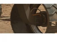
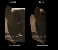
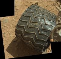
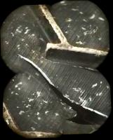
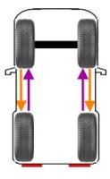
Ed: zooming in on that marvellous underbelly MAHLI montage, there appears to be further (and previously noted) deformation of the wheel surfaces.
Damage is most evident in the view of the front-left wheel inner surface.
Such wear has previously been discussed and concerns allayed.
Nevertheless, the front left wheel surface *appears* to have been punctured.
|
We've only done 700 meters, and have 7000 more to get to Mt Sharp.....
Given that more odometry has now accumulated, is any (re-)new(ed) concern valid?
DeanM
Posted by: jamescanvin May 16 2013, 10:15 AM
No, I wouldn't be concerned.
Yes there is a bit of damage, yes there will be 10x as much when we get to Mt Sharp, but the wheels will still be fine to drive on, this was expected.
Posted by: MahFL May 16 2013, 11:12 AM
Your going to have to regularly reassure us.....it looks bad to the layman. Of course at least the wheels can be regularly photographed as MSL roves accross this amazing landscape  .
.
Posted by: djellison May 16 2013, 02:05 PM

If the rover is still roving, such reassurance is utterly redundant.
Posted by: jmknapp May 16 2013, 02:56 PM
Isn't the "puncture" merely a glint of light? Could there be anything on Mars hard enough to make a narrow puncture through that much metal?
Posted by: mcaplinger May 16 2013, 03:03 PM
That's a nice empirical observation.
Somewhere in a review package I expect there's a detailed analysis of how the wheel was designed, with allowable levels of damage, predicted damage and margins. I haven't seen that package and if I had, I couldn't post the details anyway. So any assurance I could offer on this forum wouldn't really be fact-based, but I assume the designers had it under control.
Over on nasaspaceflight.com someone proposed a drinking game based on how many times this comes up
Posted by: mcaplinger May 16 2013, 03:06 PM
I won't speculate on these images, but the wheels are pretty thin (I don't know what the actual number is) and the loads can be pretty high on a sharp rock.
Aluminum isn't that hard.
Posted by: fredk May 16 2013, 03:13 PM
About reasurrances, it would be interesting to hear from someone who knows something about the engineering of the wheels. Does the thin skin covering the circumference of the wheels, which is dented, actually provide significant structural strength to the wheels?
Or does the skin just prevent sand and dust from getting into the wheel mechanisms inside, and the raised, narrow, treads are actually providing the main structural strength? In this case the skin could be severely punctured and torn and we could still drive.
Edit: scooped by Joe, and thanks mcaplinger for the details.
Posted by: Ant103 May 16 2013, 03:59 PM
It can't be. We are seeing these things in shadow, and from where there are, impossible to have the sky in sight. Because of the wheel itself, and the rover body.
I'm wondering about the material used to build theses wheels. At first, I thought they where designed in the exact same way as the MER's : a metalic monobloc.
Posted by: fredk May 16 2013, 05:33 PM
Being in shadow means they couldn't reflect the Sun, but they still could see some part of the sky and reflect it. The sky is a big thing so it's hard to block all of it!
Posted by: PaulH51 May 16 2013, 07:56 PM
I am sure this wheel debate will roll on for some time (pun not really intended). I have not found the specification for the material for the rover wheels, but judging from the number of dings in the rims we know the material is very ductile, but it appears to be a high performance aluminium alloy. Reassuringly aluminium remains ductile even at extremely low temperatures, but good to see that drives have occurred at mid day when the temperature ranges reduce any fatigue issues created by very low temperatures.
I would not be concerned with small punctures in the rims, after all we already have the 'Morse Code' cut outs, nor would I be concerned with a plethora of additional dings that we can expect during the remainder of its mission, but am concerned about possible 'work hardening' of the material which over time could reduce the ductility of the material that could lead to undesirably issues.
I am sure the engineering team and drive planners will remind the science team from time to time that the rover wheels are not designed as rock crushers and that we would like them to last as long as the power supply
Posted by: mcaplinger May 16 2013, 08:02 PM
See slide 32 in http://trs-new.jpl.nasa.gov/dspace/bitstream/2014/42424/1/12-0690.pdf
Posted by: djellison May 17 2013, 09:36 PM
It is. That 'hole' is a dent, the stress of the dent has popped the anodized coating off the inside of the wheel and we have bare aluminum reflecting the sun. That dent isn't in shadow. Those that are can reflect the bright martian sky off them. Just because something is in shadow - it doesn't mean it can't 'see the sky'.
Look at it - it's not even the same color as the terrain behind it.
And even if it IS punctured - it doesn't matter.
Once of the test-bed rovers at JPL had flight like wheels whilst dealing with 3x the effective weight of a real rover. The wheels were punctured, dent ridden, ripped, torn, dinged, bashed, smashed, crunched. You could put your finger thru the holes in places - you could see clean thru them.
And they still worked absolutely fine.
That testbed now has tougher wheels simply to deal with terrestrial gravity. The lightweight scarecrow rover has flightlike wheels.
I'm not sure how long it's going to take until saying 'the wheels are fine' before it gets boring. Infact, I think it might already have passed.
Posted by: djellison May 17 2013, 10:01 PM
That's exactly what I've heard from the team - and what it looks like having held a few spare wheels.
Posted by: Ant103 May 17 2013, 10:01 PM
Okay Doug, thanks for this very clear explanation
Posted by: fredk May 18 2013, 03:10 PM
And they still worked absolutely fine.
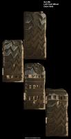
http://dougellison.smugmug.com/Machines/Mars-Yard-2012/23370887_zGB3Dr#!i=1887241240&k=s8zbL7R showing the VSTB rover with that damage. Worth a thousand words.
Posted by: djellison May 18 2013, 04:04 PM
Wonder who took those. 
And the wheels got a lot worse than that before they were replaced. A LOT worse.
Worst one at that point looks to be the middle right - rips and tears all over it
|
Posted by: jmknapp May 18 2013, 08:24 PM
Good thing Mars surface gravity is only 0.38g.
Posted by: testguru May 18 2013, 08:57 PM
Given the level of damage observed so far on the rover wheels and the small distance traveled, if you linearly extrapolate future damage vs distance traveled, how far can the rover drive before a wheel fails? I know no one can answer that but I would assume modeling is being done to try to answer that question??
I would also assume the rover drives will be planned to avoid sharp rocks whenever possible?
Posted by: Jimbo1955 May 18 2013, 09:27 PM
Look at it - it's not even the same color as the terrain behind it.
And even if it IS punctured - it doesn't matter.
Once of the test-bed rovers at JPL had flight like wheels whilst dealing with 3x the effective weight of a real rover. The wheels were punctured, dent ridden, ripped, torn, dinged, bashed, smashed, crunched. You could put your finger thru the holes in places - you could see clean thru them.
And they still worked absolutely fine.
That testbed now has tougher wheels simply to deal with terrestrial gravity. The lightweight scarecrow rover has flightlike wheels.
I'm not sure how long it's going to take until saying 'the wheels are fine' before it gets boring. Infact, I think it might already have passed.
I certainly don't know the coating or type of specific anodizing used, but anodizing in general is not a coating that can be "popped" off. Anodizing involves an etching process process to create a sponge-like texture into the metal. Dyes or other other additives are infused into the spongy porous surface of the metal. Could the anodized metal have a coating applied over it? Sure. I would rather suspect that a gouge in the metal which removed the anodized metal to expose the un-anodized surface.
-J
Posted by: Explorer1 May 18 2013, 09:32 PM
Good thing there's no shortage of soft surfaces on the way to Mt. Sharp. The dune fields are looking inviting, ironically (obviously we haven't seen them from the surface yet so pure speculation on what they're like).
Posted by: mcaplinger May 19 2013, 01:00 AM
Anodizing is an electrochemical process whereby the top layer of aluminum is converted to alumina (AlO2) -- http://en.wikipedia.org/wiki/Anodizing
There are several types and they tend to produce different thicknesses of alumina. In my experience, you can get a thin layer to pop off if you work at it, but I suspect that these dents are just specular highlights off the intact anodizing, since the black anodizing is not very matte.
Posted by: mcaplinger May 19 2013, 01:08 AM
I would also assume the rover drives will be planned to avoid sharp rocks whenever possible?
It's not really a linear process. The tire is one solid piece of aluminum. It would have to be ripped all the way across so it started unpeeling from the flexures before driving would be impeded. Like the viewgraphs I linked to earlier said, localized rupture in the tire was expected.
We're talking about sharp pebbles, I don't think driving around them would be feasible.
Posted by: mcaplinger May 19 2013, 01:10 AM
Doug has seen the damaged VSTB wheels in person and I haven't, so he's in a better position than me to know if the anodizing is actually broken off or not.
Posted by: djellison May 19 2013, 01:15 AM
Further than the rover will ever drive. Period.
Posted by: Bill Harris May 19 2013, 01:46 AM
The likely failure point will not be on the wheel tread surface itself, but at the annulus on the inner surface where the wheel spokes attach to the wheel.
--Bill
Posted by: mcaplinger May 19 2013, 02:18 AM
I'm not following your reasoning; the entire tire is one piece of aluminum, beefed up where the flexures attach.
Maybe the slide I referenced will be useful.

|
Posted by: serpens May 19 2013, 04:42 AM
Cool design. Wheels are NOT a likely failure mode. How many ways need this be said before the subject is dropped?
Posted by: djellison May 19 2013, 05:31 AM
Seemingly we're not done yet. Insert heavy to industrial strength 'sigh' here.
Posted by: stevesliva May 20 2013, 02:12 AM
Is that the sound of dust being wiped off Opportunity's solar panels?
Posted by: elakdawalla May 20 2013, 03:57 AM
OK, that was pretty funny.
Posted by: djellison May 20 2013, 04:03 AM
Yup - hats off to that one
Posted by: MahFL May 20 2013, 11:54 AM
Maybe the slide I referenced will be useful.
Actually you referenced slide 32, and it's slide 31, that threw me a bit, lol.
Posted by: Keatah Oct 7 2013, 02:33 AM
The MER and MSL builders got a lot of things right when they put them together. I'll assume they know what they're doing with the wheels.
Correct me if I'm wrong:
I understand the punctured aluminum is little more than soda can thickness and provides little or no structure strength.
I understand the cleats are considerably thicker and beefier and it is these that provide shape and strength.
I understand that the wheel motors are insanely high torque and could rotate the wheels if they were triangular shape.
I also assume that the wheels (initially with full undamaged surface area) would tend to float on dust and other lightly packed terrain. This I assume will change over time as the thin aluminum gets punched out and ripped up. Now you have less surface area, and the cleats will tend to sink more easily in sand. And at the same time, this digging-in would provide excellent traction. And perhaps even better traction when challenged against more rocky material.
Make no mistake, I was horrified to read about this! But if what I said is true, and I'm right, and the builders did their job, then there's nothing to worry over.
Posted by: pospa Oct 7 2013, 08:35 PM
One question related to this topic, ... I hope.
As far as we know MER wheels are made of Aluminium 7075-T7351.
Could anybody confirm MSL wheels are the same alloy?
Thx.
Posted by: Gerald Oct 10 2013, 07:35 AM
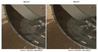
Sol 411 MAHLI x-eyed stereo showing part of a wheel:
|
Posted by: djellison Oct 10 2013, 01:32 PM
Remember - the wheels were built with several large holes in them....that spell JPL in morse code.
They make little to no difference to traction or surface pressure. Remember - it's 899kg across 6 wheels each with basically the same surface contact patch. It wont change significantly with a few dings and dents in it.
However - your conclusion "the builders did their job, then there's nothing to worry over" is 100% accurate.
Posted by: xflare Oct 16 2013, 10:48 AM
Another hole
http://www.midnightplanets.com/web/MSL/image/00424/NLB_435147127EDR_F0191066NCAM00354M_.html
Posted by: infocat13 Oct 18 2013, 11:16 PM
They make little to no difference to traction or surface pressure. Remember - it's 899kg across 6 wheels each with basically the same surface contact patch. It wont change significantly with a few dings and dents in it.
However - your conclusion "the builders did their job, then there's nothing to worry over" is 100% accurate.
I would love to see the machinery used to fabricate the wheels
Posted by: djellison Oct 19 2013, 01:42 AM
Go to any aerospace grade machine shop.
Posted by: pospa Oct 19 2013, 08:24 AM
Or visit directly Next Intent where they produced all MSL and MER wheels http://www.nextintent.com/portfolio-2.
Posted by: Gerald Nov 25 2013, 03:21 PM
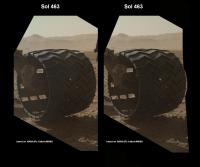
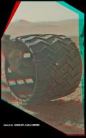
Sol 463 MAHLI x-eyed stereo of the left central wheel:
|
... and the left front wheel:
|
Posted by: elakdawalla Nov 25 2013, 04:29 PM
Wow. 
Posted by: walfy Nov 25 2013, 05:13 PM
The wheel for the glasses:
|
Posted by: Gerald Nov 28 2013, 12:53 PM
http://astrogeology.usgs.gov/news/astrogeology/sol-469471-update-on-curiosity-from-usgs-scientist-ken-herkenhoff-tearing-on-wheels
Posted by: MahFL Nov 28 2013, 04:56 PM
Well there you go, if the team were concerned about the wheels, then all of our concerns were validated.
Happy Thanksgiving by the way, to those that are celebrating it.
Posted by: mcaplinger Nov 28 2013, 05:10 PM
In my experience, science teams are no more immune to having concerns about things outside their area of expertise than any other group.
Posted by: djellison Nov 28 2013, 05:18 PM
Sharing a concern doesn't in any way validate it.
And just to repeat ( because seemingly it does bear repeating ) there is nothing to be concerned about. This is expected. It doesn't damage the rovers mobility.
Concerns about wheel damage are not..repeat NOT valid.
Posted by: bobik Nov 29 2013, 06:39 PM
Are there any papers on MSL wheel design trade-offs?
Posted by: mcaplinger Nov 29 2013, 06:59 PM
Did you read the viewgraph package referenced in http://www.unmannedspaceflight.com/index.php?showtopic=7658&view=findpost&p=200198 ?
Other than that, I don't know of anything. There are some useful quotes in http://news.discovery.com/space/rough-roving-curiositys-wheels-show-wear-and-tear-130522.htm (from May 2013)
Posted by: Phil Stooke Nov 29 2013, 07:37 PM
One way to look at this is that the cleats really do most of the work, and they are a lot more robust.
Phil
Posted by: serpens Nov 29 2013, 09:33 PM
So one can posit a scenario where rather than picking up a rock in the wheel as did Spirit, as the skin of the wheel deteriorates Curiosity could pick up a rock jammed between cleats. Wouldn't stop operation but would make for amusing comments.
Posted by: Explorer1 Nov 29 2013, 09:38 PM
Who says MSL has no sample cache... 
Posted by: bobik Nov 30 2013, 08:55 AM
It would be interesting to know what other wheel options and materials they considered. What role has the function as the landing gear pads played in the wheel design?
Posted by: pospa Nov 30 2013, 01:01 PM
I'm wondering what is the weight penalty by 2nd set of VSTB wheels with doubled skin thickness.
I guess that using 1,5 mm thick skin instead of 0,75 mm actually used on Mars would eliminate most of wear we see, stop all timorous comments around and would not hurt total rover mass budget significantly.
... maybe for Mars rover 2020.
Posted by: djellison Nov 30 2013, 08:13 PM
Well - the wheel rim itself would way about twice as much. I've held one. They're not 'heavy' but there's certainly a few KG's in there.
And you're forgetting - compliance in the wheel is one of the design requirements to take the edge of impacts as wheels drop off rocks etc. Making it 'stronger' just so it doesn't get holes in it ( holes that don't matter ) could very well be counter productive.
Why would you change the design for 2020. They work. They work great. There's nothing whatsoever to suggest they're going to stop working. Why would you invest a second of time, energy, or money - or mass budget - in making them unnecessarily heavier?
Posted by: pospa Nov 30 2013, 10:30 PM
If she's gonna work 14+ years and 2020 rover is equiped with the same wheels we'll go nuts from reading endless comments about 'weak torn wheels'.

PS: I talked about doubled 'skin' thickness only (0,75 -> 1,0~1,5 mm), not to strenghten all design elements as radial and axial ribs => for sure not doubled rim weight and less elastic 'wheel-bumper'
PS2: I fully trust engineers that they've made the best optimal design in compliance to all spec and that mobility won't be limited by wheels anytime during prime or future mission extensions.
Posted by: djellison Nov 30 2013, 11:47 PM
That could be solved by not posting endless comments about 'weak torn wheels'.
Not by pointlessly changing a vehicle design.
Posted by: mcaplinger Dec 1 2013, 12:13 AM
I'll confess that I've made minor engineering changes just to stop baseless concerns, so let's look at the details. If the wheels are 0.5m in diameter and 0.4m wide, then roughly speaking the outer surface volume is pi*0.5**2*0.4*0.75e-3 = 235 cm3 and its mass (aluminum density is about 2.7 gm/cm3) would be about 600 grams. Doubling the thickness would increase the mass to about 1.2 kg per wheel (times six of course) so the overall mass increase would be about 3.6 kg -- nearly twice the mass (for example) of two Mastcam camera heads. [edit: of course each wheel's mass is greater than 600 gm, this is just a rough cylindrical approximation of the mass of the 0.75mm "skin" of the wheel. For reference, 0.75mm is about 7x thicker than a typical Coke can.]
However, I don't see much evidence that anyone actually read the viewgraphs I linked to. It's worth remembering that unlike MER, MSL relies on the wheels to absorb not only driving loads but landing shock, and the wheels may have to elastically deform a fair bit in the process. Making the wheels thicker would reduce their ability to do so; I'm not sure by how much, but it could be a concern.
Posted by: djellison Dec 1 2013, 02:08 AM
Well - I did ;-)
Posted by: mcaplinger Dec 1 2013, 03:00 AM
Of course I wasn't counting you, Doug.
Posted by: Gerald Dec 4 2013, 01:04 PM
http://astrogeology.usgs.gov/news/astrogeology/sol-472473-update-on-curiosity-from-usgs-scientist-ken-herkenhoff-watching-the-wheels:
Besides monitoring, whether there ever could occur wheel damage justifying some concern:
Can wheel "damage" be quantified in a way, such that the wheels can be interpreted as an additional mechanical science instrument to retrieve some statistics about an appropriate physical/geological property of the traversed surface?
Posted by: paxdan Dec 4 2013, 02:04 PM
Yes it can and just such an experiement was done using the Sojourner Rover. It was called the http://www.grc.nasa.gov/WWW/RT/RT1997/5000/5410ferguson.htm (WAE). Thin films of different metals were emplaced on the http://commons.wikimedia.org/wiki/File:Mars_Pathfinder_Wheel_Abrasion_Experiment_.gif. A photovoltaic cell was used to periodically measure the reflectivity and record the level of abrasion thus characterizing the surface properties.
Posted by: Gerald Dec 4 2013, 02:35 PM
Thanks a lot! So there is a good chance, that we get additional science benefit from the wheel monitoring.
Posted by: dilo Dec 4 2013, 02:46 PM
A small question: could the recent wheel status worsening be related to the long, high average speed drive on http://www.unmannedspaceflight.com/index.php?s=&showtopic=7457&view=findpost&p=205060?
Posted by: Phil Stooke Dec 4 2013, 03:12 PM
No - 472 was the last drive, so we have not seen any MAHLI images since then. The 472 images are from before the drive.
Phil
Posted by: djellison Dec 4 2013, 03:41 PM
There's no such thing as a 'high speed drive'. When in motion the rover is typically at the same speed. 3cm/sec.
What you're perceiving as 'high speed' is a blind-drive ( no stops ) compared to autonav ( many freqent stops )
The speed of the rover when in motion is the same regardless. Go look at some speed plots at http://curiositylog.com/ to see the typical speed over time of the rover.
Posted by: mcaplinger Dec 4 2013, 04:41 PM
I would hesitate to call this science. At best we get a crude idea about rock size statistics, cruder I expect than what you could get just by counting rocks in images.
Posted by: dilo Dec 4 2013, 08:43 PM
Thanks Phil/Doug, I already linked Joe's speed plot in my previous post, however I had the (probably wrong) impression that constant "high" speed with no stops can cause more damages!
Posted by: centsworth_II Dec 4 2013, 08:58 PM
Posted by: dvandorn Dec 4 2013, 09:01 PM
I doubt there is a huge amount of straight scientific data about the surface to be gleaned from examining the wheels. However, there is good engineering data about the interaction of this particular wheel design with a fairly representative Martian surface to be acquired.
There has always been a dissonance between "pure" scientific data gathering during space flights, and the acquisition of engineering data that can be useful in the design phase of the next vehicle to come along. Both are "scientific" goals, but the engineering data is used to both improve future spacecraft and to better understand and improve our engineering models (which usually led to the designs and materials being used and evaluated).
Or, to put it another way, the "pure" scientific data is usually all about studying the environment we've come all this way to look at, while the engineering data is to look at the systems that got us there and keep us running so we can pursue the pure science goals.
-the other Doug
Posted by: serpens Dec 4 2013, 10:00 PM
Well said Doug, and both areas of analysis are of equal importance on a mission.
Posted by: djellison Dec 4 2013, 10:16 PM
Why you would come to that conclusion I don't know - but yes - it's wrong.
Posted by: Jimbo1955 Dec 7 2013, 06:00 PM
What surprises me about the wheel damage isn't the dents. That would be expected in thin aluminum. But the gaping holes are surprising to me. It's like the alloy is very brittle.
Posted by: mcaplinger Dec 7 2013, 06:45 PM
I assume (with no evidence to support it) that the wheels are 7075 alloy, which is somewhere near the upper end of aluminum alloys for fracture toughness -- http://en.wikipedia.org/wiki/Brittle_strength . http://en.wikipedia.org/wiki/Fracture is a useful intro to various types of fracture; see "ductile fracture". I'm not a mechanical engineer or a materials scientist and a hole is a little surprising to me too, but I'd rather see a clean hole than a big propagating rip.
To anticipate a question, aluminum is less subject than say, steel, to low-temperature embrittlement. See http://www.keytometals.com/page.aspx?ID=CheckArticle&site=ktn&NM=23 -- "Below zero, most aluminum alloys show little change in properties; yield and tensile strengths may increase; elongation may decrease slightly; impact strength remains approximately constant. Consequently, aluminum is useful material for many low-temperature applications."
To sum up (note that this is all my opinion derived from public information because I've intentionally not looked at any project-internal sources on this): yes, there are holes in the wheels. Some level of wheel damage was clearly anticipated by the designers. There are a lot of tradeoffs in the MSL wheel design and it may well have not been feasible to make wheels that were impervious to puncture. Imaging the wheels is being done, presumably to assess the amount and evolution of damage. Exactly what the level of concern is, if any, is something for the project to say.
Posted by: nprev Dec 7 2013, 07:28 PM
Given the fact that much larger holes were manufactured into the wheels for the JPL Morse tracks, my concern level is zero.
Posted by: djellison Dec 7 2013, 07:50 PM
Everything I've heard and read, repeatedly, states it's not a concern.
There were holes in the wheels on the VSTB rover in the Mars Yard long before MSL launched. This shouldn't really be a surprise to anyone.
Posted by: serpens Dec 7 2013, 09:42 PM
So why not put this thread to bed.
Posted by: djellison Dec 7 2013, 10:06 PM
Group therapy for the morbidly pessimistic.
Posted by: ngunn Dec 7 2013, 10:07 PM
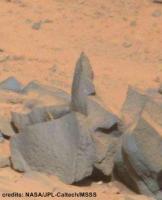
Pictures of the wheels are great, particularly when a wheel is perched on a rock. That tells us that a particular rock is mechanically strong, unlike some of the poorly consolidated sediments around. There should be a place for posts like that. But I agree: time should be called on endless unfounded worries about the wheels.
Posted by: Jimbo1955 Dec 7 2013, 10:33 PM
I was not talking about the large rectangular Morse Code holes, but the irregular large holes with jagged edges.
http://www.unmannedspaceflight.com/index.php?act=attach&type=post&id=31571
It's just surprising, that's all. I don't want to re-hash old stuff. Originally these were dismissed as glints or reflections. I just find it interesting that with 6 wide wheels with such a large contact area and reduced gravity, that one rock would be able to punch a hole in the material.
I won't comment anymore.
Posted by: Phil Stooke Dec 7 2013, 10:49 PM
We get that, but the other holes show that the ones you asked about don't matter. They can't spread far because of the big cleats. It's interesting to see this but it doesn't matter.
Now let's get back to looking at the stuff you can see through the holes: Mars.
Phil
Posted by: bobik Dec 8 2013, 05:48 PM
Why not use tires made of a titanium alloy?
Posted by: mcaplinger Dec 8 2013, 06:17 PM
Because they would weigh more and be less compliant; the wheels are basically the only shock absorbers in the system.
I have to say I feel a bit conflicted about this thread. On the one hand, some posts seem to be armchair engineering suggesting that there's something wrong with the system. On the other, some are just mostly-baseless cheerleading. I've tried to stay in between those two places by talking about the real engineering to the extent that I can, but maybe we've reached the point of diminishing returns on this topic.
Posted by: jasedm Dec 8 2013, 07:07 PM
I agree with the above sentiment, and with mcaplinger and others - surely this thread beat itself to death back in the summer?
If the wheels all completely fall to bits, and the rover takes an undignified nosedive into a pothole as a result, then people should feel fully justified in lambasting those who assured us that the wheels were up to the wear-and-tear.
Meantime.....
Posted by: nprev Dec 8 2013, 07:23 PM
I think that it's safe to say that the admin/mod team has decided to keep this thread open since over time more holes will appear, and hopefully it will function as a place for people to find answers (esp. those new to UMSF), which have been graciously provided by members such as mcaplinger.
However, alarmism will not be viewed favorably, nor will criticism of the project team or designers.
Engineering is all about compromise. We could have had massive wheels impervious in all respects to anything, but probably would have had to lose one or more instruments, and/or change something in the EDL methodology, and/or, and/or...it tends to snowball.
The wheel design is highly robust & survivable, and it's the best compromise that could be derived based on overall system performance requirements.
Enough said.
Posted by: bobik Dec 8 2013, 07:30 PM
I am only asking questions to learn about the engineering design process and considered wheel options unfortunately so far with little success. 
Posted by: nprev Dec 8 2013, 07:50 PM
Nobody's preventing you from doing so; again, that's what this thread is for.
My comments were not directed at anyone in particular; just wanted to define some boundaries.
Posted by: EdTruthan Dec 8 2013, 08:11 PM
These stereo views seemed to go better in this thread than anywhere else. The slight axial tilt of the camera during the MAHLI surveys allows for a reasonably robust stereo image of the center wheels on either side. Here are a few recent views (with brightness levels bumped in a few to bring out some detail in the shadows) ...
...from Sol 476:
http://www.edtruthan.com/mars/Sol476-Mahli-Wheels-1-Anaglyph.jpg
http://www.edtruthan.com/mars/Sol476-Mahli-Wheels-2-Anaglyph.jpg
...and from Sol 472:
http://www.edtruthan.com/mars/Sol472-Mahli-Wheels-1-Anaglyph.jpg
http://www.edtruthan.com/mars/Sol472-Mahli-Wheels-2-Anaglyph.jpg
(..and not to beat a dead topic, I personally think the wheels will be just fine even with a great number of holes - they have huge built in "JPL" holes - so it's hard to imagine enough damage to seriously impact the rover's mobility...)
Posted by: jasedm Dec 8 2013, 08:16 PM
A quick google search unearthed the following: 80+ pages of informed insight into the next generation (in which MSL is referenced) of rover wheels, and the engineering challenges/trade-offs faced by the terrain they would be exposed to. Admittedly the article references largely re-configurable wheels, but some of the challenges faced and the outcomes settled upon are instructive.
http://strategic.mit.edu/docs/SM-48-Baker-B-2012.pdf
Posted by: Gerald Dec 8 2013, 08:22 PM
I'd like to see more emphasis on the wheels as a science instrument. Streaks, scratches, dents, holes, tears can be seen as measurements.
Here just some simplified ideas:
Probably almost everyone working in mineralogy is best-familiar with determining http://en.wikipedia.org/wiki/Mohs_scale_of_mineral_hardness or using http://en.wikipedia.org/wiki/Streak_(mineralogy).
The frequency of scratches tells something about the abundancy of mineral grains harder than the aluminium alloy; streaks tell about cementation or about minerals softer than the alloy.
|
More advanced are http://en.wikipedia.org/wiki/Indentation_hardness, e.g. http://en.wikipedia.org/wiki/Brinell_hardness_test. From known force, Brinell hardness of the wheel, and observed indentation the diameter of the indentor can be determined.
The shape of indentations can e.g. be inferred from the shape of shadows.
|
From known penetration and fracture propagation thresholds, lower bounds of the loads causing penetration can be inferred.
From the driven distance the frequency per mars surface area can be calculated. So there are quantifyable data.
Monitored wheel data could e.g. be used to cross-check a simulation of the mission.
(Both images are regions of sol 476 MAHLI images, credit: NASA/JPL-Caltech/MSSS)
Posted by: stevesliva Dec 8 2013, 08:58 PM
Alloy? It's aluminum oxide from anodizing, right?
Posted by: Gerald Dec 8 2013, 09:28 PM
The very surface will be oxidized.
I've mainly been referring to the metal below the oxidized layer, which http://www.unmannedspaceflight.com/index.php?s=&showtopic=7658&view=findpost&p=205200 suspected to be http://en.wikipedia.org/wiki/7075_aluminium_alloy, consisting of aluminium, zinc, magnesium, and copper. Pure aluminium is rarely used.
Remains the question about the scratch resistance of the oxide layer.
Posted by: serpens Dec 9 2013, 02:08 AM
Well you are certainly thinking well outside the box there Gerald and full marks for that although I honestly cannot see any real utility in your suggestion. I guess that the hardness of the anodized layer will have been assessed although you would be pretty safe thinking it to be 7 < <9 (MOHS). Basalt has a MOHS of around 7 but the punctures in the wheel would be caused by small cross sectional contact where the effect on the basalt would be compression. There is no real time visual monitoring so no information available on when or where an incident (scratch, rear, puncture or crazing) occurred, or the dynamics. The anodized coating will have a different coefficient of thermal expansion than the underlying aluminium so there could be a degree of crazing caused by the Martian temperature variations which at the image resolution available would muddy the waters.
Posted by: djellison Dec 9 2013, 02:39 AM
However - we will never know what they are a measurement of. Which rock/soil/pebble etc cause what damage.
I'm afraid whilst your enthusiasm for this is admirable - there really isn't a legitimate means to extract quantitative data from this.
Posted by: Gerald Dec 9 2013, 11:00 AM
Let me just pick out one simple hypothetical(?) example, because elaborating everything is beyond my possibilities:
Imagine a green streak on a wheel.
My first association would be malachite, although unlikely on Mars. The wheels can look beneath the dust all along the drive, whereas the cameras can't.
If a dent is associated with the streak this may give an estimate of the shape of the peak which caused the streak, useful when driving back for detailed investigation.
http://en.wikipedia.org/wiki/Surface_roughness (to be applied to macroscopic features), which could be checked for their effect on the wheels, and possibly back-projected from wheel damage.
Just to inspire people to make more of it.
I'll (by default) return to monitoring/image processing.
Posted by: djellison Dec 9 2013, 04:05 PM
Let's say we have an 80m drive, at the end of which something like what you say is visible.
Where is it? Where on the 80m drive? There's no way of knowing. moreover you can only see perhaps 40% of each wheel, possibly less, from MAHLI at the end of any particular drive. So a situation may occur where we have one of your streaks visible on the wheel....and it might have actually occurred several drives previously - several hundred meters ago. How are you going to find it. Furthermore - anything a rear wheel runs over....has already been run over twice by the wheels in front.
Again - whilst your enthusiasm for this is admirable, I'm afraid it doesn't stand up to the realities of Mars, or rover ops.
There will in due time, I'm sure, be papers published about how the wheels are behaving - but attempting to characterize and identify particular rocks as part of the daily planning cycle....no....it's just not practical.
Posted by: fredk Dec 20 2013, 07:37 PM
http://mars.jpl.nasa.gov/msl/news/whatsnew/index.cfm?FuseAction=ShowNews&NewsID=1573
Posted by: jvandriel Dec 20 2013, 09:40 PM
One of the wheels on Sol 486.
Jan van Driel
|
Posted by: atomoid Dec 21 2013, 02:43 AM
little punched-out shred http://www.midnightplanets.com/web/MSL/image/00488/0488MH0262000000E1_DXXX.html and the http://www.midnightplanets.com/web/MSL/image/00488/0488MH0263000000E1_DXXX.htmlas well, seems to have been pushed in quite far. soon as it falls off were doomed!! 
the inside surface is rendering with some pretty convincing displacement mapping now.
Posted by: dtolman Dec 21 2013, 06:03 PM
Seems a bit of the wear worry is striking a chord with the team as well. While none of the dents and dings are serious, it apparently is more than they were expecting this far in. From the link above:
Posted by: elakdawalla Dec 21 2013, 10:40 PM
Yeah, and any pause to inspect the wheels is clearly at least briefly harmful to the goal of getting to Mt. Sharp as soon as possible, but hopefully in the grand scheme of things it is a miniscule one, so I'm not going to change my subtitle for this thread....yet.
I was thinking about how to harness the powers of this forum for good when it comes to the wheels. One question I often have when I see wheel photos is: are those new holes? Or are they old holes? If they are old, are they bigger than they used to be? I made myself a map of the wheels and was thinking about trying to note precisely where and when specific tears and holes were first noticed, hoping to use it to check subsequent wheel images to see if holes are new ones or old ones but it's a bigger job than I have time for. Maybe the attached PDF/PNG map of the wheels would be of some use to people...?
http://planetary.s3.amazonaws.com/assets/images/z-misc/2013/20131221_wheel-tread-map-01.png wheel_tread_map.pdf ( 1.53MB )
: 1060
wheel_tread_map.pdf ( 1.53MB )
: 1060
Posted by: Explorer1 Dec 22 2013, 12:04 AM
If they are concerned enough to be thinking about route changes, as Erickson is implying, what would that mean? Sticking closer to sandy, rock-free ground? The obvious place to go in that case is the dune field itself, but then there's concerns about getting stuck, and of course missing waypoint 4. Trade-offs, trade-offs, and more trade-offs...
Posted by: fredk Dec 22 2013, 02:14 AM
Here's an idea for an image wizard: transform the MH/mastcam/navcam images of the wheels into a strip map like what Emily's posted. Basically "unwrap" the images to a rectangular strip, or portion thereof.
I remember that someone did basically the same thing with images of a drill hole some time ago.
Posted by: Gerald Dec 22 2013, 02:29 AM
I think, it has been Zelenyikot, not quite sure.
In the short run, I just can provide as an example, that the idea works with the APXS inscription:

|
http://mars.jpl.nasa.gov/msl-raw-images/msss/00487/mcam/0487MR1913000000E1_DXXX.jpg.
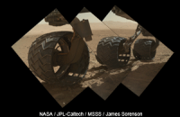
Posted by: James Sorenson Dec 22 2013, 06:28 AM
Here is an animated gif of the MAHLI images. It's not perfect, I tried to align everything to the wheels, so the horizon is going to flop up an down.
small
http://www.flickr.com/photos/43581439@N08/11490943014/sizes/o/in/photostream/
Large
http://www.flickr.com/photos/43581439@N08/11490853885/sizes/o/in/photostream/
Posted by: KingContrary Dec 22 2013, 11:28 AM
I was concerned when they went with the flashy (tall/ low-profile) aftermarket rims instead of the stock steel wheels. Yes, hubcaps look tacky on a 2.5 billion dollar super-rover, but in this case style over substance may cost us longevity.
Posted by: James Sorenson Dec 22 2013, 12:22 PM
Stock steel wheels? Aftermarket rims?
Steel wheels would have been far to heavy and costly. There is nothing wrong with the design of MSL's current wheels. Damage was expected and like it has been said over and over, will NOT impair mobility.
Posted by: mcaplinger Dec 22 2013, 04:34 PM
I think that was a joke.
While it would be interesting to use image processing techniques to generate the maps (define a model of the wheel, extract the image geometry from the SPICE kernels, have a camera model, map-project and mosaic, etc.) it would be simpler in the short term to do this by eye.
Posted by: centsworth_II Dec 22 2013, 04:45 PM
It will be interesting to see if there are any design changes to the twenty-twenty rover wheels based on these observations.
Posted by: Gerald Dec 22 2013, 09:46 PM
Four Sol 490 MAHLI images provide better coverage, here for one of the wheels:
http://makeagif.com/BrxS0e
Posted by: serpens Dec 22 2013, 10:42 PM
Almost sure to be some design changes. The space and weight trade-off considerations must cause some angst in mission design between the science and engineering design teams. The MER wheel and rocker bogey design was brilliant, with Opportunity still hobbling along having covered a distance of 65 times the mission success criteria, albeit primarily on soft sandstone. Curiosity's mass is 5 times that of a MER which required a modified design. But wheel design has to be based on a guestimate of what the ground environment will be like and while Curiosity is traversing sedimentary rock, she (is that gender correct?) has encountered a lot of sharp angular clasts which have done some cosmetic damage, although the structural integrity of the wheels is unaffected. Still, one thing we can be certain of is that the next rover will generate the same tired old blogging arguments on tracks versus wheels etc.
Posted by: Gerald Dec 23 2013, 01:25 AM
The gender is correct.
My humble try towards a "tread map" of the left front wheel, Sol 490, based on the same MAHLI images (0490MH026200000?E1_DXXX.jpg) used for the above animation:

|
Most of the distortions are due to my limited capabilities.
Posted by: James Sorenson Dec 23 2013, 04:13 AM
Cool!
All of the MAHLI images of right side of Curiosity from Sol 488-490. I'm working on the left side now.
|

|
Right side:
Small
http://www.flickr.com/photos/43581439@N08/11507724816/sizes/o/in/photostream/
Large
http://www.flickr.com/photos/43581439@N08/11507730746/sizes/o/in/photostream/
EDIT:
Here is the left side.
Small
http://www.flickr.com/photos/43581439@N08/11508840846/sizes/o/in/photostream/
Large
http://www.flickr.com/photos/43581439@N08/11508778165/sizes/o/in/photostream/
Posted by: Harder Dec 27 2013, 03:54 PM
Today I read in a French space magazine that NASA is thinking about changing the MSL route to Mt Sharp. The accumulated denting of the wheels is higher than originally anticipated, so a more benign route with lower wheel-damaging potential is being considered.
Posted by: brellis Dec 27 2013, 08:50 PM
Assuming there are energy expense issues related to driving (with dented wheels) vs. science objectives over the projected lifetime of the power source, do alternate smoother terrain routes already compromise some of the science? Is the base of Mt. Sharp such a prize target for examination that we need to "head for the highway"?
edit: I really want to see the view from the peak!
Posted by: Explorer1 Dec 27 2013, 09:05 PM
We all do; but the main science is the 'badlands' type terrain on the lower portions. The upper reaches are mostly windblown dust. I imagine the REMS team would like going to higher altitude to measure differences in temperature, pressure and winds compared with the base, but they're just one instrument. It's all about trade-offs...
Posted by: brellis Dec 27 2013, 09:47 PM
Does driving in general expend more energy than stationary science instruments? I assume so, but can't find that info on the Google Skimmer.
Posted by: atomoid Dec 27 2013, 10:18 PM
chem-cam examination of http://www.midnightplanets.com/web/MSL/image/00493/CR0_441262493EDR_F0240408CCAM10492M_.html? first i'm aware of.. a al http://www.unmannedspaceflight.com/index.php?s=&showtopic=7658&view=findpost&p=205241 prescient comment.
If there will be some plan to alter course to avoid wheel wear+tear, even though all this not too outside expected parameters and poses no problem at current rates, it raises the question exactly what goal re-routing for smooth sailing would be expected to accomplish? a smoother path probably means it will be covered more with sand and dust and fewer scientifically interesting outcrops to investigate. on the other hand, fewer science-stops could translate to arriving at the entry point or badlands sooner, if that's the point, but perhaps less to tell of the journey there...
one wonders what sort of performance the rover will have in soft sands, years from now after most of the soda-can films between the lattices have finally worn and flaked off. I suspect skeletonized wheels could actually be beneficial in a 'purgatory' situation..?
Posted by: TheAnt Dec 27 2013, 10:35 PM
I don't think there's no energy issues whatsoever for the situation right now, but if a sharp stone get jammed in one of the cracks the situation might be quite different, though the electric motors are rather of a slow speed but got a lot of torque.
There might also be some concern about the risk that a bit of metal come loose and manage to get jammed in the driving axle or that inside rim of the wheel. (The parts can be clearly seen in Geralds animation 8 posts up.)
Most of this concern might be for the state of the wheels in the later part (and for one extended) mission - the talk about choosing another path up the mountain concerns me. The suggested path were to maximize science results, and the ravine near the foot of the hills is the part of this mission that interested me the most, and I do have a hunch there's others who have been waiting for what might turn up there also. And not just for the view, but the mineral and geological history.
But changing the route to the mountain is ok with me, the sooner we get there the better.
Posted by: Explorer1 Dec 28 2013, 02:41 AM
Though they're correct in that this is not a dramatic 'mission killer' like many implied at the start.
It's more on the line of stuck heaters or right front wheels on the MERs.
Posted by: Gerald Dec 28 2013, 09:47 PM
The statement
(http://mars.jpl.nasa.gov/msl/news/whatsnew/index.cfm?FuseAction=ShowNews&NewsID=1573)
may include local choosing of a less damaging path to the same destination, either on a manual day-by-day basis, or by adjusting weighting for AutoNav or http://mars.jpl.nasa.gov/msl/mission/rover/eyesandother/:
It doesn't (yet?) look to me like a major change of the planned route to the entry point.
Posted by: serpens Dec 28 2013, 10:07 PM
Minor deviations from the planned track to 'swerve' around potentially damaging terrain seems like good applied common sense to me.
Posted by: TheAnt Dec 30 2013, 10:34 PM
Thank you Gerald, my interpretation of what was said were off then, it had me think of the largest scale.
So just as what Serpens said, then this is something that make sense.
Happy new year!
Posted by: elakdawalla Jan 4 2014, 06:19 AM
There are some really awesome http://www.midnightplanets.com/web/MSL/sol/00502.html, plus a http://www.midnightplanets.com/web/MSL/image/00502/NLB_442059532EDR_F0250000NCAM00526M_.html.
Posted by: Astro0 Jan 4 2014, 07:18 AM
Here's a mosaic of those chemcam images.
|
Stretched and sharpened (and that's just the images!)

Posted by: eoincampbell Jan 4 2014, 07:50 AM
...Great mosaic, surely a fix-it ticket 'till the buttes
Posted by: Mr Valiant Jan 4 2014, 02:03 PM
I know nothing (actally, td bits) about alloy wheels rolling over the surface of Mars, and I'm certainly not
having a dig. If it wasn't for this excellent Forum, I wouldn't know what a puncture or
tear in an alloy wheel of MSL was or looked like.
Surely, the fact that the MSL team will be plotting 'smoother' terrain in future is a hats off
to the folk who first expressed their concerns in May last year.
Sure the wheels should be robust enough through the design of the spokes and cleats to remain
circular, but holes, cracks, tears and buckles in the tread may become deleterious in soft, dusty situations.
Posted by: Zelenyikot Jan 4 2014, 03:56 PM
The wheelhole in colored ChemCam
|
Posted by: Gerald Jan 4 2014, 04:59 PM
To me the holes and tears tell the story, that several of the rocks are as sharp as knifes, some with almost the hooklike properties of a http://en.wikipedia.org/wiki/Can_opener.
That's certainly important to know for future missions, in cases where exposed vessels may need to be kept under pressure.
Edit (Jan 5 2014): A Sol 502 illustration:
|
(http://mars.jpl.nasa.gov/msl-raw-images/msss/00502/mcam/0502MR1976000000E1_DXXX.jpg)
Posted by: djellison Jan 4 2014, 09:24 PM
There are no grounds to make such an assumption. The wheels were built with many big holes in them, intentionally. The test rovers ( both VSTB and the Scarecrow ) have happily driven across soft and sandy situations with damage as bad, and significantly worse and more thoroughly distributed around all 6 wheels than we're seeing on Curiosity. Indeed - I've seen people argue that paddle like additions to rover wheels would be of benefit when trying to drive thru soft terrain, based on the notion of sand-paddle wheels for extreme off roading. Big rips and tears may even offer benefits along those lines.
I still see no damage ( nor any action by the team ) that presents any risk, whatsoever, to achieving mission goals. Nothing seen, announced or planned in any way could be considered a 'hat tip' to the doom-mongers in this place ( and elsewhere ) who were claiming mobility would soon be a thing of the past and we'd never get to the science targets at the foot of Mount Sharp.
People have been very carefully picking quotes from the JPL release....here's one worth remembering..
"The wheels can sustain significant damage without impairing the rover's ability to drive."
Posted by: serpens Jan 4 2014, 10:08 PM
to the folk who first expressed their concerns in May last year.....
Not really Mr V. People saw dings and a few punctures in the thin aluminium and many went well over the top in making ill considered comments. Such damage was not a surprise and was in fact expected from design trials with the test prototypes which as I understand it performed satisfactorily in dusty / sandy conditions with worse damage. The design teams for the MER and MSL have so many runs on the board that armchair observers could perhaps give them credit for a job well done rather than insinuating some kind of planning failure on their part. The decision to avoid potentially damaging terrain when there is no compelling science related requirement to transverse it is most sensible and does not imply any inability of the MSL to handle such terrain if required.
Astro0 - brilliant mosaic.
Posted by: nprev Jan 4 2014, 10:34 PM
Precisely, serpens, and well said!
Also, a nod to Gerald: Yes, any knowledge gained from not only the science but also the engineering performance of not just the wheels but ALL MSL mission systems under real-world conditions (that world being Mars in this case) will undoubtedly be used to refine future designs in all respects.
That's why it's called exploration, folks. We're right in the face of the unknown, in every way, and during every sol. It's not for the faint of heart.
Posted by: Astro0 Jan 6 2014, 09:20 AM
ADMIN: Previous four posts removed. Please read the Forum News>Important Announcements>http://www.unmannedspaceflight.com/index.php?showtopic=7773.
Posted by: Astro0 Jan 7 2014, 07:34 AM
http://planetary.s3.amazonaws.com/assets/images/z-misc/2013/20131221_wheel-tread-map-01.png
wheel_tread_map.pdf ( 1.53MB )
: 1060This would be a great project for someone here to undertake. Just what this particular discussion needs.
It'd be just as useful as the wonderful route maps that Tesh and Phil create.
If we get this 'rolling', then we'll set it up as a pinned thread.
|
Here's a good starting reference from Gerald to put onto the graphic that Emily created.
Any takers?
Posted by: dr_rick Jan 7 2014, 11:28 AM
thank you for this discussion and for the images posted, and in particular that posted by Astro0 9 posts back.
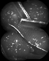
When I was looking at this, I was concerned that, at the end of what appears to be a crack or break in the wheel surface material (unless I have completely misunderstood the image - in which case, please forgive me - this is my first post here), there looked to be a distortion of the wheel surface continuing in the direction of the break, suggesting that a crack continues in that direction. I downloaded the image and fiddled with the contrast (attached) and believe that my initial observation is correct. In terms of monitoring the progress of the damage to the wheel, it will be interesting to see whether the cracking continues in that direction.
modified to make image clearer

|
Posted by: fredk Jan 8 2014, 04:11 PM
These two MH wheel views happen to show almost identical faces of the LF wheel - load them up in different windows and flip between them to see the changes between sols 488 and 506 (three shortish drives between them):
http://mars.jpl.nasa.gov/msl-raw-images/msss/00488/mhli/0488MH0262000001E1_DXXX.jpg
http://mars.jpl.nasa.gov/msl-raw-images/msss/00506/mhli/0506MH0262000000E1_DXXX.jpg
Apart from some new small scratches, there seems to be a new hole near the bottom of the wheel.
(Mods - sorry, I meant to post this in the wheel thread.)
Mod: Done.
Posted by: Phil Stooke Jan 8 2014, 04:18 PM
To me it looks like the hole was there before, but with shaded ground behind it instead of illuminated ground.
Phil
Posted by: dilo Jan 8 2014, 05:42 PM
Phil, I think fredk is referring to the red-arrow highlighted feature:

|
The opaque appareance and the straight borders suggests it is a simple light-spot projected from squared opening (windows) on top of the wheel (you can see another spot above it...).
Posted by: fredk Jan 8 2014, 06:16 PM
You may be right, Dilo - at first I thought that couldn't be sunlight shining through a hole because the inner wheel surface is quite dark grey, as you can see from the other light spot. But if there are patches of soil sitting on the bottom of the wheel, they would look bright orange when sunlit of course. Once we get a rotated view of the wheel we'll know for sure.
Posted by: elakdawalla Jan 8 2014, 06:50 PM
Yeah, I stared at that for a while this morning and couldn't decide either whether it was a new hole or a sunlight patch. I was leaning toward sunlight patch but don't see strong enough evidence to overturn anybody's call either way.
Posted by: Greenish Jan 15 2014, 04:00 PM
Looks like the ~1-meter drive on sol 513 was equal to a half-turn of the wheels, with MAHLI imaging of all wheels at 4 positions - I suppose the repeatability test for arm position the other day was with this in mind, though I don't know if we could tell other than from SPICE files if the arm was stowed for each step, or if they found a spot smooth enough to leave it deployed for these small steps. Wonder if they will do the other half-turn next sol, or if those positions are covered by other recent imaging? They downlinked and posted the images quickly, too - about 6 hours after taking them.
The good news is that there's not much discernable difference between sol 490 (right image) and sol 513 (left) on the worst spot on the front left wheel.

|
Posted by: Greenish Jan 15 2014, 04:25 PM
Should have read the news first. From Ken Herkenhoff (full text http://astrogeology.usgs.gov/news/astrogeology/sol-513-update-on-curiosity-from-usgs-scientist-ken-herkenhoff-early-planning):
Posted by: Olivier Jan 15 2014, 04:31 PM
Are all the wheels "in sync" ??? i.e. do they all show the same exact number of rotation on a given drive?
Olivier
Posted by: charborob Jan 15 2014, 04:53 PM
They would if you were driving in a perfectly straight line on a smooth surface. But on a rugged surface, and with turns, you obviously have different numbers of rotations. For example, during a turn, the outer wheels make more rotations than the inner wheels.
Posted by: fredk Jan 15 2014, 05:37 PM
Plus there will always be some wheel slippage, which will be different for each wheel.
Posted by: nprev Jan 15 2014, 05:47 PM
I believe that each wheel is independently controlled as well if they emulated the MER design philosophy. Therefore any rotational synchronization in term of identical RPMs (often over several Ms, frankly) would indeed have to be straight-line and frankly coincidental given external factors like slippage.
Posted by: elakdawalla Jan 15 2014, 06:05 PM
With all this recent wheel imaging, it really seems like it should be possible to produce a systematic survey of the current condition of the entire circumference of all the wheels. Just throwing that out there in case someone has the time to organize images into such a survey....
Posted by: Gerald Jan 16 2014, 12:35 AM
I've ideas for a 0th and 1st approximation of an "undistortion" algorithm for the wheel images. For the 0th approximation three points should be sufficent to retrieve the mantle of an assumed cylindric wheel. A fourth point as parameter may already be sufficient to take account of the perpendicular curvature.
This shouldn't be too difficult to program. May be I'll dare a try on Sunday.
Posted by: Astro0 Jan 16 2014, 07:28 AM
Yes please Gerald.....'Dare Mighty Things'!
Posted by: elakdawalla Jan 17 2014, 01:55 AM
I'm trying to get a handle on wheel geography in order to interpret the survey images and look for changes. These are all from the sol 513 MAHLI imaging. I count 20 inter-tread areas (where the punctures are forming) between treads. Because the Morse code makes such a good landmark, I am counting upward and downward from those spots to name the inter-tread areas, 10 up and 10 down. I'm noting locations of tears and punctures as they are closer to the rover (medial) or farther from the rover (lateral) or in between (central). So far I've just looked at the right-side wheels. Here's what I've found in this one set, keeping in mind that the RF wheel was incompletely surveyed. There were some spots I wasn't sure about. Now I need to complete the survey on the left side, and then compare back in time to try to note any others that I missed on this survey, and to try to put some constraints on when the tears initialized and worsened.
RF
6 down - big puncture, center
|
|
RM
5 down - small tear, center
9 down - big puncture, medial
10 down - small tear, medial
6 up - small tear, center
|
|
RR - nothing major
|
|
Posted by: Phil Stooke Jan 17 2014, 03:19 AM
Right-hand image, second one down: Number 8 has a T-shaped mark just to the left of the number.
Next image down: that same T-shaped mark is on the space numbered 9.
I don't see any other numbering errors.
Phil
Posted by: elakdawalla Jan 17 2014, 04:00 AM
Thanks, I fixed that.
Here's the rest. I wonder why the left middle and left front wheels have suffered so much more than the others, and why the two rear wheels appear to have escaped injury so far.
LR
Nothing major

|
LM
10 down -- big puncture, central
10 up - puncture, central
9 up -- 3 punctures, central
8 up -- "seagull" shape tear, central
6 up -- puncture, central
4 up -- very small tear, medial
|
|
LF
1 down -- huge rip, central, & tear, medial
2 down - small tear, central
4 down - small puncture, lateral
5 down - small tear, central
6 down - small puncture, central
10 down -- 2 small punctures, central
10 up -- small tear, central
5 up - small tear, central
4 up -- tear, lateral
2 up -- big puncture, central
|
Posted by: dvandorn Jan 17 2014, 05:29 AM
As has been pointed out, the MSL mobility testbed unit displays similar rips and tears in the wheels. It might be instructive to see the current status of the testbed wheels, along with a rough history of the number of meters it was driven and over what surfaces. I recall seeing video of the testbed recorded well before Curiosity landed that shows significant ripping and tearing in its wheels, so it must not take a huge amount of driving for these things to appear.
For the testbed experience to be truly applicable to the asset on Mars, I imagine the weight of the testbed would have to be roughly one-third of the actual MSL. I recall that the MER mobility testbed was weighted in this manner, I'm assuming MSL's was, too.
-the other Doug
Posted by: elakdawalla Jan 17 2014, 05:35 AM
The soil in the testbed area doesn't bear a lot of similarity to the exposed, angular rock of the Gale landing site.
Posted by: dvandorn Jan 17 2014, 05:48 AM
Okay. Well, hey, it was a thought. Might still be interesting to compare the testbed wheels to Curiosity's, if just see if the wear and tear on this wheel design is inherent in the design and will occur pretty much irrespective of the surface conditions, or whether a surface with a larger admixture of sharp-edged stones will (as common sense would suggest) cause more rips and tears.
Again, I have no doubt that the wheels will work fine even if large sections of the thin aluminum end up getting ripped and torn. As with many of us, I'm sure, I just find this an interesting engineering exercise. (The absolute worst image I have is of Curiosity sort of humping up and down if a large piece of metal ends up sticking out of one of the wheels, a dynamic I find unlikely considering that even if a piece were to catch on a rock and rip radially outwards, the wheel motion would then tend to push it harmlessly back in towards the wheel hub.)
-the other Doug
Posted by: vikingmars Jan 17 2014, 09:20 AM
Thanks a lot Emily for those much informative pictures !
Now we can see, thanks to your good processings, that the LR and RR wheels have much less rips, tears and punctures than the LF and RF wheels, it means that the front wheels are taking all the bad shocks, maybe crushing some pebbles and flattening the ground, somewhat "paving the way" for the rear wheels.
Thus, if the situation really worsens for the front wheels, a good solution would be to turn the rover 180° and drive backwards. Then, the "new" front wheels (the former LR and RR wheels) will "pave the way" for us... much like reversing the tyres on your car
|
Posted by: fredk Jan 17 2014, 03:20 PM
Yeah, I could believe that the rear wheels are somewhat protected, in that some sharp protruding rocks are pushed or rotated down by the front and middle wheels. Conceivably there could also be some difference due to the asymmetric rocker/bogey design.
Posted by: mcaplinger Jan 17 2014, 03:32 PM
Depends on what you mean by testbed. The VSTB (which Doug has posted pictures of) is a flight-like rover and probably has a mass similar to that of the flight system (I don't know if it has ballast for the RTG or not.) The "scarecrow" is 1/3rd mass but I don't know what the state of its wheels are/were.
Of course some of the dynamics depend on mass, not weight, so there's no way to perfectly mimic the behavior on Mars on Earth.
Posted by: James Sorenson Jan 17 2014, 11:09 PM
I'm kind of thinking since the Arm interfaces on the left side, once the arm is deployed, mass is shifting and putting more pressure on that wheel. If any sharp rocks are under the wheel, I wonder if that will cause a puncture because of that shifting mass as the arm is moving. Or another idea is while driving, since the heavy turret and shoulder joint of the arm are both on that side in a stowed config, perhaps that puts more weight on that wheel?
Posted by: djellison Jan 17 2014, 11:39 PM
It's big heavy arm and a lot of torque there if it's stuck out....but....if the rover moved enough for a wheel to get punctures during that process... we would see it in imagery of pre/post arm deployment. We've seen some motion...but only a tiny bit.
Posted by: mcaplinger Jan 20 2014, 05:25 PM
I think this is an interesting speculation, but given that the whole vehicle was hung from the descent stage with the arm stowed like this, I'd suspect it was fairly well-balanced and not much heavier on one side than the other. But I don't know for sure.
BTW, I put together the LEGO model of the rover yesterday. I can't say enough good things about it as a visualization tool for both the suspension and the arm. Highly recommended! http://shop.lego.com/en-US/NASA-Mars-Science-Laboratory-Curiosity-Rover-21104
Posted by: mcaplinger Jan 20 2014, 05:34 PM
Not doubting Doug at all, but just to put some numbers on that: according to http://www.esmats.eu/esmatspapers/pastpapers/pdfs/2011/billing.pdf the arm mass without the turret is 67 kg, and the turret weighs 34 kg. So it is quite heavy, and I could imagine that it does load up some of the wheels pretty significantly in some poses.
I'm not certain if the high-time-res rover orientation data makes it into the SPICE kernels, but if it does, it might be interesting to visualize how much movement the rover actually undergoes when it's nominally stationary.
Posted by: TheAnt Jan 20 2014, 11:30 PM
That's the weight on Earth right? On Mars that give me a weight of 37,47 kg. While the weight is lower, the mass being the same so agreed, it is quite massive also compared to the ones mounted on the predecessor rovers.
Posted by: mcaplinger Jan 20 2014, 11:38 PM
A kilogram is a measure of mass, not weight (I misspoke in my post; the turret mass is 34 kg). The arm has the same mass on Mars that it does on Earth. You say this yourself but I'm not certain what your point is.
That said, the resulting pressure on the wheel surface would be lower on Mars.
Of course, something is making holes in the wheels; it's either pressure (depends on weight); impact forces (depends more on mass); or some dynamic combination.
Posted by: elakdawalla Jan 20 2014, 11:51 PM
After thinking about it for a while, I've changed my numbering system because I decided the up/down nomenclature would get confusing. Here's the summary again of the status on sol 513, with a map of the places I spotted holes. The map should be regarded as "notional" -- it's very sketchy.
http://planetary.s3.amazonaws.com/assets/images/4-mars/2014/20140120_wheel_survey_sol513_all.jpg

|
I started looking at all the wheel imaging campaigns that have been performed since sol 463. There are tons. Here is 463:
http://planetary.s3.amazonaws.com/assets/images/4-mars/2014/20140120_wheel_survey_sol463.jpg
There has been change in that time. I don't know if the map is the way to go for looking at change. A different way of going about looking for change is to construct a spreadsheet, where I note which inter-cleat spaces were seen on which sols, and note whether they contain holes. This approach has helped me find change. For one example, there is a biggish hole at the medial side of spot 9 on the right middle wheel that first appeared between http://www.midnightplanets.com/web/MSL/image/00463/0463MH0260000000E1_DXXX.html and http://www.midnightplanets.com/web/MSL/image/00469/0469MH0261000000E1_DXXX.html. That new hole is on the edge of visibility in sol 469; it's easier to see in http://www.midnightplanets.com/web/MSL/image/00476/0476MH0261000000E1_DXXX.html. Incidentally, this is the same one that they targeted for RMI imaging on http://www.midnightplanets.com/web/MSL/sol/00502.html. The right middle wheel is easy to track because it's the easiest one to see from the mast-mounted cameras. In a sense, it's fortunate that the rear wheels appear to be less damaged, because they're the hardest ones to see.
Posted by: Gerald Jan 21 2014, 01:05 AM
I'm persuing your approach of the pdf template.
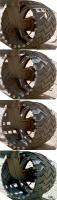
Here a 720 degrees version of http://mars.jpl.nasa.gov/msl-raw-images/msss/00513/mhli/0513MH0264000001E1_DXXX.jpg:
http://imgur.com/jgK24ql
Not yet quite perfect. But composing/stitching four appropriate fragments of this kind of images could return a geometrically almost normalized view of a wheel mantle, hence allowing a better comparison of changes, or even providing the basis for a texture applicable to a 3d-model.
Posted by: elakdawalla Jan 21 2014, 01:11 AM
Pretty cool! That twist in the middle was quite a puzzle, until I realized you're projecting the inside surface of the wheel in the part of the view where that's what's visible, and the outside surface where we see that, and the brain-bending twist is where the viewer's sightline is tangential to the wheel's surface. Nice. It looks really excellent in the positions where it's at a moderately high angle to the camera.
Posted by: Gerald Jan 21 2014, 09:02 AM
Thanks for explaining the image! I could't have done it better, at least late in the night after a long day.
The underlying idea of the projection is, to wrap a rectangle around a cylinder, bend and translate this cylinder a bit, until it matches with a wheel in 3d relative to the camera, then simulate the mapping of the wheel by the camera. To put the color of a pixel within the rectangle, get the color of the raw image at the described transformed position.
My simulation of the wheel and the mapping by the camera needs some more refinement to get a well-standardized geometry.
I'll work on this in small steps, and let you know, when it's more or less satisfying to my eyes.
Posted by: TheAnt Jan 21 2014, 02:16 PM
I am sorry, before posting I edited my reply into obscurity.
I mail that part over to you.
@elakdawalla: Thank you and I prefer the new number system.
Posted by: Cruzeiro do Sul Jan 31 2014, 11:11 PM
Emily, this "map" of the weels is so good! Can I use it in a space exploration french forum to illustrate theses weels anomalies? Citing that this is your work, obsviously!
Posted by: Gerald Feb 2 2014, 08:26 PM
Next step of Sol 513 MAHLI left center wheel image processing:
By wrapping the wheel into a cylinder-like surface (radius varying according to an appropriate parabola), and projecting it into the raw MAHLI images
http://imgur.com/CXSuZiX
the surface of the wheels gets geometrically standardized to a near-rectangle
http://imgur.com/5hSfJ0z
Cropping and stitiching results in a transformation to a standardized geometry (similar, but not quite identical to the cylindrical map projection):
http://imgur.com/yaVNWNa
Posted by: fredk Feb 2 2014, 08:39 PM
Seriously cool - and exactly what I envisioned a wizard could do!
Now the next step is obvious - repeat for later sols and animate to see the changes. Hopefully you can turn at least most of the steps into an automatic pipeline so it's not a tremendous amount of work for each set of images...
Posted by: Gerald Feb 2 2014, 09:12 PM
Thanks!
The manually difficult unwrapping is mostly automized, reduced to a couple of parameters which I need to adjust between images. So I'm optimistic, that the steps you're suggesting become feasible.
Posted by: SteveM Feb 2 2014, 09:28 PM
Thanks, very nicely done. Hhope adapting the process to the remaining five wheels won't be too much further effort.
Posted by: Gerald Feb 2 2014, 09:59 PM
I didn't yet test the other five wheels. It's probably one or two further parameters to be adjusted, mainly the distance to match size and perspective.
I'm dreaming of a fully automated feature recognition subroutine to eliminate any manual adjustment, but that's certainly more than a few hours of work at a week-end.
Posted by: mcaplinger Feb 2 2014, 10:26 PM
https://xkcd.com/1319/
Posted by: Gerald Feb 2 2014, 10:36 PM
i c u r doing this job since quite while.
Posted by: testguru Feb 8 2014, 07:15 PM
I have a few questions about the wheel design on the current rover and the next rover:
1. Was there a design spec on having to navigate dunes? Is so what was it?
2. Has any thought been given to modifying the next rovers wheel design to make traversing a dune "easy"
3. Has any thought been given to use of "tank tracks" instead of individual wheels?
Posted by: Zeke4ther Feb 8 2014, 08:30 PM
Actually point 3 has been already discussed on the MER forum.
The problem with "tank tread" designs are the mass penalty and, more importantly, treads can get thrown or break.
When that happens then your rover becomes crippled. With the current design, even if one wheel fails you can still move.
Spirit was able to do this for years 
Posted by: Gerald Feb 8 2014, 08:37 PM
http://www.youtube.com/watch?v=sjhM9uJfqB4.
Posted by: testguru Feb 9 2014, 01:17 AM
Thanks for that link.
The video indicates that the rover can do about a 20 degree slope in soft sand if I am understanding properly. Was there a hard spec on the maximum angle that the rover could traverse in soft sand?
I watch this site every day and get a feel for the anxiety that everyone has felt about trying to drive over a ~ 3ft dune. Now that Curiosity has done that I assume the anxiety will lessen for the same size dune in the future?
Since it is pretty much impossible to perfectly simulate Mars on Earth I guess we will never know for sure what the limits are on dunes until we measure the result for the first time with the rover on Mars.
I also understand the reluctance to find those limits.
Pretty much anywhere we go on Mars is going to have sharp rocks and dunes.
On the next rover mission we should be able to place a larger payload on Mars using the same rocket due to the more favorable launch window, (pretty much the best perihelic opposition for the next 13 - 15 years).
I hope that the wheels can be beefed up or replaced with something better. Folks have been saying that the next mission will not be a carbon copy of this one or even close.
Posted by: Explorer1 Feb 9 2014, 01:41 AM
Depends on the landing site surface, which is far from decided. It could be like Meridiani for all we know.
Posted by: PaulH51 Feb 9 2014, 02:08 AM
Another nice set of MAHLI wheel images has been down-linked from sol 0537. One advantage with this set is the light dusting of sand on the inside of the wheels, that has helped to differentiate between small punctures and reflected light off the dimples which has sometimes been interpreted as punctures.
Posted by: RoverDriver Feb 9 2014, 07:35 AM
Now that Curiosity has done that I assume the anxiety will lessen for the same size dune in the future?
...
One would think but Mars has proven to be a nasty place with surprises every now and then. We have learned some hard lessons so we never let our guard down.
Paolo
Posted by: Explorer1 Feb 14 2014, 11:34 PM
A few quick seconds in this update show the rock tests in the Mars yard:
http://www.youtube.com/watch?v=PiBbFC4Isr0
Posted by: atomoid Feb 21 2014, 04:52 AM
no luck trying to find MAHLI pairs to create a stero view, but rolling along, heres a gif from SOL 546..

|
Posted by: Gerald Feb 21 2014, 05:02 PM
Sol 549 MAHLI took 5 images for each wheel. So I think, there is a chance to get a complete coverage of the wheel surfaces with this series.
The manual way to determine the parameters turned out to be rather time-consuming and difficult, since to get a good result, it seems, that I need to go to subpixel accuracy with at least six parameters.
So I've to go through these rethinking cycles of automization. That's time-consuming, too, but interesting, as well.
Here one of my tries to get an automated 2d-vectorization of features of http://mars.jpl.nasa.gov/msl-raw-images/msss/00513/mhli/0513MH0264000000E1_DXXX.jpg, which one of the algorithms thinks, might be parts of a rover wheel:
http://imgur.com/DBXSUnZ
(looks funny, almost like a comic, so I thought I should share it)
The algorithm is designed to be mostly independent of specific light conditions.
That's an intermediate step, when trying to match a simulated image of a 3d-model of a wheel with the raw image by kind of RANSAC. Still quite a way to go...
Posted by: elakdawalla Feb 21 2014, 05:13 PM
I posted this in my blog yesterday, just looking at 2 of the wheels, the left middle and left front. I paired sol 513 and 546 images in similar positions to compare them. While I hate to suggest that any more pixels be devoted to wheels than already are, it does seem that a 5-position series would do better at completely characterizing them. Or maybe just a bit more rotation between adjacent pairs -- but then it would be harder to compare one sol to another.
http://planetary.s3.amazonaws.com/assets/images/spacecraft/2014/20140220_wheel-survey_comparison_sols513-546_lf-lm.jpg
Posted by: Gerald Feb 21 2014, 06:00 PM
That's nice! Some of the pairs can almost be used as x-eyeds for comparison.
The exact same (relative) wheel and camera positions for corresponding images would be ideal for monitoring. But I doubt, that this is technically possible with reasonable effort.
For a longer-term sol-by-sol investigation I'm still hoping to be able to solve the automization. This could then be used for consecutive image processing, e.g. for marks, where changes occurred. It would also be easier to compare MAHLI with Mastcam images.
Posted by: elakdawalla Feb 26 2014, 04:51 PM
There's a new hole in the right middle wheel, at position 8 near the center, between sols 546 and 554. It's easiest to see the before-and-after comparison in the bottom pair of images, where the holes are backlit.
http://planetary.s3.amazonaws.com/assets/images/spacecraft/2014/20140226_wheel_survey_rm_554.jpg
Posted by: xflare Feb 26 2014, 05:12 PM
Could the drive along the edge of that giant bank of dark sand dunes?
Posted by: atomoid Mar 4 2014, 11:19 PM
finally some sloppy wheel crosseyes from SOL http://www.midnightplanets.com/web/MSL/image/00559/0559MH0263000000E1_DXXX.html & http://www.midnightplanets.com/web/MSL/image/00560/0560MH0261001000E1_DXXX.html MAHLIs
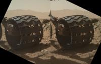
|
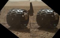
|
Posted by: Eric H. Mar 9 2014, 06:11 PM

Here's a worrying photo from S564.
Posted by: eoincampbell Mar 9 2014, 07:01 PM
I'm sure the team are keeping a close eye on the http://www.midnightplanets.com/web/MSL/image/00562/0562MH0262000003E1_DXXX.html ...
Posted by: fredk Mar 9 2014, 08:17 PM
Nothing new there - that tear has been there for months.
Posted by: Zeke4ther Mar 9 2014, 08:27 PM
These are not the 'droids you are looking for, move along...
Posted by: Gerald Mar 9 2014, 08:54 PM
One of the fissures seems to have propagated a little bit since Sol 513, but not much (distorted Sol 564 inset in Sol 513 subimage):
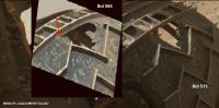
|
Posted by: neo56 Mar 11 2014, 03:30 PM
Curiosity posing in front of Mount Sharp on sol 564:
https://www.flickr.com/photos/105035663@N07/13085290784/
Posted by: atomoid May 19 2014, 09:08 PM
http://www.midnightplanets.com/web/MSL/image/00631/0631MH0002590000203729E01_DXXX.html (http://www.midnightplanets.com/web/MSL/image/00631/0631ML0026110000302549E01_DXXX.html).. didnt see any mention of this elsewhere or i wasnt paying attention..., perhaps it has dropped off by now ...unless its lodged in there whreel well!
EDIT: fell out sometime before http://www.midnightplanets.com/web/MSL/image/00635/0635MH0002590000203765E01_DXXX.html
Posted by: Gerald Jun 22 2014, 09:07 PM
Hole opened in the left middle wheel between Sol 660 and Sol 667:
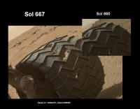
|
Posted by: elakdawalla Jun 22 2014, 09:13 PM
Ouch. I noticed the last time I mapped wheel wear that the middle wheels appeared to be accumulating new tears more rapidly than the front ones.
Posted by: Gerald Jun 22 2014, 10:13 PM
That has been a drive of about 500 meters; thus roughly extrapolated, we should be prepared to about 5 to 10 additional similar tears or holes till Murray Buttes - although we've always to look with precaution on extrapolations.
Not really frightening under normal circumstances; we'll have to get accustomed to it ... and keep the eyes open.
Posted by: climber Jun 23 2014, 08:09 AM
In this case we can see that the place was already damaged so, I guess, it was "easily" removed. Actually, we can't see yet whether the missing part is torn inside the weel or has been lost. Do you think there is any change of loosing a torn part of a weel? If yes, we'll have to look closely in the rear direction to see if we can see it.
Posted by: Gerald Jun 23 2014, 09:58 AM
The upper left fragment (in the image) is evidently torn inside. I didn't find immediate evidence yet, that this does hold for the lower right fragment, too. But the aluminium alloy should be sufficiently ductile to make it more likely, that no large fragment is lost.
A potentially lost fragment should behave similar to a pebble, cause some minor loss of weight of the rover, but without obvious implications to functionality.
Posted by: jmknapp Jun 23 2014, 10:05 AM
A paper http://onlinelibrary.wiley.com/doi/10.1002/rob.20185/abstract has these diagrams of force on the wheels of a MER-type rocker-bogie design going over a step obstacle:
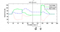
|
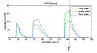
|
At least in that case it looks like the middle wheel experiences the greatest forces & the front wheel has it the easiest. The peak force on the middle wheel is when the rear wheel climbs the step.
Posted by: elakdawalla Jun 23 2014, 03:14 PM
I don't have access to that journal, unfortunately. That's a cool graph. Are the "front" wheels in this journal article on the bogie, or the rocker? I know that the rocker-bogie suspension system performs better bogie-first -- the JPL rovers are all built "backwards" so that if they get into trouble they're better-positioned to extricate themselves. But the graph is labeled "MER" so maybe it is rocker-first.
Posted by: fredk Jun 23 2014, 03:40 PM
That paper states
Posted by: jmknapp Jun 23 2014, 04:57 PM
Weird drive on sol 667--only 1.2m spread out over almost 2 hours. The http://curiosityrover.com/tracking/speedplot.php?drivenum=200 shows it was in four equally-spaced bumps, and http://mars.jpl.nasa.gov/msl/multimedia/raw/?s=667&camera=MAST_ and http://mars.jpl.nasa.gov/msl/multimedia/raw/?s=667&camera=MAHLI took images of the wheels along the way. Worrying about the wheels has been officially deregulated.
It'd be interesting to see 4 images of a particular wheel combined to "unroll" it into a continuous ribbon showing the wear pattern.
Posted by: elakdawalla Jun 23 2014, 05:14 PM
That's not weird, that's a standard wheel-imaging drive -- they do those every few hundred meters in order to monitor damage. They seem to be performing them on weekends for the most part. They recently made a tweak to their wheel-imaging routine: It used to be they took MAHLI images centered on each wheel (6 images), in 4 different positions. Now they are taking images of middle and rear wheels together (so only 4 images total), in 5 different positions, which gives them a more complete survey. They've also added Mastcam and MARDI documentation.
Also, note this talk planned for the 8th Mars conference in Pasadena:
This event is presented in conjunction with the Eighth International Conference on Mars.
The speakers for this event are, John Grotzinger, Mars Science Laboratory project scientist, and Matt Heverley, Curiosity Rover driver
The lecture is free and open to the public. No tickets or reservations are required.
Wednesday, July 16, 7:30 p.m., Beckman Auditorium
I'm not sure I'm going to be able to go, sadly.
Posted by: jmknapp Jun 23 2014, 05:45 PM
Ah, I should have looked back in this thread at some of your wheel maps. Looks like they've been doing this since about January?
As for what they did about it, does it refer to this item from February?: http://www.jpl.nasa.gov/news/news.php?release=2014-055
Posted by: elakdawalla Jun 23 2014, 06:00 PM
Yes, I expect the public event to just be the story behind how they determined they should drive backwards, and drive in valleys instead of on high ground -- a nice story about how you solve an unexpected problem on a distant planet! This story is neat in that it's an engineering problem but understanding how to solve it required very close cooperation with the science team, which is kind of unusual for solving problems with spacecraft.
Posted by: Tom Tamlyn Jun 24 2014, 03:35 AM
Any prospect of a video replay (official or bootleg) of the July 16 talk by Grotzinger and Heverley? It looks as though it might be particularly interesting to our crowd.
Posted by: bobik Jun 24 2014, 06:44 AM
On June 9, the Washington Post featured an http://www.washingtonpost.com/national/health-science/too-bad-theres-no-aaa-on-mars-as-the-curiosity-rover-faces-equipment-trouble/2014/06/09/c055fe54-eb25-11e3-93d2-edd4be1f5d9e_story.html on the MSL wheel issue.
Project scientist John Grotzinger said the wheel issue "quickly became an epic-scale problem for the mission. . . . Its a little like being told youre critically ill. You dont know how much longer you have, but you know it will be a rough road."
By the way, will the wheel design need to be changed for the Mars 2020 mission?
Posted by: jmknapp Jun 24 2014, 10:40 AM
"Critically ill"? Nothing to see here but an "epic-scale problem." Glad they were able to pivot, literally.
Posted by: vikingmars Jun 24 2014, 11:07 AM
Everything you want to know about Martian wheels but are too afraid to ask...
https://archive.org/details/nasa_techdoc_19930008925
A JPL/University of Texas study done in 1991... Enjoy !
Posted by: Gerald Jul 4 2014, 08:23 PM
[Disclaimer: The images of this post are not actual images from Mars.]
This provides an idea of how far you can go until a wheel fails:
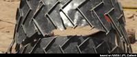
|
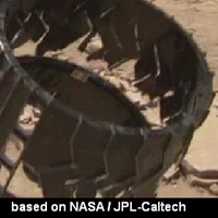
(Screenshots of http://mars.jpl.nasa.gov/participate/students/STEM-job-career-role-models/NASA-science-engineering-women-career-role-model-Amanda-Steffy/.)
Posted by: mcaplinger Jul 4 2014, 09:30 PM
The video is very interesting, but it doesn't describe exactly what is meant by "test to failure". Usually this has a very specific definition for a subsystem test like this. It's not clear to me that the rover would be unable to move with one or more wheels broken even this badly.
Posted by: Gerald Jul 5 2014, 03:04 PM
I'd also assume, that the principle of redundance on each subsystem level is applicable to the wheels, meaning one or two wheels should be redundant to some degree. But I've no link to a paper I could reference to, to underpin this assumption, just some extrapolation from the MER rovers.
... Here a Sol 679 image of a passenger on the right middle wheel:
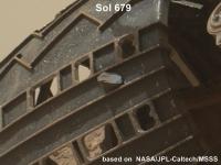
|
Posted by: nprev Jul 5 2014, 08:41 PM
Has there been any attempt made to determine the composition of the rocks that are doing the damage? All I've seen is a reference to an unexpected number of 'small, pointy' rocks in the soil, so I've been assuming that these are shards of basaltic rock that seem to be ubiquitous at every landing site to date save Meridiani.
Posted by: fredk Jul 5 2014, 09:08 PM
They could only do that statistically, since I doubt anyone has identified a particular rock punching a hole in a wheel.
Also it sounded like part of the problem was an underlying surface that didn't "give" when driving over a rock. Perhaps under those circumstances there are enough sufficiently sharp garden-variety pieces of basalt to do the damage.
Posted by: nprev Jul 5 2014, 09:26 PM
Ah, thanks, missed the part about the substrate. Wonder if perhaps the entire area has underlying hard-tack evaporites.
Posted by: Astro0 Jul 6 2014, 05:24 AM
That was really clingy soil on Sol 673. Right centre wheel.
Temporary patching on a few cracks
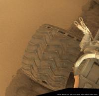
|
Posted by: jmknapp Aug 4 2014, 09:33 AM
Ouch
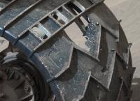
|
Posted by: climber Aug 4 2014, 10:17 AM
They intended to write a nice "JPL" at regular space on the soil. Well, the message will be a bit confused now...
Posted by: anticitizen2 Aug 4 2014, 01:24 PM
The wheels have met a few rocks between Sol 34 and now...
Posted by: fredk Aug 4 2014, 02:51 PM
That gash hasn't changed much over the sols:
http://www.unmannedspaceflight.com/index.php?s=&showtopic=7658&view=findpost&p=208106
Posted by: Harder Aug 4 2014, 03:30 PM
Looking at that picture with the ouch, I realize all of a sudden that mentally Ive moved on from any wheel concerns.
The cleats look fine even though a bit of tincan aluminium came off, so what. My frame of mind is it looks sturdy, good to go for many, many more miles - all as predicted by the UMSF experts (who told me so in no uncertain terms!!) see the thread.
After all these sols the mission is now getting tantalizingly close to the primary science objectives and thats what Im thinking about mostly for MSL.
Posted by: Floyd Aug 4 2014, 03:49 PM
We had been a lot on softer terrain, but the stretch from about sol 690-703 went over some nasty sharp rocks in hard surfaces. Not surprised we did some damage over that time frame.
Posted by: monitorlizard Aug 4 2014, 05:02 PM
I find myself confused over why MSL's wheels have suffered damage but I never heard any reports of Spirit/Opportunity wheel damage. Is it because MSL is so much heavier than the MER rovers or is it because of different wheel designs? Obviously, Opportunity was a much more benign (less rocky) environment for much of its mission, but I don't think you can say that about Spirit. It all makes me wonder if NASA should go back to the MER wheel design, appropriately scaled up for MSL weight, for the 2020 rover.
Posted by: elakdawalla Aug 4 2014, 05:18 PM
The different wheel design is only part of the story. It's mostly because of the terrain. I've heard the caprock at the Curiosity site described as being "like sharks' teeth embedded in concrete." It's not only that the rocks are pointy, but that they don't shift at all when the rover drives over them. Loose rocks sitting on sand get pushed down into the sand as the rover drives over them, substantially mitigating the force they apply to the wheels. Neither of the MERs ever drove over bedrock like this for any substantial amount of time.
Posted by: mcaplinger Aug 4 2014, 05:58 PM
If this had been an option for MSL, it would have been done that way. Simple scaling makes wheel mass go up too much and then there are ripple effects throughout the whole system.
Clearly MSL went a little too far in the lightweighting direction, and I'm sure this will be addressed for 2020, but the problem is more involved than might be immediately thought.
Posted by: Gerald Aug 4 2014, 06:42 PM
With the MSL wheel design the rover can drive on, even if a wheel gets hooked in sharp rocks, by sacrificing part of her beauty. The actuators and structural components are strong enough.
With more robust wheels the probability, that a wheel gets stuck in sharp rocks may be reduced, but likely not to zero. So if a wheel of a potential more robust design gets stuck, nevertheless, how does it get disentangled?
A better design may be possible, but it's better to think twice, before changing a design, which is doing its job, although maybe not perfectly in every aspect.
Posted by: jmknapp Aug 4 2014, 06:51 PM
I was wondering what happens if cracks propagate all the way across, particularly at several points around the circumference. Does it still hold together?
Posted by: Gerald Aug 4 2014, 07:06 PM
Yes, it holds together unless the crack propagates across the cleats along almost all the circumference.
A few posts earlier (Post #217) I've added a link to a video showing were the limits are.
Posted by: PDP8E Aug 4 2014, 09:15 PM
Here is an image from SOL-696 that caught my eye.
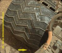
|
At first I thought the rover was shedding something, but after looking at the thing's DN numbers, it was about the same as the soil/rocks out in front of the wheel shadow
I am pretty sure it is sunlight from the top right of the wheel (between the rover body or the big holes at the top of the wheel) shining through a rip that is out of our view.
Posted by: blake Aug 9 2014, 03:09 PM
I've followed this thread since it first started, when the first holes started appearing in the wheels. And I've had a question from the beginning that I hoped would have been mentioned or answered by now. Now that we have gotten to the Hidden Valley, I am just going to ask it:
Do the holes in the surface of the wheel affect mobility on a sandy surface like Hidden Valley? At what point do holes in the thin aluminum surface start to affect driving over 'dune-like' conditions? I know JPL is spelled out in holes, but if the whole wheel surface was like that, would Curiosity have a harder time in the sand? Clearly the JPL holes interact differently with the sand than the rest of the wheel judging by the tracks left in the sand.
There has been many posts (see below for a small selection) about how the wheels will keep on driving despite the damage. I even remember reading that if a wheel was just spokes, or squared off, it would still drive. But it seems to me that the aluminum 'webbing' between the cleats probably help to float the wheel over the sand. I'm not asking to prove anybody wrong or fear-monger, obviously the wheel isn't just going to fall off, stop turning, etc.; just wondering if there's any information on webbing/sand interactions. I just looked through the thread again and didn't see anybody discuss it (is that enough disclaimers?).
They make little to no difference to traction or surface pressure. Remember - it's 899kg across 6 wheels each with basically the same surface contact patch. It wont change significantly with a few dings and dents in it.
Thanks.
Posted by: mcaplinger Aug 9 2014, 04:24 PM
I doubt that the holes at this point affect mobility. But despite many of the historical comments in this thread, it's now obvious that the magnitude of wheel damage was not anticipated, and given the retreat from driving on sand, there is probably something unexpected about that as well. Clearly soil properties and their effect on mobility are very complicated, analysis and testing under Earth conditions can only go so far, and the system is very highly constrained for mass, power, etc.
We'll just have to wait and see how this plays out.
Posted by: Don1 Aug 20 2014, 08:22 AM
Emily has written an excellent blog post http://www.planetary.org/blogs/emily-lakdawalla/2014/08190630-curiosity-wheel-damage.html with a lot of new information about this topic.
My reaction to the article is that the wheel issue seems like a manageable problem as long as the terrain doesn't get worse when we start climbing Mt Sharp. It probably means that Curiosity won't ever drive as far or last as long as Opportunity has, but it doesn't really need to given the proximity of Mt Sharp. And the lab instruments and the drill won't last for ever either.
Fortunately by 2020 there will be a new rover to replace Curiosity.
Posted by: Explorer1 Aug 20 2014, 08:35 AM
There are several drill bits, I recall. And given the paucity of uses for both it and the sample collecting instruments so far, they might well last as long as Oppy's RAT.
Posted by: djellison Aug 20 2014, 02:23 PM
Why would wheel wear have an impact on rover longevity?
Posted by: RoverDriver Aug 20 2014, 03:14 PM
Rover longevity no, but mission longevity probably yes.
Paolo
Posted by: Gerald Aug 20 2014, 04:32 PM
I'm wondering, whether a wheel, severely damaged along the stiffening ring, needs to be the end of the wheel or the driving.
Wouldn't it be possible to intentionally split the inner two thirds completely from the outer third by patiently fatitiguing the remaining cleats (e.g. by driving back and forth over an appropriate rock a sufficiently large number of times); then driving with the outer third of the wheel through the removed inner two thirds, again using Martian rocks as tools?
The journey could be continued with the outer third of the wheel.
Certainly a (crazy) challenge, but did anyone try?
Posted by: elakdawalla Aug 20 2014, 04:40 PM
In testing, they have found that the inner 2/3 of the wheel does, in fact, rapidly shred off of the rest of the wheel once all the chevron-shaped grousers have broken through. They are currently testing driving on the remaining 1/3 of the wheel, which does work. The problem is that to get to the 1/3 wheel state you have to go through a state where the inner 2/3 flaps around while you're driving, endangering the cable bundle that runs along the top of the wheel strut. If a sharp edge of shredded wheel slices into that cable, not only will the wheel possibly become unusable, but the short could affect the motor controller -- which runs wheels, HGA, and mast. Needless to say, they will not take any action that would knowingly risk failure of the motor controller.
Posted by: Gerald Aug 20 2014, 04:51 PM
My hope has been, that the risk could be handled by staying at a well-known location, driving forth and back just several centimeters, plus steering, such that cables remain in safe distance from wheel shreds, until this intermediate state is overcome.
Posted by: fredk Aug 20 2014, 06:12 PM
Damage to cables aside, it's not clear how you could drive the outer 1/3 through the inner 2/3. To be able to do that, you'd need to slice the inner 2/3 open, so it could be at least partially "unwrapped" along its circumference. For example, you could slice between two odometry grousers. But to completely slice through the inner 2/3, you'd need to slice through the inner rim. Most damage is away from the inner rim.
Maybe you could target the inner rim for damage. But then it's not clear if you'd be able to unwrap the inner 2/3 since once it's complely loose you'd be very limited in the forces you could apply to it.
Posted by: Gerald Aug 20 2014, 08:20 PM
That's probably the more tricky ("crazy") part.
An idea would be to use a rock as a tool to slip the 2/3 over the 1/3 ("driving through"). For this to work, the 2/3 needs to be stretched (assuming it cannot be sliced).
The acute angle and the relatively low coefficient of friction between the two wheel parts should help to amplify the torque of the wheel actuator.
The first step would be to find out, whether this experiment is physically possible respecting the material parameters of the alloy and the torque of the actuators.
If it turns out to be physically possible, it's necessary to find out, whether the experiment can be executed in a reliable way.
Since the wheels have been constructed to dampen the landing, and the actuators are rather strong, I'd consider the idea as physically possible, but anything beyond is guesswork, without experiments. That's why I've asked, whether there exists already some experimental experience.
Posted by: serpens Aug 21 2014, 12:06 AM
Somehow I think the extremely competent mission engineers, having access to a wealth of empirical trials data and theoretical considerations will have this matter well in hand and will have considered all options. However the capacity for mitigation is pretty limited and the main value will be in lessons learned and the reminder for future designs that no plan survives contact with the enemy (the enemy in this case being the Martian terrain). However perhaps we should also remind ourselves that the MSL fulfilled the last outstanding mission success criteria when it lasted one year on Mars. Possibly we have all been spoiled by the amazing longevity and transit distance achieved by Opportunity. However Opportunity's achievement should also be considered in light of the nail biting near failure of Spirit in the first few days which was rectified only because some very smart people provided for a low data rate communications back door. This enabled the problem to be identified and rectified in both Spirit and Opportunity. All in all the MSL wheels have done pretty well.
Posted by: algorithm Aug 21 2014, 07:17 PM
IMHO, that's a pretty low expectation. Personally I wouldn't bolt on a nuclear generator just to enable a rover to last the lifetime of a wheel, especially if that wheel did 'pretty well' to last two years.
Posted by: serpens Aug 21 2014, 11:28 PM
I would think the use of a nuclear generator would be a function of the requirement for a stable power level and invulnerability to dust storms rather than longevity. Regardless, if any mission critical part of the MSL gave up the ghost tomorrow the mission would have to be classified as a success having fulfilled prime mission requirements. Still there will be some pretty interesting risk analysis being undertaken in considering the alternatives of driving over hidden valley sand or the wheel damaging environment associated with bypassing the valley.
Posted by: Don1 Aug 22 2014, 01:13 AM
We're years away from wheel disintegration at this point, and it might never happen if the rover is lucky with the terrain. What worries me more is what the project might do to preserve the wheels. Wheel damage is a slow, degenerative disease, but getting stuck in soft sand could stop a mission overnight. Or the rover might get slowed down so much that all the instruments have packed up before we have finished on Mt Sharp.
People praise Opportunity, but they overlook that two of the instruments have gone and their loss means the rover can no longer detect clay minerals, which is a real problem when you are trying to explore clay rich regions.
The reason for the nuclear generator was to allow a wider choice of landing sites, in particular southerly sites like Eberswalde. It also simplifies operations, and makes the rover immune to planet wide dust storms.
Posted by: jmknapp Aug 22 2014, 11:16 AM
Is current to the wheel motors monitored, or possibly some other means (slip signature?) of determining when one of the rover wheels is likely pinned against a rock? If so, could the rover do a little sidestep of some kind?
Posted by: Gerald Aug 22 2014, 11:23 AM
Yes. Here an excerpt of http://www.planetary.org/blogs/emily-lakdawalla/2014/08190630-curiosity-wheel-damage.html:
Posted by: jmknapp Aug 22 2014, 11:58 AM
That'll teach me not to fall behind on Emily's blog.
Posted by: nprev Aug 27 2014, 05:12 AM
Gentle mod note: Guys, MER solar panel cleaning has been exhaustively discussed for years on many, many threads. Let's keep posts relevant to the topic at hand; thanks!
EDIT: Per mcaplinger's suggestion, new topic created http://www.unmannedspaceflight.com/index.php?showtopic=7879 for solar-powered Mars rover issues.
Posted by: algorithm Aug 29 2014, 07:25 PM
I read in earlier posts that the wheels suffered catastrophic failure when the treads had basically been damaged across the entire circumference, and that the wheels would basically split into two parts, one third and two thirds the wheel width.
I have noticed in recent sols that the profile of the stiffening ring/flexure rim is becoming more pronounced as seen from the wheel exterior.
It would seem that subject to exterior pressures this area is indeed a point of weakness and potential tearing, and would therefore bear out the testiing results.
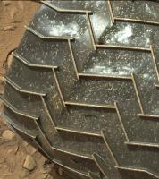
|
Does this seem like a fair assesment?
Edit:When I say increased weakness, I mean increased tensile stress for the outer rim across the wheel width at that point.
Posted by: elakdawalla Aug 29 2014, 07:31 PM
http://www.midnightplanets.com/web/MSL/image/00463/0463MH0262000000E1_DXXX.html I think one of the best pieces of news about the testing program I've heard lately is that they've done such a good job recreating the problem on Earth. That shows they understand the causes, and suggests that mitigation methods that work on Earth to prevent further damage might also work on Mars.
Posted by: algorithm Aug 29 2014, 07:34 PM
As I said, this would bear out the testing results.
Posted by: algorithm Aug 29 2014, 08:00 PM
Lets hope so, in fact i'm sure that they will.
The thing I wonder is, how far does the rover have to travel across what is damaging terrain, to find a traverse/terrain that consistently allows the results of those methods mentioned to become apparent?
We need a guy to rake out the bunkers!
Posted by: jmknapp Aug 31 2014, 12:31 AM
Does the ambient temperature affect the strength/ductility/brittleness of the aluminum wheels much? There can be more than a 100°C swing from day to night temperature.
EDIT: found this http://www.aluminiumdesign.net/why-aluminium/properties-of-aluminium/:
Posted by: serpens Aug 31 2014, 10:48 PM
In the temperature range that Curiosity experiences the change in marginal increase in tensile and yield strength is marginal. While various aluminium alloys differ in response it is really above say 50 C that the effect becomes really noticeable. Certainly this would not even be a consideration as a risk benefit for Curiosity.
Posted by: jmknapp Sep 1 2014, 01:03 AM
Sounds like you're looking at some data. What alloy are the wheels made of?
Posted by: serpens Sep 1 2014, 04:21 AM
I think (relying on memory) that it is 7075-T6 alloy.
Posted by: jmknapp Sep 1 2014, 06:59 PM
Evidently that matters somewhat, as well as the fracture direction:
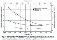
|
Posted by: serpens Sep 2 2014, 12:38 AM
Most of the trials and data for aerospace alloys and tempers has been directed towards aircraft applications where fatigue crack growth rates get a lot of attention. But with Curiosity's wheels we are well outside normal designs and comfort zones and for the thin skin between cleats deterioration will be a function of accumulating penetrative injuries rather than crack growth. The cleats themselves seem to be hanging in there but as I think Paolo mentioned will be subject to repetitive flexing although the frequency of such is anyone's guess. Mars has thrown up an unexpected, damaging terrain that could not possibly have been anticipated from orbital imaging, but overall the mobility system has met all performance expectations. But in the temperature range at Gale there would be no wheel durability advantage in night driving.
Posted by: jmknapp Sep 2 2014, 12:54 AM
Just a note: http://en.wikipedia.org/wiki/Fracture_toughness is not related to fatigue per se.
Posted by: serpens Sep 2 2014, 02:18 AM
I really think that we have to differentiate between the deterioration of the thin skin of the wheels and the cleats. The damage to the skin occurs when an encounter with a shard of rock results in the weight on a wheel being taken completely or primarily by the thin skin rather than a cleat. This seems to result in a localised tear or deformation which weakens that particular area and any further encounter will exacerbate the damage. I stand to be corrected but I do not think that fracture growth is of particular concern given the failure mode. The cleats are a different matter in that they can initially withstand such encounters and the probability of failure (fracture break of the cleat) would seem to be a function of fatigue relating to the number of encounter cycles and encounter geometry for each particular cleat. I don't know to what extent the thin skin contributes to the structural integrity of the cleats and whether deterioration of the skin reduces the number of cycles to failure for the cleats. What I am trying to get at I guess is that even the empirical testing to failure conducted once the terrain and wheel problem was recognised is only indicative. It would be interesting to know though whether that testing indicated that the cleat failure was a catastrophic event (sudden break) or growth of an initial partial crack.
Posted by: Gerald Sep 2 2014, 11:33 AM
Take a wire and bend it several times. In the beginning you won't feel much difference. After a while the surface gets rough, meaning there form lots of cracks; for thick wires you can even hear it, sometimes. Then the wire gets rapidly weaker at one position, since one or more of the cracks grow through the wire. Ductility gets lost, too. The break then occurs rather suddenly.
The cleats should behave much the same. Once the strength starts to decrease in an obvious way due to http://en.wikipedia.org/wiki/Fatigue_(material), more or less sudden failure will follow soon due to rapid growth of a crack.
The skin should reduce one degree of freedom of bending of the cleats (parallel to the circumference), and disperse local forces to several cleats.
Therefore loss of larger areas of the skin won't be an advantage for the cleats.
Posted by: Gerald Sep 10 2014, 11:43 AM
Tears and dents in right central wheel formed hole between http://mars.jpl.nasa.gov/msl-raw-images/msss/00667/mhli/0667MH0002610010203887E01_DXXX.jpg and http://mars.jpl.nasa.gov/msl-raw-images/msss/00744/mhli/0744MH0002610010204500E02_DXXX.jpg:
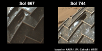
|
Posted by: peter.neaum May 2 2015, 12:23 AM
I just stumbled across this pic.
Amazing.
http://mars.jpl.nasa.gov/msl-raw-images/msss/00971/mhli/0971MH0002620000304268E01_DXXX.jpg
Posted by: elakdawalla May 2 2015, 03:51 AM
Here's a look at the left-middle wheel over time, which is the one I'm most concerned about. Although there have been changes between sol 708 and 962, they're only incremental -- I'm actually pretty pleased with how they look after the Pahrump campaign and a whole lot of driving besides. There are no broken grousers. The grousers to watch closely are the ones between fields 11 and 12 and 13 -- those areas have a lot of tears running a substantial width of the wheel, leaving the grousers with little support except at their ends. So those are the ones that will probably break first, eventually. Hopefully continued careful driving will prevent that from happening for a while.
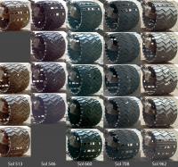
|
Posted by: elakdawalla Jun 8 2015, 04:27 PM
Moved a couple of posts about Mars 2020 wheel design to a http://www.unmannedspaceflight.com/index.php?showtopic=8030 in the http://www.unmannedspaceflight.com/index.php?showforum=80.
Posted by: peter.neaum Oct 10 2015, 05:56 AM
The latest series of images from MSL / Mars Hand Lens Imager / MAHLI camera has several views of the wheels.
From Sol 1127 (40 img): http://mars.jpl.nasa.gov/msl/multimedia/raw/?s=1127&camera=MAHLI
One of the images shows a nasty looking spike of metal jutting into the wheel space. I presume the axle shaft will knock it away / back, before it becomes an issue for the wire bundle.
I was unable to find a better image of the metal spike, but here's a ghastly, tweaked & cropped version (I presume it's a spike and not an optical illusion).
From here:
http://mars.jpl.nasa.gov/msl-raw-images/msss/01127/mhli/1127MH0002640000401794E01_DXXX.jpg
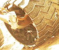
|
Posted by: elakdawalla Oct 12 2015, 03:44 PM
That one has been developing for a while, but it does have quite the inward point. Engineers are justifiably concerned about the possibility of these sharp edges abrading the wire bundles. I actually am having trouble figuring out a scenario in which this one, ripping further, would then straighten in the right way and place to actually scrape a wire bundle; I think it gets to be a more serious problem if (when) grousers start breaking.
Posted by: peter.neaum Oct 13 2015, 10:29 AM
Yes, you're right - when it (or any others) get long enough, they will hit and be bent in/out/forward/aft - but certainly away from the centre of the wheel - which is a very good thing.
Posted by: DeanM Jun 30 2016, 06:01 AM
Been pretty quiet on here: any developments in 'Wheel World'?!
Dean
Posted by: Gerald Jun 30 2016, 11:49 AM
The driving software update appears to have slowed down the wheel degradation. There has been less driving and more science activity. And there haven't been again these sharp and strongly embedded rocks, which caused much of the damage.
I'm not really disappointed about Curiosity being fit for the trip uphill Mt. Sharp.
Posted by: atomoid Jun 30 2016, 09:27 PM
As wheels continue to http://www.midnightplanets.com/web/MSL/image/01386/1386MH0002640000502644E01_DXXX.html and http://www.midnightplanets.com/web/MSL/image/01386/1386MH0002640000502656E01_DXXX.html, lets hope the http://www.midnightplanets.com/web/MSL/image/01386/1386MH0002620000502657E01_DXXX.html survive or well soon end up dead!
Posted by: elakdawalla Jul 1 2016, 04:45 PM
I included this comparison in my most recent update. Degradation has progressed, but only slowly, and there was no acceleration as they went across the Naukluft plateau, as I'd feared. As long as drive distances are relatively short (less than 50 m or so), the rover drivers can prevent a lot of damage by driving around hazards they can see. Not sure how much longer the grousers on the right middle wheel are going to last, but they're hanging on for now.
Full wheel survey sol 1315:
http://planetary.s3.amazonaws.com/assets/images/spacecraft/2016/20160614_wheel_survey_sol1315.jpg
LM wheel over time:
http://planetary.s3.amazonaws.com/assets/images/spacecraft/2016/20160614_wheel_survey_lm.jpg
Posted by: fredk Nov 7 2016, 09:58 PM
I thought something looked a bit odd about the LM wheel on the latest survey, from 1512. Comparing it to an earlier view, from 708, you can pretty clearly see that the grousers near the top have been bent inwards:
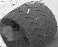
|
They've bent where the skin in between is quite heavily damaged, so I guess it makes sense that this is a weaker point.
I haven't checked carefully to see how far back this bending occured, but judging from Emily's LM compilation it seems to show up at around sol 1315.
(Mods - oops, sorry, I forgot about the pinned wheel thread.) [MOVED - MOD.]
Posted by: elakdawalla Nov 7 2016, 10:20 PM
Oof. Well spotted. I won't have time to look back in time for a bit, but if people want to hunt for where/when this happened, there have been full wheel surveys on 1046, 1127, 1179, 1260/9, 1315, 1434, and 1471. There have also been partial (one position only) surveys on 1182, 1214, 1245, 1287, 1313, 1355, 1380, 1403, 1416, 1435, 1444, 1459, and 1482.
Posted by: peter.neaum Nov 13 2016, 11:17 AM
With thanks to Post #278 from atomoid, above, I found their mentioned link to the site http://www.midnightplanets.com/web/MSL/sols.html
I've always found the http://mars.jpl.nasa.gov/msl/multimedia/raw/ to be quite cumbersome to use - one has to open each day, from each camera, to see what imagery was taken, and then open each thumbnail to get the final image. The http://www.midnightplanets.com/web/MSL/sols.htmlsite is a much better interface and shows all images in a neat grid array (though I'm sure, bandwidth heavy). I presume it's a bit of clever coding - a front end image scraper for the main msl site. It's very good, and, after all these years, I've only just stumbled across it.
Here are the links to the useful MAHLI (and others) images for full wheel surveys days (thanks to E Lakdawalla for pointing them out).
http://www.midnightplanets.com/web/MSL/sol/01046.html http://www.midnightplanets.com/web/MSL/sol/01127.html http://www.midnightplanets.com/web/MSL/sol/01179.html http://www.midnightplanets.com/web/MSL/sol/01260.html http://www.midnightplanets.com/web/MSL/sol/01269.html http://www.midnightplanets.com/web/MSL/sol/01315.html
http://www.midnightplanets.com/web/MSL/sol/01434.html http://www.midnightplanets.com/web/MSL/sol/01471.html
The partial surveys are here:
http://www.midnightplanets.com/web/MSL/sol/01182.html http://www.midnightplanets.com/web/MSL/sol/01214.html http://www.midnightplanets.com/web/MSL/sol/01245.html
http://www.midnightplanets.com/web/MSL/sol/01287.html http://www.midnightplanets.com/web/MSL/sol/01313.html http://www.midnightplanets.com/web/MSL/sol/01355.html
http://www.midnightplanets.com/web/MSL/sol/01380.html http://www.midnightplanets.com/web/MSL/sol/01403.html http://www.midnightplanets.com/web/MSL/sol/01416.html
http://www.midnightplanets.com/web/MSL/sol/01435.html http://www.midnightplanets.com/web/MSL/sol/01444.html http://www.midnightplanets.com/web/MSL/sol/01459.html
http://www.midnightplanets.com/web/MSL/sol/01482.html
The area dented inwards appears to be section 12/13/14.
Posted by: peter.neaum Mar 21 2017, 10:16 PM
And now the first broken grouser, seems to be between 12-13 (as predicted in Post #271!)
https://mars.nasa.gov/news/2017/breaks-observed-in-rover-wheel-treads
https://mars.jpl.nasa.gov/multimedia/images/2017/break-in-raised-tread-on-curiosity-wheel
Images here.
https://mars.nasa.gov/msl/multimedia/raw/?s=1641&camera=MAHLI
This is a very interesting event.
Posted by: atomoid Mar 22 2017, 01:59 AM
A different view of the http://www.midnightplanets.com/web/MSL/image/01641/1641MH0002640000602970E01_DXXX.html: one looks somewhat pushed into the wheel and is slightly severed just outside the hole to the right. Below it a second grouser is severed and displaced quite a bit and is probably the one sticking up in the original image. These are also visible lower down in the next http://www.midnightplanets.com/web/MSL/image/01641/1641MH0002640000602974E01_DXXX.html and looks about right to put the lower one in the right place to peek up over the top in the https://mars.nasa.gov/news/2017/breaks-observed-in-rover-wheel-treads. its sort of grimly funny how the middle wheels take the brunt of the damage, more load-bearing perhaps..
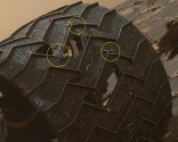
|
Posted by: alan Jun 30 2017, 08:08 PM
An Algorithm Helps Protect Mars Curiosity's Wheels
On level ground, all of the rover's wheels turn at the same speed. But when a wheel goes over uneven terrain, the incline causes the wheels behind or in front of it to start slipping. This change in traction is especially problematic when going over pointed, embedded rocks. When this happens, the wheels in front pull the trailing wheels into rocks; the wheels behind push the leading wheels into rocks. In either case, the climbing wheel can end up experiencing higher forces, leading to cracks and punctures. The treads on each of Curiosity's six wheels, called grousers, are designed for climbing rocks. But the spaces between them are more at risk.
The traction control algorithm uses real-time data to adjust each wheel's speed, reducing pressure from the rocks. The software measures changes to the suspension system to figure out the contact points of each wheel. Then, it calculates the correct speed to avoid slippage, improving the rover's traction. Traction control also addresses the problem of wheelies. Occasionally, a climbing wheel will keep rising, lifting off the actual surface of a rock until it's free-spinning. That increases the forces on the wheels that are still in contact with terrain. When the algorithm detects a wheelie, it adjusts the speeds of the other wheels until the rising wheel is back into contact with the ground.
https://www.jpl.nasa.gov/news/news.php?feature=6887
Powered by Invision Power Board (http://www.invisionboard.com)
© Invision Power Services (http://www.invisionpower.com)