Endeavour Drive - Drivability analysis |

  |
Endeavour Drive - Drivability analysis |
 Sep 26 2008, 11:14 PM Sep 26 2008, 11:14 PM
Post
#346
|
|
|
Member  Group: Members Posts: 910 Joined: 4-September 06 From: Boston Member No.: 1102 |
I'm very impressed with all the analyses so for. However, I wonder about some of the assumptions that small close together ripples are good, and big far apart ripples are bad. If I recall correctly, we drove next to some big ripples that had wide flat half pipes beside them. We certainly took advantage of bedrock with widely space dunes also near by. What we need for driving is wide flat bottomed half pipes, or bed rock, that dont dead end in a ripple crest. I wonder if most of the analyses to date are on too large a scalemultiple ripplesmany pixels. What we need is the steepness of each pixel from context clues or from stereo images. Then you color the flat parts green and the steep parts of the ripple sides red. Then the path is like the mazes in the Sunday paperfollow the green space between the red lines (or white on black) to get to the heart of the maze.
What do you think? -------------------- |
 |
 
|
|
Sep 26 2008, 11:25 PM
Post
#347
|
||
|
Member Group: Members Posts: 530 Joined: 21-March 06 From: Canada Member No.: 721 |
Face on Mars! Face on Mars! 
|
|
|
|
|
|
|
Sep 27 2008, 12:00 AM
Post
#348
|
|
 Senior Member Group: Moderator Posts: 2785 Joined: 10-November 06 From: Pasadena, CA Member No.: 1345 |
QUOTE (Floyd @ Sep 26 2008, 07:14 PM)  I'm very impressed with all the analyses so for. However, I wonder about some of the assumptions that small close together ripples are good, and big far apart ripples are bad. What do you think? I think you're right. If there were a way to estimate the size (amplitude) of the ripple compared to the base it would be much better. I'm running on the assumption that big wide ripples mean big tall crests. Since the route from Victoria to Endeavor is roughly SE, we will need to make a lot of dune crossings. So even if we run south on a big wide half-pipe for a while, we will need to cross the dune crests from time to time (probably much more often than the S trek towards Victoria). I'd like to avoid any dune fields if possible and run over flat easy terrain straight to the destination (or easily detour to any science targets). "Oppy don't surf." (apologies to Apocalypse Now) -Mike -------------------- Some higher resolution images available at my photostream: http://www.flickr.com/photos/31678681@N07/
|
|
|
|
|
Sep 27 2008, 12:13 AM
Post
#349
|
|
|
Member Group: Members Posts: 293 Joined: 22-September 08 From: Spain Member No.: 4350 |
Impressive!
Since it's a mathematical method, it should allow matching the scale between several HiRISE images under different conditions. BTW, I tried to match the distant peaks of Endeavour as seen from Cape Verde with an HRSC image. Is this right? |
|
|
|
|
Sep 27 2008, 01:23 AM
Post
#350
|
||
|
Member Group: Members Posts: 293 Joined: 22-September 08 From: Spain Member No.: 4350 |
QUOTE (Floyd @ Sep 27 2008, 01:14 AM) What do you think? I think that if you keep challenging us, we are going to need to send our own high-res camera to Mars. 
It would need tweaking, but it shows that it can be done. What I did: After blending the original and the slightly blurred copies with the Difference mode, and adjusting brightness and contrast, I kept a copy apart, inverted it, duplicated it, blurred one to 5px, the other to 20px, blended both together with Darken only mode and normalized them. That creates a map where both the dune tops and the exposed bedrock are dark. Then I continued the same method as before with another two copies, but instead of applying a red-yellow-green gradient in the end, I applied a transparent to white gradient. The result is a map where small dunes and bedrock are bright and bigger dunes are transparent. I put that layer on top of the previous and blended it, so only the dune tops were left as dark. Then applied a red-orange-yellow-green gradient and blended it with the original image. (man, it's painful to do these things on a 750MHz) |
|
|
|
|
|
|
Sep 27 2008, 01:49 AM
Post
#351
|
|
 Senior Member Group: Members Posts: 1229 Joined: 24-December 05 From: The blue one in between the yellow and red ones. Member No.: 618 |
wow
wow -------------------- My Grandpa goes to Mars every day and all I get are these lousy T-shirts!
|
|
|
|
|
Sep 27 2008, 02:09 AM
Post
#352
|
|||
|
Newbie Group: Members Posts: 16 Joined: 24-September 08 Member No.: 4351 |
Long time lurker, first time poster.
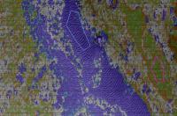
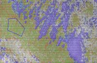
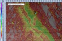
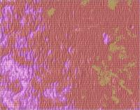
I played around with a texture classifier I have access to at work. I picked a few image attributes I thought might be relevant, and nominated a few regions of example textures into which I wanted the image classified. The two attached images are from a place near the destination, with the classification in color. I thought it nicely segmented out the difficult ripple terrain from the rest. The polygons you see in the images are some of the nominated regions. Lots of things can be tweaked, like the choice of attributes, the example polygons, and the colors. I think I picked too many example areas, since the good areas are a mixture of colors, but the rippled areas area clearly segmented out. The area is near the destination of Edurance, and the image has been rotated - just an artifact of my importation to the processing system that I forgot to undo. I have also tried doing 2d FFTs to extract ripple spacing, orientation, and strength, from the maxima of the spectra. This seems successful, and I'll post some of those images shortly. With these FFT attributes available to the texture classifier, it might be possible to nominate even the different ripple styles and have them individually classified. I have not tried this yet. PS Since this is my first post, I'm not sure if the images will come through OK. If it doesn't, I'll try again! Bill Butler
Attached thumbnail(s)
|
||
|
|
|
||
|
Sep 27 2008, 02:39 AM
Post
#353
|
|||
|
Newbie Group: Members Posts: 16 Joined: 24-September 08 Member No.: 4351 |
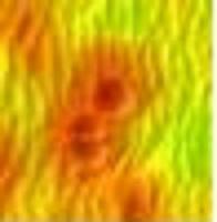
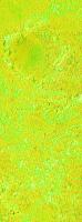
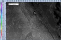
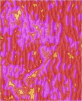
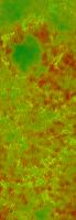
Followup to last post. These images are the raw image I started with, and the standard deviation attribute, similar to what some others were playing with. I think this attribute is a good indication of ripple height/width, which seem to me pretty well correlated with each other.
Bill
Attached thumbnail(s)
|
||
|
|
|
||
|
Sep 27 2008, 02:54 AM
Post
#354
|
|||
|
Newbie Group: Members Posts: 16 Joined: 24-September 08 Member No.: 4351 |
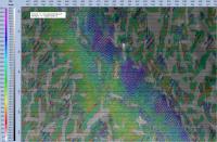
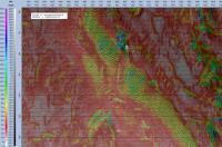
And my last post for the moment - The three 2DFFT attributes. I look for the maximal fft value, other than at the origin, and convert to radial coordinates to compute a distance and angle in frequency space. I take the reciprocal of the frequency distance to get a real distance, and I wasn't sure what to do with the angle - I think I can pretty much leave it alone (is there a rotation or something?). I also plot the absolute value of that maximal fft value. This should be related to the strength of the ripples, but will also be related to their regularity. Strong ripples with varying periodicity will spread out the energy over several frequencies, so the maximum will be lower. I think the standard deviation attribute does a better job of this. On the other hand, if both attributes are given to a classifier, maybe it could distinguish strong regular ripples from more chaotic ones.
The titles of the images are in the upper left hand legend in the picture. Their meanings are: rippledist - reciprocal of the frequency distance. Should be correlated with ripple spacing regardless of orientation. Not calibrated to any units. ripplearg - angle of ripple (in frequency space, but should be something very close to physical space) rippleamp - the absolute value of the maximal FFT sample BTW for these images I did compte every pixel, as the subimage I was using was 2000x1100. WIth a 64x64 fft, this took about 5-10 minutes. Doing every third pixel goes 9x faster and I think give virtually as good information. For the full image, it may even require decimating further, but I could also imagine focusing on the likely rover paths and doing more detail. I see I've run out of space for images for this post. I'll put the last one in the next post. If there is a better way to post these images, let me know. Thanks! Bill
Attached thumbnail(s)
|
||
|
|
|
||
|
Sep 27 2008, 02:56 AM
Post
#355
|
||
|
Newbie Group: Members Posts: 16 Joined: 24-September 08 Member No.: 4351 |
And the last image:
Attached thumbnail(s)
|
|
|
|
|
|
|
Sep 27 2008, 03:01 AM
Post
#356
|
|
|
Senior Member Group: Moderator Posts: 2785 Joined: 10-November 06 From: Pasadena, CA Member No.: 1345 |
QUOTE (wbutler @ Sep 26 2008, 10:09 PM) Long time lurker, first time poster. Welcome, Bill! This is fantastic stuff! Would it be possible to apply this to the terrain area near Erebus and the etched terrain? That area seems some of the gnarliest and it'd be great to do another side-by-side comparisons of the recent generation of methods. I'd really like to see if your technique lights up the bad/scary/curvy dunes. (I think/hope it might) -Mike EXCESS QUOTING REMOVED - ADMIN -------------------- Some higher resolution images available at my photostream: http://www.flickr.com/photos/31678681@N07/
|
|
|
|
|
Sep 27 2008, 04:13 AM
Post
#357
|
|||
 Member Group: Members Posts: 236 Joined: 5-June 08 From: Udon Thani Member No.: 4185 |
QUOTE (wbutler @ Sep 27 2008, 09:54 AM) And my last post for the moment - The three 2DFFT attributes. I look for the maximal fft value, other than at the origin, and convert to radial coordinates to compute a distance and angle in frequency space. I take the reciprocal of the frequency distance to get a real distance, and I wasn't sure what to do with the angle - I think I can pretty much leave it alone (is there a rotation or something?). I also plot the absolute value of that maximal fft value. This should be related to the strength of the ripples, but will also be related to their regularity. Strong ripples with varying periodicity will spread out the energy over several frequencies, so the maximum will be lower. I think the standard deviation attribute does a better job of this. On the other hand, if both attributes are given to a classifier, maybe it could distinguish strong regular ripples from more chaotic ones. Great stuff Bill! My tool works as yet only with the standard deviation, calculating the standard deviation in a 360 degree circle around each pixel, using a range and sample rate which can be configured. I improved a bit on the tool to make it easier to work with and will add some more improvements as I go along, but this standard deviation trick seems to pick out the 'bad' terrain reasonably well. On the other hand, Fourier will get a better indication of the actual 'ripple wavelength', however this only works accurately along the direction of the ripples. I have the feeling that running a FFT along 360 degrees will give you a meaningless answer or at the most something identical to the standard deviation trick.
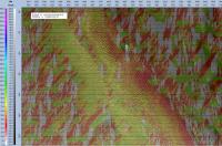
Terrain roughness as indicated by standard deviation goes from green to yellow to orange to red to purple with increasing value (purple is worst). In above example the open bedrock areas are still shown purple, however a lot depends on how you set the resolution, a higher resolution results in a lot more time for calculation, but shows finer details, if I run part of the picture on high resolution the bedrock shows orange or even yellow:
What I am working on now at the moment is to see if I can make the thing show the general direction of the ripples across the image, and I am trying if I somehow can make a distinction in 'driving direction', in other words big long ripples might be okay to drive as long as you remain in the troughs between them (and as long as these troughs remain open for long distances, no cross-ripples), while they are bad if you need to drive across them. So, as we know the 'required direction' to the destination from every position in the picture, it is possible to see how this translates in terrain classification. Once I get more results of this, I'll show them. Just to get an impression where we are at the moment, maybe it would be worthwhile if somebody posted one image which we can then all analyze with the various tools, each tool will probably tell a different story but that only makes it more interesting as every trick seems to indicate one specific part and if we put them all together (preferably on a picture showing route already traveled) it is easier to see which tool tells us what. Note it is definitely not a competition to see which trick is 'best' as each has its own specialization, but if we for instance find a route which is voted 'green' in all analyzing methods, that's perfect, the less votes a route gets, the more the 'real' drivers have to take care. Finally, in the end, it all comes down to human eyes, but the tools will help for a first classification of the terrain I guess. Regards, Geert. |
||
|
|
|
||
|
Sep 27 2008, 04:35 AM
Post
#358
|
|
|
Senior Member Group: Moderator Posts: 2785 Joined: 10-November 06 From: Pasadena, CA Member No.: 1345 |
QUOTE (Geert @ Sep 27 2008, 12:13 AM) Just to get an impression where we are at the moment, maybe it would be worthwhile if somebody posted one image which we can then all analyze with the various tools, each tool will probably tell a different story but that only makes it more interesting as every trick seems to indicate one specific part and if we put them all together (preferably on a picture showing route already traveled) it is easier to see which tool tells us what. I've been using the Erebus to Etched terrain image. Available here (November 29 MRO Image Release thread, Post 33) -Mike -------------------- Some higher resolution images available at my photostream: http://www.flickr.com/photos/31678681@N07/
|
|
|
|
|
Sep 27 2008, 04:50 AM
Post
#359
|
|
|
Senior Member Group: Members Posts: 1229 Joined: 24-December 05 From: The blue one in between the yellow and red ones. Member No.: 618 |
I wonder if this enthralling study of MER route prognostication should be ensconced in its own thread, rather than interspersed with routine progress reports for Oppy? Los Moderates?
-------------------- My Grandpa goes to Mars every day and all I get are these lousy T-shirts!
|
|
|
|
|
Sep 27 2008, 04:54 AM
Post
#360
|
||
|
Senior Member Group: Moderator Posts: 2785 Joined: 10-November 06 From: Pasadena, CA Member No.: 1345 |
Whoo-hoo! The differential-shift method is working!
Following Circum's suggestion, the key is to remove the brighter-toned bedrock and replace with a slightly darker gray (color tone of sl. shaded dunes) that average out with remnant bright edges of bedrock. This averages out after Gaussian to make the bedrock cancel out during the differential shift. (I played with shifting values and Gaussian blur to see which shift gave the brightest response for big dunes with a 22 pixel wavelength. Before blurring the brightest post-differential response was a 15 pixel shift to the E. After a 4 pixel Gaussian blur, the brightest response was 10 pixel. The reason is that the dunes are not symmetrical, but the Gaussian blur smooths them out enough.) Bedrock areas with big dunes are also getting indicated as "bad". But bedrock areas with small dunes are getting flagged as "good". Here is the result:
And here is the recipe (big dune wavelength about 22 pixels): 1) Select the brightest bedrock areas (I cheated and used the magic wand function with a tolerance of "10", it gets a few dune tops but it's OK) 2) Recolorize to a darker dune-shade gray 3) Copy layer 4) Gaussian layer each layer (4 pixels, about 0.2 dune wavelengths) 5) Shift one layer to E (orthogonal to parallel dunes) by 0.5 dune wavelengths (10 pixels) 6) Take differential 7) Merge layers 8) Gaussian blur to 30 pixels (1.5 dune wavelengths) 9) Contrast levels. Darkest = black, brightest = white 10) Colorize green=black, red = white 11) Overlay (multiply) with original image. -Mike -------------------- Some higher resolution images available at my photostream: http://www.flickr.com/photos/31678681@N07/
|
|
|
|
|
|
|

|
Lo-Fi Version | Time is now: 29th May 2024 - 05:51 PM |
|
RULES AND GUIDELINES Please read the Forum Rules and Guidelines before posting. IMAGE COPYRIGHT |
OPINIONS AND MODERATION Opinions expressed on UnmannedSpaceflight.com are those of the individual posters and do not necessarily reflect the opinions of UnmannedSpaceflight.com or The Planetary Society. The all-volunteer UnmannedSpaceflight.com moderation team is wholly independent of The Planetary Society. The Planetary Society has no influence over decisions made by the UnmannedSpaceflight.com moderators. |
SUPPORT THE FORUM Unmannedspaceflight.com is funded by the Planetary Society. Please consider supporting our work and many other projects by donating to the Society or becoming a member. |
|