Endeavour Drive - Drivability analysis |

  |
Endeavour Drive - Drivability analysis |
 Oct 25 2008, 03:52 PM Oct 25 2008, 03:52 PM
Post
#661
|
||
 Member  Group: Members Posts: 236 Joined: 5-June 08 From: Udon Thani Member No.: 4185 |
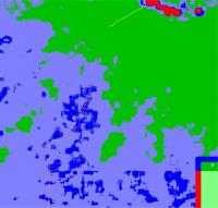
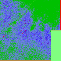
Full Hires STDEV analyzes centered on sol 1687 position with past track in yellow and West Spur route marked in orange.
I agree with Tesheiner that the entrance point of the W-Spur route is a bit uncertain, also from the point of moving towards Endeavour the W-Spur still doesn't make sense to me mathematically, if I try to compile an optimal route, based on Mike's driving-assesments, the software always seems to favour the SW route as the fastest route from the 1687 position (see also my earlier post). I still expect they intend to turn south or SSE later and head for the SW route, although that one also has some nasty spots it gets you quicker across the debris zone and enroute to Endeavour. The W-Spur route would only make sense if you lose a wheel, or there might be scientific reasons to head for it. Next driving days will be interesting.. |
|
 |
 
|
|
|
Oct 25 2008, 04:12 PM
Post
#662
|
||
 Senior Member Group: Moderator Posts: 2262 Joined: 9-February 04 From: Melbourne - Oz Member No.: 16 |
FYI - Here is Tesheiner's route map with my colour coding. Dangerous seas ahead...
Attached thumbnail(s)
-------------------- |
|
|
|
|
|
|
Oct 27 2008, 12:39 AM
Post
#663
|
||
|
Solar System Cartographer Group: Members Posts: 10172 Joined: 5-April 05 From: Canada Member No.: 227 |
This is my guess for the route to come.
Phil
-------------------- ... because the Solar System ain't gonna map itself.
Also to be found posting similar content on https://mastodon.social/@PhilStooke Maps for download (free PD: https://upload.wikimedia.org/wikipedia/comm...Cartography.pdf NOTE: everything created by me which I post on UMSF is considered to be in the public domain (NOT CC, public domain) |
|
|
|
|
|
|
Oct 27 2008, 01:53 AM
Post
#664
|
||
 Senior Member Group: Moderator Posts: 2785 Joined: 10-November 06 From: Pasadena, CA Member No.: 1345 |
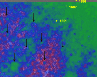
There a couple things ahead that look like they might be mini-Erebus-style dust traps. These seem to have a circular shape with a smoother interior (more green color), a rock pavement rim, and in the HiRise images they seem to be just slightly darker than the surrounding sands.
They show up nicely in my terrain model probably due to the color shading levels. (They also show up in Fran Ontanaya's terrain model). I've indicated a few of the more obvious ones with dark arrows (there are more in there...) in the area Oppy is about to enter in this blink animation:.
(click to animate) Digging back through Oppy's historical route, I didn't see any similar type terrain patterns that Oppy passed through. (There were a few close by to Oppy's route but I couldn't find any corresponding Navcam images). So I have no idea if this is a real concern or not... -Mike -------------------- Some higher resolution images available at my photostream: http://www.flickr.com/photos/31678681@N07/
|
|
|
|
|
|
|
Oct 27 2008, 11:06 AM
Post
#665
|
||
|
Member Group: Members Posts: 236 Joined: 5-June 08 From: Udon Thani Member No.: 4185 |
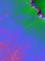
STDEV analyses for SW driving direction with actual traject (yellow) till sol 1691 and route proposed by Phil Stooke (orange).
I agree that this indeed looks like the most likely route Oppy will take and it looks like the smoothest route possible (although not necessarily the quickest), but Mike is correct that there are some features there which require attention, maybe old craters filled with dust or something similar. I wish Paolo and his colleagues good luck on this route, and keep your eyes open ;-)
After the final turn to SE on the route there might be some nasty parts, little bit too much red in the picture although there doesn't seem to be much choice... only possible option might be to continue SW or WSW, keeping to the west of the big red area's and then turning a bit more south to get to the green, this is a slightly longer route but avoids the nasty red patches after the turn to SE. |
|
|
|
|
|
|
Oct 27 2008, 03:54 PM
Post
#666
|
||
|
Member Group: Members Posts: 111 Joined: 14-March 05 From: Vastitas Borealis Member No.: 193 |
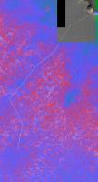
Not a new analysis here, but a new dimension to support (I hope) other analyses.
A red-blue anaglyph showing our probable future route, the so called West Spur, and bedrock to the east. I have put it into 25-% perspective (not geometrically correct) for the effect and to save space. The original images are half resolution of the HiRise images (the scale 0.5 m/pix is retained in the bottom in E-W direction). Oppy's current location is at the upper right corner. In the southwest there seems to be an alarmingly deep eroded crater, the big smooth area in the southern part of the West Spur route. Might be wiser to skirt around it?
Attached thumbnail(s)
|
|
|
|
|
|
|
Oct 27 2008, 04:41 PM
Post
#667
|
|
|
Senior Member Group: Moderator Posts: 2785 Joined: 10-November 06 From: Pasadena, CA Member No.: 1345 |
QUOTE (marswiggle @ Oct 27 2008, 11:54 AM)  Not a new analysis here, but a new dimension to support (I hope) other analyses. Very cool! (nice pun, too!) How did you create the anaglyph? -------------------- Some higher resolution images available at my photostream: http://www.flickr.com/photos/31678681@N07/
|
|
|
|
|
Oct 28 2008, 01:42 AM
Post
#668
|
||
|
Member Group: Members Posts: 111 Joined: 14-March 05 From: Vastitas Borealis Member No.: 193 |
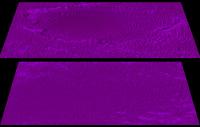
Seems that I'm after all going to analyse... To put things still more into perspective (maybe a pun too), here's comparison of Erebus (top) and the above mentioned southern ghost crater presented in a similar fashion, in the same scale (here 75 % of full-res in E-W dir). The latter crater being very eroded, it's a bit hard to judge its dimensions, but I'm getting the idea that it's slightly less deep of the two though.
I have used the HiRISE images PSP_001414_1780 and PSP_009141_1780 (using OpenEV to export samples, StereoPhotoMaker to make anaglyphs). They were acquired at one Martian year interval and have a very similar lighting and shading. And they make a spectacular stereo pair, actually I think the effect is rather exaggerated, but very suitable for this topography. My using of the (pseudo) perspective as shown is just an idea meant to more easily handle and visualize these images while at the same time to keep the resolution in the E-W direction as good as possible, obviously of central importance in this case. I'll perhaps post some more (full-res or larger) anaglyphs after Oppy has chosen her way between the ripples.
Attached thumbnail(s)
|
|
|
|
|
|
|
Oct 28 2008, 02:08 AM
Post
#669
|
|
|
Senior Member Group: Moderator Posts: 2785 Joined: 10-November 06 From: Pasadena, CA Member No.: 1345 |
That is a very interesting effect. Smoother terrain seems to be at a lower perspective depth.
How does it treat the flat terrain just north of Erebus crater? (Seen in Sol 624, here) Do you think it would be possible to use the perspective view of the two acquired images to create a "flat" 2D terrain model (with coloring based on perspective depth)? (IIRC, this type of analysis is actually closer to what the rover drivers are using.) -Mike -------------------- Some higher resolution images available at my photostream: http://www.flickr.com/photos/31678681@N07/
|
|
|
|
|
Oct 28 2008, 02:27 AM
Post
#670
|
|
|
Member Group: Members Posts: 104 Joined: 1-June 08 Member No.: 4172 |
Essentially you would be creating a DEM from the data, something that isn't exactly very easy to do. While our eyes can easily determine the "distance" between a point in two stereo images, a computer can't very easily do the same. However, various approximations can be used that would be perfectly acceptable here. With any of these (most have to do with STDEV or variance analysis between the images) one quickly runs into an issue in that the overall elevation of the land can vary significantly across the image, causing both incorrect colors and incorrect matching between images. Applying a high-pass filter should do the trick, though. This is what I experimented with way back here. However, then I did not have the capability to easily extract large areas of the image and work with them in PS/GIMP or PIL/ImageMagick.
|
|
|
|
|
Oct 28 2008, 03:40 AM
Post
#671
|
||
|
Member Group: Members Posts: 111 Joined: 14-March 05 From: Vastitas Borealis Member No.: 193 |
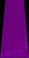
One last image at JuraMike's request. (It's pretty daunting work to make custom anaglyphs in this way.)
The stretch from Viking & Voyager to Erebus north. Purgatory is visible in between. This time full res scale E-W (in the image bottom) and about 40 % scale lengthwise, again with an arbitrary perspective to reduce size. A problem rendering the images less usable for DEMs is apparent: a slanting 'slash' through the image center that appears to shift the left side 'higher', or nearer to viewer, than the right side. In the otherwise pretty flat portion of the landscape this is quite striking feature. I think it's an artefact related to the map projection.
Attached thumbnail(s)
|
|
|
|
|
|
|
Oct 28 2008, 03:41 AM
Post
#672
|
|
|
Senior Member Group: Moderator Posts: 2785 Joined: 10-November 06 From: Pasadena, CA Member No.: 1345 |
QUOTE While our eyes can easily determine the "distance" between a point in two stereo images, a computer can't very easily do the same. However, various approximations can be used that would be perfectly acceptable here. With any of these (most have to do with STDEV or variance analysis between the images) one quickly runs into an issue in that the overall elevation of the land can vary significantly across the image, causing both incorrect colors and incorrect matching between images. I'm wondering if it could be done semi-manually: 1)The red-blue patterns get separated into two greyscale images. 2) The modeler determines which is going to be the "back" part of the image and lines up the images so there is minimal coordinate change for the back part. (This is where the modeller also picks a "typical" terrain in the image.) 3) An image combination (multiply, darken, lighten, invert one then do stuff??) is made that highlights the differences. 4) The whole thing gets Gaussian blurred (and rescaled, contrast enhanced, colorized, etc.) 5) Overlay onto HiRise hi-res image. This would be a real similar process to the shift-differential recipe BUT it uses two separate HiRise images from different angles to get topographic variation rather than just a pattern shift variation. Might give new information that could be used alone or combined with one or all the other terrain models. -Mike -------------------- Some higher resolution images available at my photostream: http://www.flickr.com/photos/31678681@N07/
|
|
|
|
|
Oct 28 2008, 03:54 AM
Post
#673
|
|
|
Senior Member Group: Moderator Posts: 2785 Joined: 10-November 06 From: Pasadena, CA Member No.: 1345 |
QUOTE (marswiggle @ Oct 27 2008, 10:40 PM) One last image at Juramike's request. (It's pretty daunting work to make custom anaglyphs in this way.) This is getting exciting. One thing that is NOT apparent is the smooth flat area that Oppy crossed on Sol 624. It doesn't look like a dust trap in this image, nor did it look like a dust trap in Oppy's Navcam image. (I'm thinking this technique might be helpful for spotting slightly lower depressions that could hold poofy dust.) The next few Sol's images from Oppy can be compared to your earlier images of the W Spur route region. Was this area also modeled by jekbradbury? -Mike -------------------- Some higher resolution images available at my photostream: http://www.flickr.com/photos/31678681@N07/
|
|
|
|
|
Oct 28 2008, 03:32 PM
Post
#674
|
||
|
Senior Member Group: Moderator Posts: 2785 Joined: 10-November 06 From: Pasadena, CA Member No.: 1345 |
Sol 1691 Predicted vs. Actual from the Shift-Differential Terrain model (pretty good!) using a crop of Ant103's image:
I'll try to do a better comparison when the Navcam and Pancam images (for soil type comparisons) get loaded onto the MER Opportunity homepages. -Mike -------------------- Some higher resolution images available at my photostream: http://www.flickr.com/photos/31678681@N07/
|
|
|
|
|
|
|
Oct 28 2008, 05:23 PM
Post
#675
|
|
|
Member Group: Members Posts: 877 Joined: 7-March 05 From: Switzerland Member No.: 186 |
-------------------- |
|
|
|
|

|
Lo-Fi Version | Time is now: 30th May 2024 - 06:37 PM |
|
RULES AND GUIDELINES Please read the Forum Rules and Guidelines before posting. IMAGE COPYRIGHT |
OPINIONS AND MODERATION Opinions expressed on UnmannedSpaceflight.com are those of the individual posters and do not necessarily reflect the opinions of UnmannedSpaceflight.com or The Planetary Society. The all-volunteer UnmannedSpaceflight.com moderation team is wholly independent of The Planetary Society. The Planetary Society has no influence over decisions made by the UnmannedSpaceflight.com moderators. |
SUPPORT THE FORUM Unmannedspaceflight.com is funded by the Planetary Society. Please consider supporting our work and many other projects by donating to the Society or becoming a member. |
|