First drill stop: John Klein in Yellowknife Bay, Site 6, Sol 166-271, January 23-May 12, 2013 |

  |
First drill stop: John Klein in Yellowknife Bay, Site 6, Sol 166-271, January 23-May 12, 2013 |
 Feb 9 2013, 01:46 PM Feb 9 2013, 01:46 PM
Post
#256
|
|
 Senior Member  Group: Members Posts: 2428 Joined: 30-January 13 From: Penang, Malaysia. Member No.: 6853 |
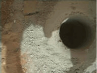
I now think that the perceived depth is is not as important as I first imagined... I suspect the hole still has a large quantity of tailings inside it. This because I believe that the drill test has actually reached very close to its maximum depth of around 50 mm (2"). My reasoning behind this assumption is that it appears that the 'Forward Sample Chamber' of the drill sleeve has left a smooth 'disk like' impression on the mound of tailings surrounding the hole, this smoothing effect stops abruptly a short distance from the hole in approximately the position I would expect considering the short chamfered lead and inward tapered profile of the F.S. Chamber. However, as always such interpretations are open for debate

|
 |
 
|
|
Feb 9 2013, 01:59 PM
Post
#257
|
||
|
Senior Member Group: Members Posts: 2346 Joined: 7-December 12 Member No.: 6780 |
Some Sol 182 MAHLI focussing (size 180%):
I don't know how to accurately infer the quantity of tailings inside the hole by vision. |
|
|
|
|
|
|
Feb 9 2013, 05:34 PM
Post
#258
|
|
 Member Group: Members Posts: 161 Joined: 12-August 12 From: Hillsborough, NJ Member No.: 6546 |
I love those! That is such a good idea!
-------------------- |
|
|
|
|
Feb 9 2013, 06:32 PM
Post
#259
|
||
|
Senior Member Group: Members Posts: 2346 Joined: 7-December 12 Member No.: 6780 |
Thanks! Nice, when others like the same things.
Here a preliminary before/after blink for the second drill hole. It is based on a slightly rotated sol 180 and a sol 182 MAHLI image.
The high resolution version of the final blink seems to be not yet downlinked. |
|
|
|
|
|
|
Feb 9 2013, 06:37 PM
Post
#260
|
|
 Senior Member Group: Members Posts: 4246 Joined: 17-January 05 Member No.: 152 |
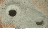
QUOTE (jmknapp @ Feb 8 2013, 10:38 PM)  0180MH0146001000E1_DXXX 2013 FEB 07 01:46:35 UTC XYZ [ 0.561 444.523 -17.372 ] roll -4.39, pitch 4.69, yaw 47.94 0180MH0146001001E1_DXXX 2013 FEB 07 01:49:36 UTC XYZ [ 0.566 444.527 -17.371 ] roll -4.38, pitch 4.70, yaw 48.12 Thanks again, Joe, those are just what we need. A displacement of 6.5 mm and a distance from MH to hole of 14.9 cm (from hole angular diameter and MH fov), together with a directly measured parallax angle of 0.15 degrees between rim and bottom, then gives 0.93 cm for depth from rim to top of tailings in hole. An alternative method uses just the sol 180 MR image. The distance (using angular diameter and fov) was about 229 cm. The angle corresponding to the projected hole depth can be measured straight from the image as 0.15 degrees (that's just the angular depth of the far side of the hole). Using Joe's elevation angle of -49.19 degrees, that can be de-projected into an actual depth, assuming a vertical drill hole, of 0.89 cm. Both of these are well below the stated drilling depth of 2 cm, so we can estimate that the tailings are around 1 cm deep. Like Gerald says, the new MH image lets us directly compare this to the depth of the new hole. |
|
|
|
|
Feb 9 2013, 07:24 PM
Post
#261
|
|
|
Senior Member Group: Members Posts: 2346 Joined: 7-December 12 Member No.: 6780 |
Tough work, Fred!
So by assuming a cylindrical hole with radius 8mm we get a volume of about 2 cubic centimeter of tailings in the first hole (V = r² x pi x h). The depth of the second hole from rim to top of tailings should be near 2.0 cm; if the hole turns out to be actually 5cm deep, as Paul suggested, we get a tailing depth of 3cm and a tailing volume in the hole of about 6 cm³. This was the easier part. |
|
|
|
|
Feb 9 2013, 08:14 PM
Post
#262
|
||
|
Senior Member Group: Members Posts: 2346 Joined: 7-December 12 Member No.: 6780 |
Now, a before/after blink based on two Sol 182 MAHLI images, taken from almost the same position, is available:
A size adjustment of about 0.5% was necessary. |
|
|
|
|
|
|
Feb 9 2013, 08:52 PM
Post
#263
|
|
|
Senior Member Group: Members Posts: 1074 Joined: 21-September 07 From: Québec, Canada Member No.: 3908 |
More info about the drilling in this press release.
The hole is 1.6 cm wide and 6.4 cm deep. |
|
|
|
|
Feb 9 2013, 09:41 PM
Post
#264
|
|
|
Senior Member Group: Members Posts: 1043 Joined: 17-February 09 Member No.: 4605 |
Given that this drill will have undergone test and trials to the nth degree, can we safely assume that the drilling resistance (based on the relationships of penetration depth for revolutions, force, torque etc) can provide an accurate assessment of the cohesion or 'hardness' of this rock?
|
|
|
|
|
Feb 9 2013, 10:00 PM
Post
#265
|
|
|
Member Group: Members Posts: 890 Joined: 18-November 08 Member No.: 4489 |
from sol 182
the hand cam has some Z-axis depth maps -- mind you they are jpg's so... http://mars.jpl.nasa.gov/msl/multimedia/ra...mp;camera=MAHLI --- http://mars.jpl.nasa.gov/msl/multimedia/ra..._DXXX&s=182 http://mars.jpl.nasa.gov/msl-raw-images/ms...0007S0_DXXX.jpg and http://mars.jpl.nasa.gov/msl-raw-images/ms...0003S0_DXXX.jpg |
|
|
|
|
Feb 9 2013, 10:15 PM
Post
#266
|
||
|
Senior Member Group: Members Posts: 2346 Joined: 7-December 12 Member No.: 6780 |
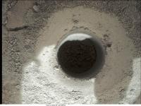
An image not quite trivially composed of the two sol 182 MAHLI images "overexposed" and this one:
So the floor of the second hole becomes visible. |
|
|
|
|
|
|
Feb 9 2013, 10:26 PM
Post
#267
|
|
|
Senior Member Group: Members Posts: 2511 Joined: 13-September 05 Member No.: 497 |
QUOTE (serpens @ Feb 9 2013, 02:41 PM) ...can we safely assume that the drilling resistance (based on the relationships of penetration depth for revolutions, force, torque etc) can provide an accurate assessment of the cohesion or 'hardness' of this rock? Perhaps grossly, but given all the things the drill has to do, I suspect that making this sort of measurement was secondary at best. See http://www.esmats.eu/amspapers/pastpapers/pdfs/2010/okon.pdf for a very interesting and detailed account of the drill mechanism design. -------------------- Disclaimer: This post is based on public information only. Any opinions are my own.
|
|
|
|
|
Feb 9 2013, 11:00 PM
Post
#268
|
|
|
Forum Contributor Group: Members Posts: 1372 Joined: 8-February 04 From: North East Florida, USA. Member No.: 11 |
It's amazing what the designers had to think of to cover as many bad situations as possible and for the general day to day use.
|
|
|
|
|
Feb 10 2013, 12:05 AM
Post
#269
|
||
|
Senior Member Group: Members Posts: 2346 Joined: 7-December 12 Member No.: 6780 |
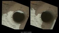
MAHLI Sol 182 stereo:
Shadows may need some practice. |
|
|
|
|
|
|
Feb 10 2013, 12:08 PM
Post
#270
|
||
|
Senior Member Group: Members Posts: 2346 Joined: 7-December 12 Member No.: 6780 |
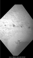
Sol 182 ChemCam blink:
|
|
|
|
|
|
|

|
Lo-Fi Version | Time is now: 28th April 2024 - 01:02 AM |
|
RULES AND GUIDELINES Please read the Forum Rules and Guidelines before posting. IMAGE COPYRIGHT |
OPINIONS AND MODERATION Opinions expressed on UnmannedSpaceflight.com are those of the individual posters and do not necessarily reflect the opinions of UnmannedSpaceflight.com or The Planetary Society. The all-volunteer UnmannedSpaceflight.com moderation team is wholly independent of The Planetary Society. The Planetary Society has no influence over decisions made by the UnmannedSpaceflight.com moderators. |
SUPPORT THE FORUM Unmannedspaceflight.com is funded by the Planetary Society. Please consider supporting our work and many other projects by donating to the Society or becoming a member. |
|