ROVER WHEELS: Monitoring changes over time, NOTE: Read back through the thread to avoid repeating misconceptions |

  |
ROVER WHEELS: Monitoring changes over time, NOTE: Read back through the thread to avoid repeating misconceptions |
 Dec 8 2013, 08:22 PM Dec 8 2013, 08:22 PM
Post
#91
|
|||
|
Senior Member  Group: Members Posts: 2346 Joined: 7-December 12 Member No.: 6780 |
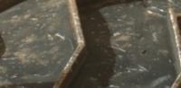
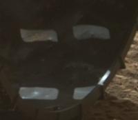
I'd like to see more emphasis on the wheels as a science instrument. Streaks, scratches, dents, holes, tears can be seen as measurements.
Here just some simplified ideas: Probably almost everyone working in mineralogy is best-familiar with determining scratch resistance or using streak plates. The frequency of scratches tells something about the abundancy of mineral grains harder than the aluminium alloy; streaks tell about cementation or about minerals softer than the alloy.
More advanced are macroindentation tests, e.g. Brinell hardness tests. From known force, Brinell hardness of the wheel, and observed indentation the diameter of the indentor can be determined. The shape of indentations can e.g. be inferred from the shape of shadows.
From known penetration and fracture propagation thresholds, lower bounds of the loads causing penetration can be inferred. From the driven distance the frequency per mars surface area can be calculated. So there are quantifyable data. Monitored wheel data could e.g. be used to cross-check a simulation of the mission. (Both images are regions of sol 476 MAHLI images, credit: NASA/JPL-Caltech/MSSS) |
||
 |
 
|
||
|
Dec 8 2013, 08:58 PM
Post
#92
|
|
|
Senior Member Group: Members Posts: 1582 Joined: 14-October 05 From: Vermont Member No.: 530 |
QUOTE (Gerald @ Dec 8 2013, 04:22 PM)  The frequency of scratches tells something about the abundancy of mineral grains harder than the aluminium alloy; streaks tell about cementation or about minerals softer than the alloy. Alloy? It's aluminum oxide from anodizing, right? |
|
|
|
|
Dec 8 2013, 09:28 PM
Post
#93
|
|
|
Senior Member Group: Members Posts: 2346 Joined: 7-December 12 Member No.: 6780 |
The very surface will be oxidized.
I've mainly been referring to the metal below the oxidized layer, which M.Caplinger suspected to be 7075 aluminium alloy, consisting of aluminium, zinc, magnesium, and copper. Pure aluminium is rarely used. Remains the question about the scratch resistance of the oxide layer. |
|
|
|
|
Dec 9 2013, 02:08 AM
Post
#94
|
|
|
Senior Member Group: Members Posts: 1043 Joined: 17-February 09 Member No.: 4605 |
Well you are certainly thinking well outside the box there Gerald and full marks for that although I honestly cannot see any real utility in your suggestion. I guess that the hardness of the anodized layer will have been assessed although you would be pretty safe thinking it to be 7 < <9 (MOHS). Basalt has a MOHS of around 7 but the punctures in the wheel would be caused by small cross sectional contact where the effect on the basalt would be compression. There is no real time visual monitoring so no information available on when or where an incident (scratch, rear, puncture or crazing) occurred, or the dynamics. The anodized coating will have a different coefficient of thermal expansion than the underlying aluminium so there could be a degree of crazing caused by the Martian temperature variations which at the image resolution available would muddy the waters.
|
|
|
|
|
Dec 9 2013, 02:39 AM
Post
#95
|
|
|
Founder Group: Chairman Posts: 14432 Joined: 8-February 04 Member No.: 1 |
QUOTE (Gerald @ Dec 8 2013, 12:22 PM) I'd like to see more emphasis on the wheels as a science instrument. Streaks, scratches, dents, holes, tears can be seen as measurements. However - we will never know what they are a measurement of. Which rock/soil/pebble etc cause what damage. I'm afraid whilst your enthusiasm for this is admirable - there really isn't a legitimate means to extract quantitative data from this. |
|
|
|
|
Dec 9 2013, 11:00 AM
Post
#96
|
|
|
Senior Member Group: Members Posts: 2346 Joined: 7-December 12 Member No.: 6780 |
QUOTE (serpens @ Dec 9 2013, 03:08 AM) ... I honestly cannot see any real utility in your suggestion ... Let me just pick out one simple hypothetical(?) example, because elaborating everything is beyond my possibilities: Imagine a green streak on a wheel. My first association would be malachite, although unlikely on Mars. The wheels can look beneath the dust all along the drive, whereas the cameras can't. If a dent is associated with the streak this may give an estimate of the shape of the peak which caused the streak, useful when driving back for detailed investigation. Here some surface parameters (to be applied to macroscopic features), which could be checked for their effect on the wheels, and possibly back-projected from wheel damage. Just to inspire people to make more of it. I'll (by default) return to monitoring/image processing. |
|
|
|
|
Dec 9 2013, 04:05 PM
Post
#97
|
|
|
Founder Group: Chairman Posts: 14432 Joined: 8-February 04 Member No.: 1 |
QUOTE (Gerald @ Dec 9 2013, 03:00 AM) If a dent is associated with the streak this may give an estimate of the shape of the peak which caused the streak, useful when driving back for detailed investigation. Let's say we have an 80m drive, at the end of which something like what you say is visible. Where is it? Where on the 80m drive? There's no way of knowing. moreover you can only see perhaps 40% of each wheel, possibly less, from MAHLI at the end of any particular drive. So a situation may occur where we have one of your streaks visible on the wheel....and it might have actually occurred several drives previously - several hundred meters ago. How are you going to find it. Furthermore - anything a rear wheel runs over....has already been run over twice by the wheels in front. Again - whilst your enthusiasm for this is admirable, I'm afraid it doesn't stand up to the realities of Mars, or rover ops. There will in due time, I'm sure, be papers published about how the wheels are behaving - but attempting to characterize and identify particular rocks as part of the daily planning cycle....no....it's just not practical. |
|
|
|
|
Dec 20 2013, 07:37 PM
Post
#98
|
|
 Senior Member Group: Members Posts: 4246 Joined: 17-January 05 Member No.: 152 |
|
|
|
|
|
Dec 20 2013, 09:40 PM
Post
#99
|
||
|
Senior Member Group: Members Posts: 2820 Joined: 22-April 05 From: Ridderkerk, Netherlands Member No.: 353 |
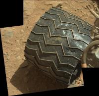
One of the wheels on Sol 486.
Jan van Driel
|
|
|
|
|
|
|
Dec 21 2013, 02:43 AM
Post
#100
|
|
|
Member Group: Members Posts: 866 Joined: 15-March 05 From: Santa Cruz, CA Member No.: 196 |
little punched-out shred in SOL488 image and the adjacent one as well, seems to have been pushed in quite far. soon as it falls off were doomed!!
 the inside surface is rendering with some pretty convincing displacement mapping now. |
|
|
|
|
Dec 21 2013, 06:03 PM
Post
#101
|
|
|
Member Group: Members Posts: 124 Joined: 20-April 05 Member No.: 291 |
Seems a bit of the wear worry is striking a chord with the team as well. While none of the dents and dings are serious, it apparently is more than they were expecting this far in. From the link above:
QUOTE "We want to take a full inventory of the condition of the wheels," Erickson said. "Dents and holes were anticipated, but the amount of wear appears to have accelerated in the past month or so. It appears to be correlated with driving over rougher terrain. The wheels can sustain significant damage without impairing the rover's ability to drive. However, we would like to understand the impact that this terrain type has on the wheels, to help with planning future drives."
|
|
|
|
|
Dec 21 2013, 10:40 PM
Post
#102
|
|
 Administrator Group: Admin Posts: 5172 Joined: 4-August 05 From: Pasadena, CA, USA, Earth Member No.: 454 |
Yeah, and any pause to inspect the wheels is clearly at least briefly harmful to the goal of getting to Mt. Sharp as soon as possible, but hopefully in the grand scheme of things it is a miniscule one, so I'm not going to change my subtitle for this thread....yet.
I was thinking about how to harness the powers of this forum for good when it comes to the wheels. One question I often have when I see wheel photos is: are those new holes? Or are they old holes? If they are old, are they bigger than they used to be? I made myself a map of the wheels and was thinking about trying to note precisely where and when specific tears and holes were first noticed, hoping to use it to check subsequent wheel images to see if holes are new ones or old ones but it's a bigger job than I have time for. Maybe the attached PDF/PNG map of the wheels would be of some use to people...? 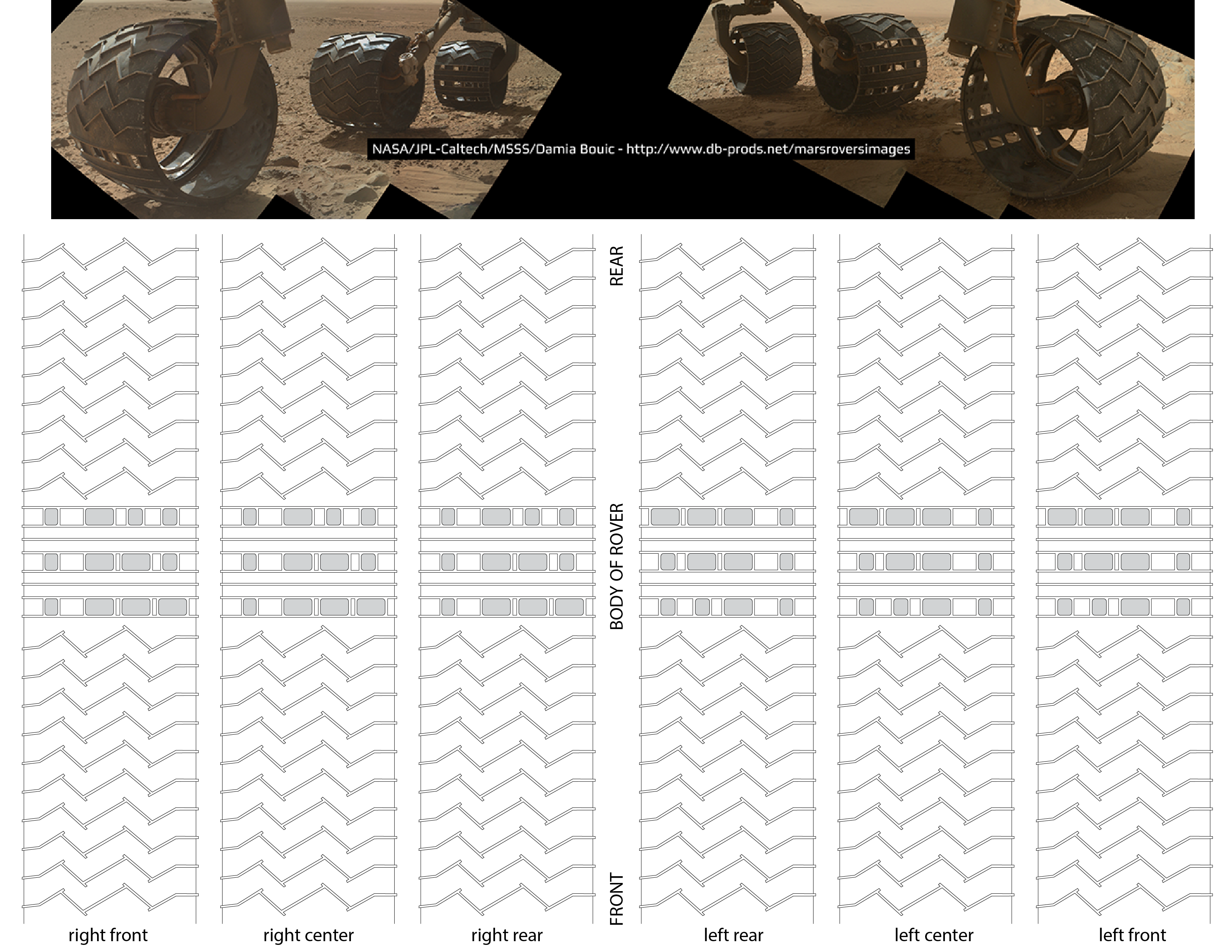  wheel_tread_map.pdf ( 1.53MB )
Number of downloads: 1024
wheel_tread_map.pdf ( 1.53MB )
Number of downloads: 1024-------------------- My website - My Patreon - @elakdawalla on Twitter - Please support unmannedspaceflight.com by donating here.
|
|
|
|
|
Dec 22 2013, 12:04 AM
Post
#103
|
|
|
Senior Member Group: Members Posts: 2082 Joined: 13-February 10 From: Ontario Member No.: 5221 |
If they are concerned enough to be thinking about route changes, as Erickson is implying, what would that mean? Sticking closer to sandy, rock-free ground? The obvious place to go in that case is the dune field itself, but then there's concerns about getting stuck, and of course missing waypoint 4. Trade-offs, trade-offs, and more trade-offs...
|
|
|
|
|
Dec 22 2013, 02:14 AM
Post
#104
|
|
|
Senior Member Group: Members Posts: 4246 Joined: 17-January 05 Member No.: 152 |
QUOTE (elakdawalla @ Dec 21 2013, 10:40 PM) I made myself a map of the wheels Here's an idea for an image wizard: transform the MH/mastcam/navcam images of the wheels into a strip map like what Emily's posted. Basically "unwrap" the images to a rectangular strip, or portion thereof. I remember that someone did basically the same thing with images of a drill hole some time ago. |
|
|
|
|
Dec 22 2013, 02:29 AM
Post
#105
|
||
|
Senior Member Group: Members Posts: 2346 Joined: 7-December 12 Member No.: 6780 |
I think, it has been Zelenyikot, not quite sure.
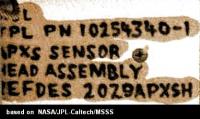
In the short run, I just can provide as an example, that the idea works with the APXS inscription:
Raw image. |
|
|
|
|
|
|

|
Lo-Fi Version | Time is now: 27th April 2024 - 09:03 PM |
|
RULES AND GUIDELINES Please read the Forum Rules and Guidelines before posting. IMAGE COPYRIGHT |
OPINIONS AND MODERATION Opinions expressed on UnmannedSpaceflight.com are those of the individual posters and do not necessarily reflect the opinions of UnmannedSpaceflight.com or The Planetary Society. The all-volunteer UnmannedSpaceflight.com moderation team is wholly independent of The Planetary Society. The Planetary Society has no influence over decisions made by the UnmannedSpaceflight.com moderators. |
SUPPORT THE FORUM Unmannedspaceflight.com is funded by the Planetary Society. Please consider supporting our work and many other projects by donating to the Society or becoming a member. |
|