Juno PDS data |

  |
Juno PDS data |
 Jun 6 2018, 12:35 AM Jun 6 2018, 12:35 AM
Post
#106
|
||
 IMG to PNG GOD  Group: Moderator Posts: 2250 Joined: 19-February 04 From: Near fire and ice Member No.: 38 |
I'm currently making a few improvements to my JunoCam-related software and now have some questions for Mike (Gerald might also be familiar with this).
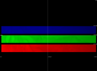
Yesterday I noticed that recently a very interesting correction was made to how the USGS ISIS3 software handles JunoCam images. This was interesting to me because having processed a lot of JunoCam images I have gradually started to suspect there still was a small, systematic geometric error in my processing pipeline. In particular the (small) correction I have to apply to the camera pointing is almost always negative in the sample direction in image coordinates - this is highly suspicious. Also I usually have to modify the START_TIME (only adding 0.06188 and modifying INTERFRAME_DELAY usually isn't quite accurate enough). But now I see from the most recent ISIS3 files (in particular the junoAddendum005.ti file located in the iak directory where ISIS3 stores the JunoCam SPICE kernels) that the B/G/R framelet offsets from the top of the 1648x1200 frame are 441.52, 596.52 and 751.52, respectively. Before this recent correction ISIS3 used the values 456, 611 and 766, respectively. Interestingly these are also the values I have been using in my software until now. To make absolutely sure I now have everything correct, below is an image showing the locations of the framelets within a single 1648x1200 pixel image as the image would appear if I wanted to handle this as if the image was from a regular framing camera:
Is the above image correct? (in particular the exact vertical position of the B/G/R framelets). [EDIT June 9, 2018: The image turned out to be incorrect, the vertical position of the framlets isn't correct] Another question to make sure I understand everything correctly - this is also based on numbers from the above mentioned junoAddendum005.ti file. Assuming Juno always has perfect pointing and you command the spacecraft to point JunoCam (or more accurately, JunoCam's optical axis) at a star, would the star be at pixel (814.21, 600) in the resulting image? Normally you would expect the star to be at (824, 600) (i.e. x=number of pixels in the sample direction divided by 2) but these images have dummy pixels etc. at the image edges. The source of the above confusion regarding the filter offsets is probably this diagram from the juno_junocam_v02.ti kernel: CODE --- 0,0--------------------------------------------. 4.94 deg | METHANE 128 pix * | -------- --- `-----------------------------------------1648,128 | 245 pixels | --- 0,0--------------------------------------------. | 4.94 deg | BLUE 128 pix * | | --- --- `-----------------------------------------1648,128 | |80 pixels +Zjc x-------------> +Xjc --- --- --- 0,0---------------------|----------------------. | |75 pixels 4.94 deg | GREEN 128 pix * | | --- --- `----------------------|------------------1648,128 | | | --- 0,0---------------------|----------------------. | 230 pixels 4.94 deg | RED 128 pix * | -------- --- `----------------------|------------------1648,128 | V +Yjc I interpreted this to mean that the filter offsets relative to the top of the 1648x1200 pixel frame were 456, 611 and 766 and apparently the ISIS3 software also did this until it was corrected last month. Either the diagram above is very easy to misunderstand or it is incorrect (I suspect the latter). |
|
 |
 
|
|
|
Jun 6 2018, 12:50 AM
Post
#107
|
|
|
Senior Member Group: Members Posts: 2511 Joined: 13-September 05 Member No.: 497 |
QUOTE (Bjorn Jonsson @ Jun 5 2018, 04:35 PM)  Either the diagram above is very easy to misunderstand or it is incorrect (I suspect the latter). I suggested that that diagram be removed completely as I found it more confusing than helpful; I'm actually not sure if it's wrong or just incomplete. At any rate, you're supposed to be using the values in INS-6150*_DISTORTION_Y. I tried to be as clear and specific as I could be in the comments and pseudocode in the "optical distortion" section. I can't immediately map what I said there to numbers like 441.52; since we don't read out, much less transmit, the entire frame, I don't spend a lot of time thinking about what the coordinates of the entire frame are any more. I hope that helped. Sorry for any confusion. If you find some ambiguity in the "optical distortion" section that you would like resolved, let me know. -------------------- Disclaimer: This post is based on public information only. Any opinions are my own.
|
|
|
|
|
Jun 6 2018, 05:51 AM
Post
#108
|
|
|
Senior Member Group: Members Posts: 2346 Joined: 7-December 12 Member No.: 6780 |
QUOTE (Bjorn Jonsson @ Jun 6 2018, 02:35 AM) But now I see from the most recent ISIS3 files (in particular the junoAddendum005.ti file located in the iak directory where ISIS3 stores the JunoCam SPICE kernels) that the B/G/R framelet offsets from the top of the 1648x1200 frame are 441.52, 596.52 and 751.52, respectively. Before this recent correction ISIS3 used the values 456, 611 and 766, respectively. Interestingly these are also the values I have been using in my software until now. What really counts are the relative values. As long as the relative y-offsets (155) are the same, you can either adjust the y-position of the optical axis, or the absolute values of the readout region. I'm prefering to leave the absolute pixel positions as they have been, and adjust the optical axis, instead. But I'd call this as matter of taste. |
|
|
|
|
Jun 6 2018, 06:09 AM
Post
#109
|
|
|
Senior Member Group: Members Posts: 2511 Joined: 13-September 05 Member No.: 497 |
QUOTE (Gerald @ Jun 5 2018, 09:51 PM) What really counts are the relative values. I'm not 100% sure what you mean by this. If you use the recipe I describe then you can just use the tabulated DISTORTION_Y values in the kernel and they account for both the readout offsets and the optic axis in one step. If you don't follow my recipe, then you're on your own for figuring out how those are combined: which is more work, no advantage I can see, and more potential error sources. -------------------- Disclaimer: This post is based on public information only. Any opinions are my own.
|
|
|
|
|
Jun 6 2018, 07:52 AM
Post
#110
|
|
|
Member Group: Members Posts: 406 Joined: 18-September 17 Member No.: 8250 |
I'll speculate the value changes were to fix their implementation of Mike's lens correction.
Subtracting their new offset values from CCD mid-line yields the juno_junocam_v02.ti INS-6150?_DISTORTION_Y values. 600-284.52=315.48 600-441.52=158.48 600-596.52=3.48 600-751.52=-151.52 FWIW, my pipeline converts framelets back to full frames using 456, 611, 766 as the readout positions prior applying the lens correction. I didn't see these "Addendum Kernel" files under source control on GitHub, and only found them after doing a partial data install with: rsync -azv --delete --partial --exclude='kernels/ck' isisdist.astrogeology.usgs.gov::isis3data/data/juno data/ I didn't see an Issue directly related to this change at https://isis.astrogeology.usgs.gov/fixit/issues?set_filter=1 But maybe they discovered the problem while investigating and fixing their most recent JunoCam Issue https://isis.astrogeology.usgs.gov/fixit/issues/5236 |
|
|
|
|
Jun 6 2018, 10:01 AM
Post
#111
|
|
|
Senior Member Group: Members Posts: 2346 Joined: 7-December 12 Member No.: 6780 |
QUOTE (mcaplinger @ Jun 6 2018, 08:09 AM) I'm not 100% sure what you mean by this... When you are just using the kernel for processing, it doesn't make a difference. When you are calibrating the optics, it's an advantage to know the relative positions of the readout regions being reliable constants that don't require a calibration, except maybe determining some chromatic aberration. Those relative positions are only implicitely provided by the DISTORTION_Y values. So, the description of the CCD layout is helpful. The settings could be different for a 3-CCD camera with a possibly individual distortion to be determined for each CCD separately. |
|
|
|
|
Jun 7 2018, 12:10 AM
Post
#112
|
|
|
IMG to PNG GOD Group: Moderator Posts: 2250 Joined: 19-February 04 From: Near fire and ice Member No.: 38 |
QUOTE (Brian Swift @ Jun 6 2018, 07:52 AM) But maybe they discovered the problem while investigating and fixing their most recent JunoCam Issue https://isis.astrogeology.usgs.gov/fixit/issues/5236 Yes, that's the one. See #6 there ("...Correcting this has also shown that our filter positions on the ccd are incorrect."). QUOTE (Brian Swift @ Jun 6 2018, 07:52 AM) I didn't see these "Addendum Kernel" files under source control on GitHub, and only found them after doing a partial data install with: rsync -azv --delete --partial --exclude='kernels/ck' isisdist.astrogeology.usgs.gov::isis3data/data/juno data/ That's also how I got them. Both the new version of the kernel (junoAddendum005.ti) and the previous version (junoAddendum004.ti) contain this near the top: INS-61500_BORESIGHT_LINE = 600 INS-61500_BORESIGHT_SAMPLE = 814.21 However, further down there is an important difference. The new version (junoAddendum005.ti) contains this (I have added the value from the previous version in parentheses): INS-61504_FILTER_NAME = 'METHANE' INS-61504_FILTER_OFFSET = 284.52 (291) INS-61504_FILTER_LINES = 128 INS-61504_FILTER_SAMPLES = 1648 INS-61501_FILTER_NAME = 'BLUE' INS-61501_FILTER_OFFSET = 441.52 (456) INS-61501_FILTER_LINES = 128 INS-61501_FILTER_SAMPLES = 1648 INS-61502_FILTER_NAME = 'GREEN' INS-61502_FILTER_OFFSET = 596.52 (611) INS-61502_FILTER_LINES = 128 INS-61502_FILTER_SAMPLES = 1648 INS-61503_FILTER_NAME = 'RED' INS-61503_FILTER_OFFSET = 751.52 (766) INS-61503_FILTER_LINES = 128 INS-61503_FILTER_SAMPLES = 1648 It's because of this that I *think* the reconstructed full frame that I posted yesterday is correct. The optical axis is at y=600 and the new numbers above are consistent with Mike's code if I understand everything correctly. BTW the reason I want to reconstruct the full frame as in the image in my above post is that once I've done that I can proceed as if each set of B/G/R framelets is an image from a regular 1648x1200 pixel framing camera. JunoCam is then no longer a special case and I can use more or less the same processing pipeline I'm using for e.g. Cassini and Voyager images when reprojecting the framelets to simple cylindrical projection (with the addition of automatically mosaicking everything in the end to get one map containing data from all of the framelets). QUOTE (Brian Swift @ Jun 6 2018, 07:52 AM) FWIW, my pipeline converts framelets back to full frames using 456, 611, 766 as the readout positions prior applying the lens correction. That's also what I have been doing until now. But now I suspect this is incorrect, see e.g. the data above from junoAddendum005.ti. I'll probably do some experiments soon to see what seems to work best but I'm still slightly confused (hopefully I can finish figuring this out this weekend). It was to make absolutely sure I understand everything correctly that I included this elementary question in my post yesterday: QUOTE (Bjorn Jonsson @ Jun 6 2018, 12:35 AM) Assuming Juno always has perfect pointing and you command the spacecraft to point JunoCam (or more accurately, JunoCam's optical axis) at a star, would the star be at pixel (814.21, 600) in the resulting image? Normally you would expect the star to be at (824, 600) (i.e. x=number of pixels in the sample direction divided by 2) but these images have dummy pixels etc. at the image edges. The value 814.21 mentioned here is in the junoAddendum005.ti file (INS-61500_BORESIGHT_SAMPLE) and also in the juno_junocam_v02.ti kernel (INS-6150#_DISTORTION_X). I should add that it was when I started processing the JIRAM data back in January that I started to suspect really strongly that something wasn't quite correct in my JunoCam processing pipeline. In the JIRAM images, the position of Jupiter's limb (or disc in global views) always matched (or very nearly matched) what I computed from the kernels. |
|
|
|
|
Jun 7 2018, 05:57 AM
Post
#113
|
|
|
Senior Member Group: Members Posts: 2511 Joined: 13-September 05 Member No.: 497 |
QUOTE (Bjorn Jonsson @ Jun 5 2018, 04:35 PM) would the star be at pixel (814.21, 600) in the resulting image? The 814.21 is the pixel coordinate given the 1648-wide image, so any issues about dummy pixels have already been accounted for. I've got no idea what USGS is doing with the 600. The optic axis isn't at a Y of 600 any more than it's at an X of 1648/2. I wrote the code in the kernel file so there would be no ambiguity about what needed to be done with managing the framelets. This code has been validated with limb fitting in one direction and ray tracing in the other so I'm pretty confident it's right to a pixel or two. If you want to use a different formalism, that's fine, but don't expect me to debug it -- I had enough trouble with my recommended method. -------------------- Disclaimer: This post is based on public information only. Any opinions are my own.
|
|
|
|
|
Jun 7 2018, 07:00 AM
Post
#114
|
|
|
Member Group: Members Posts: 406 Joined: 18-September 17 Member No.: 8250 |
QUOTE (Bjorn Jonsson @ Jun 6 2018, 05:10 PM) Yes, that's the one. See #6 there ("...Correcting this has also shown that our filter positions on the ccd are incorrect."). Yup, missed that. Note, (as Mike mentioned) the DISTORTION_Y values used by the "code recipe" in juno_junocam_v02.ti bake together the readout offsets with the "optical axis". These can be un-baked as follows: 600+78.48-158.48-64=456.00 600+78.48-3.48-64=611.00 600+78.48-(-151.52)-64=766.00 (600 == ccd center Y, and 64 == half a framelet) Since my pipeline doesn't attempt to hit specific targets, I haven't been concerned with boresight and just allow it to be the CCD center. I'll admit I hadn't realized until this current review of the recipe that DISTORTION_ parameters were specifying the boresight. I'd assumed they were only specifying the "principal point" offsets to the Brown distortion model, and that the boresight would be at CCD center. Mike: While it shouldn't effect image processing (since it isn't associated with a filter), do you think the value of INS-61500_DISTORTION_Y (optical axis relative to full frame) value should be 678.48 instead of 78.48? |
|
|
|
|
Jun 7 2018, 11:12 AM
Post
#115
|
|
|
Senior Member Group: Members Posts: 2346 Joined: 7-December 12 Member No.: 6780 |
Somehow, I get the feeling, that with almost each post another frame of reference is introduced implicitely, and mixed with the frames already mentioned before.
So, a first step to define what everyone is talking about would be an unambiguous definition of the frame(s) of reference you are refering to. I'm usually working with the two frames of reference that define either the lower left, or the upper left pixel of the CCD as (0;0), and that are using the horizontal offset between two consecutive pixels as the unit of length. Other translational options that seem to be discussed here are defining pixel row 600 as 0 for y, but column 0 as 0 for x, or different from that, defining y=600 as the y-position of the optical axis, both with two y-flipped versions. So, just discussing constants without sufficient context regarding the applied frame of reference will always result in confusion. The rotation matrix of the camera frame with respect to the Juno frame is yet another question, as well as Juno's rotation axis with repect to the Juno frame, and handled outside JunoCam's instrument kernel. I'm going to analyse JunoCam's geometry during the next three months, hopefully to subpixel accuracy, but hesitate to discuss the lots of dead-ends. Especially, I'll review whether the Brownian distortion model is applicable to JunoCam at all on this level of accuracy, and develop and check a set of alternative families of geometrical distortion models. I'm planning to discuss this on EPSC in September as a part of a talk. But I don't intend to release much intermediate material before, except the according EPSC abstract. If the investigation will result in any new insight, I may consider to write an according peer-reviewed paper, and in this case of course provide data for a refined instrument kernel. |
|
|
|
|
Jun 7 2018, 03:20 PM
Post
#116
|
|
|
Senior Member Group: Members Posts: 2511 Joined: 13-September 05 Member No.: 497 |
QUOTE (Brian Swift @ Jun 6 2018, 11:00 PM) do you think the value of INS-61500_DISTORTION_Y (optical axis relative to full frame) value should be 678.48 instead of 78.48? The code doesn't use this value, I didn't put it in the kernel, and I don't know what it's supposed to mean. You could very well be right technically (since for brevity I folded the typical height/2 offset into the constants themselves as Gerald points out.) In a perfect world, these keywords would have well-defined and documented meanings, and the SPICE toolkit would have functions that used them and performed the basic camera geometry functions. As it is, the toolkit doesn't have those functions and the keywords don't have well-defined meanings, leaving us to do the best we can in the comments. The comments were written after a big effort to determine the best possible fit from in-flight data and in the face of massive confusion from practically everyone who had ever written code to deal with pushframe systems about how to manage Junocam data. So my attitude was very much "do this specific thing" instead of "here's a whole bunch of information that will allow you to make your own design choices and mistakes and then come back to me and complain about it."  -------------------- Disclaimer: This post is based on public information only. Any opinions are my own.
|
|
|
|
|
Jun 7 2018, 08:01 PM
Post
#117
|
|
 Member Group: Members Posts: 334 Joined: 11-December 12 From: The home of Corby Crater (Corby-England) Member No.: 6783 |
Mr Caplinger, you are a living legend, brilliant!
|
|
|
|
|
Jun 7 2018, 09:21 PM
Post
#118
|
|
|
Member Group: Members Posts: 406 Joined: 18-September 17 Member No.: 8250 |
QUOTE (Gerald @ Jun 7 2018, 04:12 AM) I'm going to analyse JunoCam's geometry during the next three months, hopefully to subpixel accuracy, but hesitate to discuss the lots of dead-ends. Especially, I'll review whether the Brownian distortion model is applicable to JunoCam at all on this level of accuracy, ... The results in my 4/10/2018 posting in this thread demonstrate subpixel correction from a Brown-Conrady model using only K1,K2,P1,P2 parameters. I found a similar level of correction from a model consisting of Brown-Conrady K1,K2 with two additional parameters for chromatic aberration. I stuck with K1,K2,P1,P2 for my pipeline based only a preference for a single correction function, rather than three based on color. I think getting to deci-pixel or centi-pixel alignment, or untangling non-radial geometric corrections from CA from timing slop, would certainly be an advancement. If I were to revisit my modeling, Id change the process I use for generation of control points. Currently intensity centroids are derived from images that have been flattened for detecting point sources. Id change this to only use the flattened images for detection and coarse location identification, and then produce the intensity centroids from the corresponding locations in the unflattened images. I look forward to your results. |
|
|
|
|
Jun 7 2018, 09:52 PM
Post
#119
|
|
|
IMG to PNG GOD Group: Moderator Posts: 2250 Joined: 19-February 04 From: Near fire and ice Member No.: 38 |
QUOTE (mcaplinger @ Jun 7 2018, 03:20 PM) The comments were written after a big effort to determine the best possible fit from in-flight data and in the face of massive confusion from practically everyone who had ever written code to deal with pushframe systems about how to manage Junocam data. So my attitude was very much "do this specific thing" instead of "here's a whole bunch of information that will allow you to make your own design choices and mistakes and then come back to me and complain about it." Well, that might be me  (among others). In hindsight maybe I should have rewritten most of my code from scratch. What happened though is that I had largely finished writing it back in 2013 around the time of the Earth flyby (at that time less information was available). I then modified/corrected it in the months following JOI when more information was available. Big thanks for taking the time to post various useful information here and for answering various JunoCam-related questions. (among others). In hindsight maybe I should have rewritten most of my code from scratch. What happened though is that I had largely finished writing it back in 2013 around the time of the Earth flyby (at that time less information was available). I then modified/corrected it in the months following JOI when more information was available. Big thanks for taking the time to post various useful information here and for answering various JunoCam-related questions.And the bug/small systematic error I've been dealing with is now finally gone (and a lot of my confusion too), see below: QUOTE (mcaplinger @ Jun 7 2018, 05:57 AM) QUOTE (Bjorn Jonsson @ Jun 5 2018, 04:35 PM) would the star be at pixel (814.21, 600) in the resulting image? The 814.21 is the pixel coordinate given the 1648-wide image, so any issues about dummy pixels have already been accounted for.That's it!! It turns out that the main problem was that I was using an incorrect value here. Having done a few quick tests it's clear that the small systematic error is now gone and the limb fit errors I get have dropped to a maximum of 2-3 pixels (0-1 is common but determining the exact value is often difficult due to haze at the limb). QUOTE (mcaplinger @ Jun 7 2018, 05:57 AM) I've got no idea what USGS is doing with the 600. The optic axis isn't at a Y of 600 any more than it's at an X of 1648/2. I've got no idea either. But it's now clear that the recent changes to ISIS3 (or the ISIS3-specific kernels) are of no relevance to me. The correct framelet offsets (from the top) are 456, 611 and 766 pixels as I've been using. But the diagram in the IK file is confusing as has been mentioned. In particular the numbers in the diagram are of no direct relevance to your code in the IK file but this isn't explicitly mentioned. Perhaps it would be best to remove the diagram as you suggested (or at least change it). QUOTE (Gerald @ Jun 7 2018, 11:12 AM) I'm going to analyse JunoCam's geometry during the next three months, hopefully to subpixel accuracy, but hesitate to discuss the lots of dead-ends. Especially, I'll review whether the Brownian distortion model is applicable to JunoCam at all on this level of accuracy, and develop and check a set of alternative families of geometrical distortion models. I'm planning to discuss this on EPSC in September as a part of a talk. But I don't intend to release much intermediate material before, except the according EPSC abstract. If the investigation will result in any new insight, I may consider to write an according peer-reviewed paper, and in this case of course provide data for a refined instrument kernel. This is very interesting and I look forward to seeing the results even though distortion isn't a big problem in my case. If color channel misalignment becomes too noticeable I simply warp the G/B channels into the red channel. The misalignment isn't big (can be ~2 pixels near the image edges) but still noticeable in high contrast areas in enhanced images. |
|
|
|
|
Jun 7 2018, 11:42 PM
Post
#120
|
|
|
Senior Member Group: Members Posts: 2346 Joined: 7-December 12 Member No.: 6780 |
I'm trying to analyse Jupiter's cloud velocity field, where displacements of features between images reprojected to common vantage points are often less than a raw pixel. So, with global geometrical uncertainties, I need to apply global corrections that remove information I'd liked to retrieve. In order to resolve this, not just color channel alignment, but also absolute alignment with Jupiter's shape model should be no more than 1/10 raw pixel. Manually, I can adjust to a fraction of a pixel, but that's rather time consuming, and still less accurate and reliable than it should be for this purpose.
Any of my attempts to define a globally accurate lense distortion model on the basis of Brown-Conrady with only 4 free parameters failed thus far. Locally it's no problem to go below 1/100 pixel accuracy with respect to some error metrics. But I would have been surprised, if Brown-Conrady would have worked so easily for global lense geometry. With an increasing number of non-zero parameters, the Brown-Conrady model becomes more and more unstable and unrealistic. That issue is well-known since several decades, at least, (probably more than a century in some cases) for other approximations derived from Taylor polynomials. (Think, e.g. of splines of polynomials of degree 7 rather than cubic splines. They oscillate too much to be useful in practice.) Therefore, I'll consider approaches rather different from Brown-Conrady. But I can't tell which of the long list of those more or less straightforward alternatives will be as successful as required, before it's elaborated and tested. Those methods have their own specific issues. Another point that might turn out to be relevant is Jupiter's deviation from its idealized IAU shape model. I might eventually ask the Juno gravity group for numbers, or do the math myself. |
|
|
|
|

|
Lo-Fi Version | Time is now: 29th April 2024 - 03:31 AM |
|
RULES AND GUIDELINES Please read the Forum Rules and Guidelines before posting. IMAGE COPYRIGHT |
OPINIONS AND MODERATION Opinions expressed on UnmannedSpaceflight.com are those of the individual posters and do not necessarily reflect the opinions of UnmannedSpaceflight.com or The Planetary Society. The all-volunteer UnmannedSpaceflight.com moderation team is wholly independent of The Planetary Society. The Planetary Society has no influence over decisions made by the UnmannedSpaceflight.com moderators. |
SUPPORT THE FORUM Unmannedspaceflight.com is funded by the Planetary Society. Please consider supporting our work and many other projects by donating to the Society or becoming a member. |
|