Juno PDS data |

  |
Juno PDS data |
 Feb 6 2019, 01:38 AM Feb 6 2019, 01:38 AM
Post
#151
|
||
|
Member  Group: Members Posts: 890 Joined: 18-November 08 Member No.: 4489 |
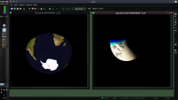
isis3 remaps images - there is no back to camera mapping (map2cam) for juno images
the Earth fly by image "JNCE_2013282_00C00102_V01"
--- edit --- for some unknown reason the jpg's of the tiff images are not uploading -- so on to imagebox Simple cylindrical ( color is over saturated )  ortho( color is over saturated ) 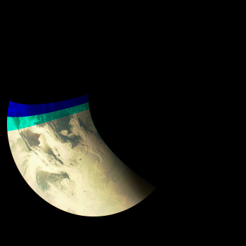 BlueMarble -- in the same ortho projection for comparison 
|
|
 |
 
|
|
|
Feb 6 2019, 05:12 AM
Post
#152
|
|
|
Member Group: Members Posts: 406 Joined: 18-September 17 Member No.: 8250 |
QUOTE (JohnVV @ Feb 5 2019, 05:38 PM)  ... ortho( color is over saturated ) Thanks for posting these, they answered my question. |
|
|
|
|
Feb 6 2019, 11:28 PM
Post
#153
|
||
|
Senior Member Group: Members Posts: 2511 Joined: 13-September 05 Member No.: 497 |
QUOTE (Brian Swift @ Feb 4 2019, 11:00 PM) I believe the Junocam visible limb is at a higher elevation than the 1-bar limb returned by SPICE. The image below shows per-channel overlays of the limbs of Io and Jupiter as predicted by our best current model for PJ16-011, no timing adjustment other than our nominal recommended one. The Io limb is pretty close to dead on (maybe a pixel off in the red) and the Jupiter limb is clearly low relative to the observed limb by 4 pixels or so. So that does support the idea that what we see is higher than the limb defined by the IAU radii in the SPICE planetary constants file. Of course, the observed limb is not super-sharp so it's a judgement call about where it is exactly.
-------------------- Disclaimer: This post is based on public information only. Any opinions are my own.
|
|
|
|
|
|
|
Feb 12 2019, 04:06 PM
Post
#154
|
|
 Senior Member Group: Moderator Posts: 3232 Joined: 11-February 04 From: Tucson, AZ Member No.: 23 |
Juno data (including JunoCAM but excluding JIRAM) for PJ13 and PJ14 is now in the PDS:
https://pds.nasa.gov/datasearch/subscriptio...-20190211.shtml -------------------- &@^^!% Jim! I'm a geologist, not a physicist!
The Gish Bar Times - A Blog all about Jupiter's Moon Io |
|
|
|
|
Feb 13 2019, 12:39 AM
Post
#155
|
||
 IMG to PNG GOD Group: Moderator Posts: 2250 Joined: 19-February 04 From: Near fire and ice Member No.: 38 |
QUOTE (Brian Swift @ Feb 5 2019, 07:00 AM) QUOTE (Bjorn Jonsson @ Oct 13 2018, 12:53 PM) This is exactly what I've been doing. Following this I also do limb fitting of the last image containing the limb and then adjust the interframe delay slightly if necessary (I typically end up with values like 0.3711 or 0.3708 or something like that instead of 0.371). ... As a 'sanity check' it would be interesting to know which START_TIME value you got for an image or two, especially for images obtained at an altitude of ~25,000 km or closer. Instead of limb fitting for start time and inter frame delay, have you considered fitting for start time and planet radius? I believe the Junocam visible limb is at a higher elevation than the 1-bar limb returned by SPICE. For example, in the occultation of Io in PJ16_11, SPICE (Web GeoGalc) predicts a start time of 2018-10-29T20:50:43.855 which is almost a second later than the image time of frame 8, 20:50:42.932. However, the image shows the visible limb already covering about 1/3 of Io. I briefly considered fitting for the planet radius but decided not to for several reasons. The biggest reason is that I suspect the cloud altitudes vary depending on cloud 'type' (light or dark). In particular the bright, white ammonia clouds should usually be at a higher altitude than the darker clouds. In other words, if this correct Jupiter's shape is slightly 'irregular' if you define Jupiter's radius by the top of the visible clouds and not by a specific pressure level. I think I may have seen tentative evidence of variable cloud altitudes at the limb in some images but I'm not completely sure yet and need to look further into this. Another possible source of errors is that a reconstructed SPK kernel doesn't become available until several weeks after a a flyby. I have yet to compare the reconstructed SPK kernels to the predict kernels that become available immediately. QUOTE (Brian Swift @ Feb 5 2019, 07:00 AM) I've only done a few fits since my process isn't fully automated yet, but here are some preliminary results: Radius increase (km), start time adjustment, image id, frame numbers used for fit, filter 95 -.013 PJ14_19 7,31 green 47 -.004 PJ14_25 13,29 green 45 -.004 PJ14_25 7,35 green 90 .0015 PJ16_11 7,31 red 95 .0020 PJ16_11 8,33 green 90 .0005 PJ16_11 12,33 blue I have no reason to expect the height variation to be uniform across Jupiter, and can think of enough potential effects on it to eliminate any desire on my part to attempt to model it. This is very interesting and I'll probably do some processing runs to see if I get similar results (I hadn't processed these exact images yet). I'm especially interested in the start time adjustment. QUOTE (Gerald @ Feb 5 2019, 02:42 PM) We don't know the exact pressure of the level of the cloud tops. And also the cloud tops are probably not at the same pressure level everywhere - see above. QUOTE (mcaplinger @ Feb 6 2019, 11:28 PM) The image below shows per-channel overlays of the limbs of Io and Jupiter as predicted by our best current model for PJ16-011, no timing adjustment other than our nominal recommended one. The Io limb is pretty close to dead on (maybe a pixel off in the red) and the Jupiter limb is clearly low relative to the observed limb by 4 pixels or so. So that does support the idea that what we see is higher than the limb defined by the IAU radii in the SPICE planetary constants file. Of course, the observed limb is not super-sharp so it's a judgement call about where it is exactly.
Big thanks for posting these, I've been wanting to see something like this for some time. Typically, the errors I'm getting at Jupiter's limb are similar to this when I adjust the start time using the recommended values but the fuzziness of the limb often complicates matters and makes it difficult to locate the cloud tops. |
|
|
|
|
|
|
Feb 13 2019, 07:40 AM
Post
#156
|
|
|
Member Group: Members Posts: 406 Joined: 18-September 17 Member No.: 8250 |
QUOTE (Bjorn Jonsson @ Feb 12 2019, 04:39 PM) Another possible source of errors is that a reconstructed SPK kernel doesn't become available until several weeks after a a flyby. I have yet to compare the reconstructed SPK kernels to the predict kernels that become available immediately. I believe there was a change of about 8ms on PJ16_11 (Scratched my head for bit trying to figure out why I wasn't getting the same result I had produced earlier, and eventually realized I'd update the SPK at some point). FWIW, in my matching code I gradient filter the image and define the limb as the maximal gradient. QUOTE This is very interesting and I'll probably do some processing runs to see if I get similar results (I hadn't processed these exact images yet). I'm especially interested in the start time adjustment. The start times could all easily be off by a constant since my model uses its own spacecraft to camera frame transform matrix. (I haven't checked to see how much z-rotation difference there is between mine and the standard matrix). |
|
|
|
|
Feb 23 2019, 08:00 AM
Post
#157
|
|
|
Member Group: Members Posts: 406 Joined: 18-September 17 Member No.: 8250 |
Update to Juno3D pushed to https://github.com/BrianSwift/JunoCam/tree/master/Juno3D
|
|
|
|
|
Mar 11 2019, 04:32 PM
Post
#158
|
|
|
Member Group: Members Posts: 406 Joined: 18-September 17 Member No.: 8250 |
Mike, I just noticed that prior to PJ10 TDI=1 was rare (TDI=2/3 typical), but from PJ10 forward TDI=1 seems to be the default.
I'm just curious, can you comment on the motivation for the change? |
|
|
|
|
Mar 11 2019, 05:53 PM
Post
#159
|
|
|
Senior Member Group: Members Posts: 2511 Joined: 13-September 05 Member No.: 497 |
QUOTE (Brian Swift @ Mar 11 2019, 08:32 AM) can you comment on the motivation for the change? Higher signal levels due to the evolving sun angle. We are still using high TDI for some of the polar images in an effort to see the circumpolar cyclones better. -------------------- Disclaimer: This post is based on public information only. Any opinions are my own.
|
|
|
|
|
Feb 5 2020, 05:51 PM
Post
#160
|
|
|
Member Group: Members Posts: 406 Joined: 18-September 17 Member No.: 8250 |
Mike, can you describe the Map Projection used for images that accompany the raw data images on the missionjuno site,
or point me to and existing description. |
|
|
|
|
Feb 5 2020, 09:41 PM
Post
#161
|
|
|
Senior Member Group: Members Posts: 2511 Joined: 13-September 05 Member No.: 497 |
QUOTE (Brian Swift @ Feb 5 2020, 09:51 AM) Mike, can you describe the Map Projection used for images that accompany the raw data images on the missionjuno site... It is an uncontrolled point perspective projection only intended as an unofficial pretty picture and not archived with PDS. -------------------- Disclaimer: This post is based on public information only. Any opinions are my own.
|
|
|
|
|
Mar 29 2020, 12:14 AM
Post
#162
|
|
|
IMG to PNG GOD Group: Moderator Posts: 2250 Joined: 19-February 04 From: Near fire and ice Member No.: 38 |
At long last I'm adding methane channel processing to my processing pipeline. I'm using image PJ25_19 for testing. My problem is that I am getting large geometric errors but then I remembered discussion of tests where the methane image readout region was changed. I strongly suspect this is the reason for the geometric errors and if I'm correct the IK kernel is incorrect when processing the PJ25 methane images. What is the location of the new readout region, either in absolute pixel coordinates or relative to the readout region before the change?
Has the new/changed readout region been in use after a specific date/perijove or is the 'old' readout region still used in some of the recent images? |
|
|
|
|
Mar 29 2020, 06:54 AM
Post
#163
|
|
|
Senior Member Group: Members Posts: 2511 Joined: 13-September 05 Member No.: 497 |
QUOTE (Bjorn Jonsson @ Mar 28 2020, 04:14 PM) What is the location of the new readout region, either in absolute pixel coordinates or relative to the readout region before the change? For the new readout region, INS-61504_DISTORTION_Y should be 405.48 (the first line of the region changed from 291 to 201.) Inconveniently, we continue to switch back and forth between the two readout regions (we have to use the old methane setting to take RGB data as it happens because the parameters depend on each other). Typically the old one is used on distant images and the new one only on images close to perijove. For PDS products this will be indicated in the comment for each image somehow, but I'm not sure if this information will show up in the missionjuno metadata. Sorry for this confusing state of affairs, we didn't anticipate that we might want to change these parameters at all. -------------------- Disclaimer: This post is based on public information only. Any opinions are my own.
|
|
|
|
|
Jun 2 2021, 05:35 AM
Post
#164
|
|
|
Member Group: Members Posts: 406 Joined: 18-September 17 Member No.: 8250 |
Mike, is the data for the "Junocam relative filter response" table on page 6 of the "Junocam Calibration Report" available anywhere?
Also, can you describe from what locations on the CCD the monochromator values were obtained (and/or share example images)? (considering possible impact of flat field on measured filter response) |
|
|
|
|
Jan 10 2022, 07:32 PM
Post
#165
|
|
|
Member Group: Members Posts: 406 Joined: 18-September 17 Member No.: 8250 |
Has anyone worked with ISIS cubes produced with junocam2isis fullccd=yes?
Does it seem sensible that the produced cubes are single rather than 3-band? |
|
|
|
|

|
Lo-Fi Version | Time is now: 24th April 2024 - 08:20 PM |
|
RULES AND GUIDELINES Please read the Forum Rules and Guidelines before posting. IMAGE COPYRIGHT |
OPINIONS AND MODERATION Opinions expressed on UnmannedSpaceflight.com are those of the individual posters and do not necessarily reflect the opinions of UnmannedSpaceflight.com or The Planetary Society. The all-volunteer UnmannedSpaceflight.com moderation team is wholly independent of The Planetary Society. The Planetary Society has no influence over decisions made by the UnmannedSpaceflight.com moderators. |
SUPPORT THE FORUM Unmannedspaceflight.com is funded by the Planetary Society. Please consider supporting our work and many other projects by donating to the Society or becoming a member. |
|