Enceladus PDS image products |

Enceladus PDS image products |
 Jul 22 2010, 03:22 PM Jul 22 2010, 03:22 PM
Post
#1
|
|||
 IMG to PNG GOD  Group: Moderator Posts: 2251 Joined: 19-February 04 From: Near fire and ice Member No.: 38 |
Following discussions in the Image Processing Techniques subforum (see in particular this thread but also this one) I have now managed to create DEMs of acceptable quality of Enceladus using shape from shading and extensive post processing (mainly destriping). I now have a DEM mosaicked together from 5 images obtained during Cassini's first flyby of Enceladus in 2005. This will eventually become a global 23040x11520 pixel DEM but finishing it is going to be a lot of work (I will probably be using 50-100 images or more). Not all of Enceladus has been imaged at this resolution but there are many high resolution patches and I want a DEM big enough for these.
This 5 image DEM was big enough for me to really want to see what an Enceladus DEM animation would look like. So here we go:  enceladus_sfs_umsf.avi ( 7.74MB )
Number of downloads: 1213
enceladus_sfs_umsf.avi ( 7.74MB )
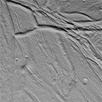
Number of downloads: 1213The field of view is 50 degrees. Most of the animation is at an altitude of 25-30 km. This is similar to Cassini's altitide during the closest flybys and the speed is not far from Cassini's speed either. However, the animation starts and ends at higher altitudes and we also swoop down to an altitude of ~10 km where the resolution of the DEM is highest. This is the Cassini image I used for the highest resolution part of the DEM:
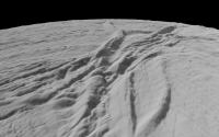
And a single frame from the animation showing a part of this terrain:
The DEM should be fairly accurate - in particular the animation should give a very good general idea of what Enceladus looks like even though some details are inaccurate. Also a higher resolution DEM is really needed for these low altitudes - the surface should look less smooth than it does here. Most of the striping is real though as there are lots of parallel ridges and grooves on Enceladus. There may be some spurious stripes but these are very subtle - the obvious ones are real. I'll do a new animation once I have a significantly bigger DEM. It will probably have better optimized illumination. Shadows are really needed in the first half of this one because I optimized the illumination for the highest resolution part of the DEM. We fly over that part of the DEM at roughly 00:30. EDIT: To play the animation you need to have an H.264 codec installed (if you are using Windows you can find one here for example). |
||
 |
 
|
||
 |
|
Mar 13 2012, 01:01 AM
Post
#61
|
|
|
Junior Member Group: Members Posts: 41 Joined: 12-April 06 Member No.: 738 |
QUOTE (Bjorn Jonsson @ Mar 5 2012, 11:10 PM)  I'm using a slightly modified version of the earliest Hapke function - it's modified to avoid unrealistic effects when the emission angle approaches 90 degrees. The phase effects are interesting and very strong. I even had to reduce the opposition effect a bit to avoid problems with dynamic range. Outstanding video Bjorn! Amazing!  I loved the phase-angle effects too. Could you elaborate on the modified version of the earliest Hapke function or point to where that function can be found? Those zero-phase glares are very prominent on the Moon/lunar surface too, but I suspect generally on any body with rough surfaces. Thank you very much for any pointers! Edit: Is this what you've been working with? -> http://selena.sai.msu.ru/Pug/Publications/ms42/m42_60.pdf Rafael |
|
|
|
|
Mar 17 2012, 12:47 AM
Post
#62
|
|
|
IMG to PNG GOD Group: Moderator Posts: 2251 Joined: 19-February 04 From: Near fire and ice Member No.: 38 |
The modified Hapke function I'm using can be found in my software and (probably) nowhere else ;-). What I'm doing is a crude (probably), simple and empirical modification: I'm preventing the emission angle from ever getting 'too close' to 90 degrees by multiplying it with a number that is a slightly lower than 1 once the emission angle exceeds ~80 degrees. This number is actually a function of the emission angle and gets a bit lower as the emission angle approaches 90 degrees. This may seem strange but since the patch of surface within a pixel really is never perfectly smooth the average emission angle of the visible 'facets' within the pixel should never get extremely close to 90 degrees. This is simpler (but also less accurate) than the more complicated forms of the Hapke functions and eliminates unrealistic bright 'rims' around some terrain edges or planetary discs.
|
|
|
|
|
Mar 17 2012, 01:58 PM
Post
#63
|
|
|
Junior Member Group: Members Posts: 41 Joined: 12-April 06 Member No.: 738 |
Thank you very much Bjorn for the insight!
|
|
|
|
|
Nov 5 2017, 08:10 PM
Post
#64
|
||||||
|
IMG to PNG GOD Group: Moderator Posts: 2251 Joined: 19-February 04 From: Near fire and ice Member No.: 38 |
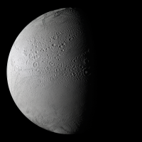
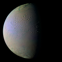
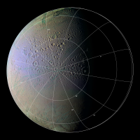
On November 27, 2016 Cassini at last obtained really good images of Enceladus' north pole during a nontargeted flyby. This is a mosaic of two IR3-GRN-UV3 color composites processed to show Enceladus in approximately natural color and in greatly exaggerated color which reveals compositional variations. A version with a latitude/longitude grid is also included.
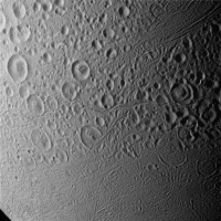
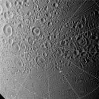
The images comprising the mosaic were obtained at a range of 62,000 to 72,000 km. ISIS3 (qnet/jigsaw) was used to correct the camera pointing. I then reprojected everything to simple cylindrical projection and rendered the images using software I wrote. The final step was to use Photoshop to process the color. The highest resolution view of the north pole obtained during this flyby is a clear filter image at a range of 32,000 km. The resolution is 190 m/pixel:
|
|||||
|
|
|
|||||
|
May 24 2018, 09:17 PM
Post
#65
|
|
|
Member Group: Members Posts: 306 Joined: 4-October 14 Member No.: 7273 |
Monochrome image mosaic of Enceladus taken during the targeted E10 flyby, at a distance of 40,000 km
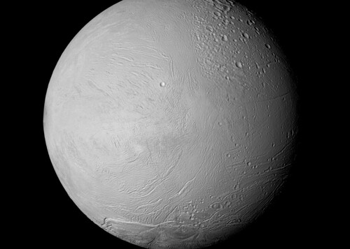 Enceladus - Rev 131 Flyby - 2010-05-18 Enceladus - Rev 131 Flyby - 2010-05-18IR3, GRN, UV3 extended color mosaic taken a little closer, from a distance of ~20,000 km. 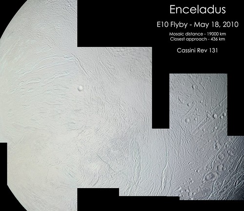 Cassini - Enceladus E10 Mosaic - Rev 131 - 05-18-2010 Cassini - Enceladus E10 Mosaic - Rev 131 - 05-18-2010Both mosaics primarily target the equatorial regions of the leading hemisphere between about 200E and 0E. |
|
|
|
 |

|
Lo-Fi Version | Time is now: 24th May 2024 - 08:33 AM |
|
RULES AND GUIDELINES Please read the Forum Rules and Guidelines before posting. IMAGE COPYRIGHT |
OPINIONS AND MODERATION Opinions expressed on UnmannedSpaceflight.com are those of the individual posters and do not necessarily reflect the opinions of UnmannedSpaceflight.com or The Planetary Society. The all-volunteer UnmannedSpaceflight.com moderation team is wholly independent of The Planetary Society. The Planetary Society has no influence over decisions made by the UnmannedSpaceflight.com moderators. |
SUPPORT THE FORUM Unmannedspaceflight.com is funded by the Planetary Society. Please consider supporting our work and many other projects by donating to the Society or becoming a member. |
|