MSL Images & Cameras, technical discussions of images, image processing and cameras |

MSL Images & Cameras, technical discussions of images, image processing and cameras |
 Aug 16 2012, 11:05 PM Aug 16 2012, 11:05 PM
Post
#1
|
||
 Senior Member  Group: Members Posts: 2228 Joined: 1-December 04 From: Marble Falls, Texas, USA Member No.: 116 |
I'm still trying to figure out a number of things about the new images we are trying to work with. Assuming others are likewise trying to learn, I thought I would open this thread to create a place for such discussions.
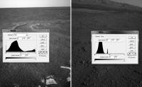
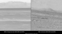
I'd like to start out with a comment about raw image contrast. There have been several postings in the main threads about whether or not the MSL raw images have been stretched like those from the MER missions. I am certainly no expert on this, but it looks to me as if the MSL images have not been stretched at all. I haven't tried to analyze all of the image types, but the hazcams and navcams have pixel brightness histograms that are very different from their MER counterparts. This attached image compares MER and MSL navcams along with their luminosity histograms.
The MSL images clearly are not using the entire, available range of brightness values, whereas the MER raws do. For this reason, the MSL raw images can usually be nicely enhanced by simply stretching the distribution of brightness across the full 256 value range. -------------------- ...Tom
I'm not a Space Fan, I'm a Space Exploration Enthusiast. |
|
 |
 
|
|
 |
|
Aug 17 2012, 02:52 PM
Post
#2
|
|
 Senior Member Group: Members Posts: 4247 Joined: 17-January 05 Member No.: 152 |
I've noticed the same thing. It means for some of these images, we're effectively getting 7 bit images. But on the other hand, the MSL images don't seem to loose detail in the whites the way MER images do.
I don't know if the MSL images have had any nonlinear pixel value transformations done, such as a logarithmic lookup table. I am curious what the images would look like with pixel value linearly related to the true scene intensity, and with the zero point correct. |
|
|
|
|
Aug 18 2012, 05:53 AM
Post
#3
|
||
|
Senior Member Group: Members Posts: 2228 Joined: 1-December 04 From: Marble Falls, Texas, USA Member No.: 116 |
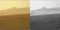
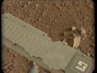
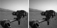
I'm curious about something I am seeing in the mastcam color images (M-34) and hope someone here can explain it. I'm not sure if this is the correct term, but I am seeing what appears to be color banding in most of the color mastcams. It is more apparent in some than others, and if you split the color image into it's red, green, and blue channels it becomes even more apparent.
In the attached example I have put the red channel greyscale alongside the color image. I have contrast stretched both images to make the banding effect more apparent.
My best guess is that this may be caused by the raw images having had their bit depth reduced at some point. Or, could this be caused by some kind of image compression? -------------------- ...Tom
I'm not a Space Fan, I'm a Space Exploration Enthusiast. |
|
|
|
|
|
|
Aug 18 2012, 06:00 AM
Post
#4
|
|
 Member Group: Members Posts: 345 Joined: 2-May 05 Member No.: 372 |
That's the JPEG compression having an aneurysm.

|
|
|
|
|
Aug 18 2012, 10:45 PM
Post
#5
|
|
|
Junior Member Group: Members Posts: 36 Joined: 28-May 08 Member No.: 4152 |
QUOTE (um3k @ Aug 18 2012, 07:00 AM)  That's the JPEG compression having an aneurysm. Something I've been wondering about - are the Mastcam, MARDI and MAHLI JPEG images being recompressed on Earth, or is this JPEG data originally produced on Mars? (I read somewhere on these fine forums that the Navcams use some fancy wavelet compression, but the colour cameras use good old JPEG. I'd love it if some of the raw images were literally that - identical data to that produced on another planet. Being repackaged and recompressed into a more web-friendly form is much more likely, alas...) Pointlessly, I did check an image for EXIF tags, just in case - unsurprisingly there's nothing exciting. CODE Spiral:Desktop afoster$ jhead 0003ML0000124000E1_DXXX.jpg File name : 0003ML0000124000E1_DXXX.jpg File size : 132864 bytes File date : 2012:08:18 15:35:06 Resolution : 1200 x 1200 Comment : NASA/JPL-Caltech/Malin Space Science Systems Transmitting data like the manufacturer's name, camera serial number, focal length and whatever, over and over again, could be deemed an unnecessary use of interplanetary bandwidth? Shame. I imagine useful metadata takes a different route.  |
|
|
|
|
Aug 18 2012, 10:50 PM
Post
#6
|
|
|
Member Group: Members Posts: 345 Joined: 2-May 05 Member No.: 372 |
QUOTE (Cargo Cult @ Aug 18 2012, 06:45 PM) Something I've been wondering about - are the Mastcam, MARDI and MAHLI JPEG images being recompressed on Earth, or is this JPEG data originally produced on Mars? At least some of the images are compressed in-rover, but I suspect these glaring artifacts are the result of recompression for the web. Especially since the data is almost certainly transmitted as a grayscale image with an intact bayer pattern. It'd be rather silly to debayer it on Mars and triple the amount of data that needs sent. |
|
|
|
|
Aug 18 2012, 11:04 PM
Post
#7
|
|
 Senior Member Group: Members Posts: 3648 Joined: 1-October 05 From: Croatia Member No.: 523 |
QUOTE (um3k @ Aug 19 2012, 12:50 AM) It'd be rather silly to debayer it on Mars and triple the amount of data that needs sent. ... except that's pretty much exactly what the cameras do onboard, de-Bayer is applied and JPEG-compressed as that's the lossy compression scheme of choice. Probably every single color image returned so far used this approach. It's not 3x the amount of data because its compressed in a lossy way and the chrominance channels are subsampled. In fact, this approach of exploiting visual similarity between what would otherwise be 3 similar b/w images encoded separately might by itself reduce bits-per-pixel requirement for a given image quality, even with no chrominance subsampling. -------------------- |
|
|
|
|
Aug 18 2012, 11:16 PM
Post
#8
|
|
|
Member Group: Members Posts: 345 Joined: 2-May 05 Member No.: 372 |
I suppose that sort of makes sense. It makes the photographer in me cringe, and explains the sub-par demosaicing, but I understand the logic behind it. As someone who frequently deals with video encoding, I'm well aware of the relative compression efficiency of redundant data.
|
|
|
|
|
Aug 18 2012, 11:48 PM
Post
#9
|
|
|
Senior Member Group: Members Posts: 2517 Joined: 13-September 05 Member No.: 497 |
QUOTE (um3k @ Aug 18 2012, 04:16 PM) I suppose that sort of makes sense. It makes the photographer in me cringe, and explains the sub-par demosaicing, but I understand the logic behind it. Gee, thanks for the ringing endorsement. ugordan has it all correct. A complete description of MMM compression can be found in the Space Science Reviews paper on MAHLI -- http://rd.springer.com/article/10.1007/s11214-012-9910-4 -- see section 7.5 "Image Compression".We can return uninterpolated frames if we want to pay the downlink volume penalty. I haven't verified this but I suspect that the web release images are going through a decompress/recompress cycle. -------------------- Disclaimer: This post is based on public information only. Any opinions are my own.
|
|
|
|
|
Aug 18 2012, 11:55 PM
Post
#10
|
|
|
Member Group: Members Posts: 345 Joined: 2-May 05 Member No.: 372 |
I mean no offense, in fact I greatly admire you and the rest of the MSSS team. You've (collectively and individually) accomplished some amazing things. I just have a rather negative gut reaction to lossy compression.
 EDIT: Also, about the demosaicing: I'm quite certain you know what you're doing. I'm referring to the anomalous horizontal lines in the MARDI images, which I assume (perhaps mistakenly) have to do with the demosaicing, the quality of which I (again) assume is limited by the limited processing power/time of the rover. I also fully realize that more complex, non-linear interpolation algorithms aren't very conducive to scientific analysis. Perhaps my excessive assumptions are correlated with the fact that the MSSS team has cameras in space, while I have a desk cluttered with scavenged optics and a spectrograph made of LEGO bricks and a mutilated DVD-R.
|
|
|
|
|
Aug 19 2012, 02:51 PM
Post
#11
|
|
|
Newbie Group: Members Posts: 2 Joined: 6-August 12 Member No.: 6478 |
The signal to noise ratio and information content of this forum is outstanding. Let me contribute a small bit by providing links to technical documents about some of the MSL cameras, documents I found in the process of researching the MSL's computer system and internal network (about which I found virtually nothing):
The Mars Science Laboratory Engineering Cameras http://www-robotics.jpl.nasa.gov/publicati...ne/fulltext.pdf THE MARS SCIENCE LABORATORY (MSL) NAVIGATION CAMERAS (NAVCAMS) http://www.lpi.usra.edu/meetings/lpsc2011/pdf/2738.pdf THE MARS SCIENCE LABORATORY (MSL) HAZARD AVOIDANCE CAMERAS (HAZCAMS) http://www.lpi.usra.edu/meetings/lpsc2012/pdf/2828.pdf THE MARS SCIENCE LABORATORY (MSL) MARS DESCENT IMAGER (MARDI) FLIGHT INSTRUMENT http://www.lpi.usra.edu/meetings/lpsc2009/pdf/1199.pdf THE MARS SCIENCE LABORATORY (MSL) MARS HAND LENS IMAGER (MAHLI) FLIGHT INSTRUMENT http://www.lpi.usra.edu/meetings/lpsc2009/pdf/1197.pdf ---------- Some interesting heat shield documents: MEDLI System Design Review Project Overview http://www.mrc.uidaho.edu/~atkinson/Senior...ct_Overview.pdf Advances in Thermal Protection System Instrumentation for Atmospheric Entry Missions http://www.mrc.uidaho.edu/~atkinson/ECE591...ntations/Fu.ppt A relatively short but very interesting document about the engineering challenges of landing on Mars which discusses the advantages and disadvantages of the various possible methods: http://www.engineeringchallenges.org/cms/7126/7622.aspx As I said, I found virtually nothing about the Mars Compute Element (MCE) and the network(s) used within the lander to control MSL hardware (anyone know a good source, the more technical the better?), but I did find a tiny bit within this document starting on p41 where the electronics architecture is discussed. The bus used is redundant 2Mbps RS-422. The SAM uses BASIC keywords for its command language!: The Sample Analysis at Mars Investigation and Instrument Suite http://www.springerlink.com/content/p26510...08/fulltext.pdf Excerpt: The (SAM) CDH (Command and Data Handling) module (Fig.16) includes a number of functions. The CPU is the Coldfire CF5208 running at 20 MHz. The CDH (module) communicates with the Rover via redundant 2 Mbps high speed RS-422 serial bus along with a discrete interface (NMI). In the SAM software description starting on p47, I found this interesting tidbit: SAMs command system is a radical departure from prior spaceflight instrumentation. SAM is a BASIC interpreter. Its native command language encompasses the complete set of BASIC language constructsFOR-NEXT, DO-WHILE, IF-ENDIF, GOTO and GOSUBas well as a large set of unique built-in commands to perform all the specific functions necessary to configure and operate the instrument in all its possible modes. SAMs commands, which are BASIC commands with SAM-specific commands built in, are transmitted in readable ASCII text. This eliminates the need for a binary translation layer within the instrument command flow, and makes it possible for operators to directly verify the commands being transmitted. There are more than 200 commands built in to the SAM BASIC script language. ---------- And even though this is just a NASA Press Kit, it is satisfyingly detailed technically on various MSL systems: Mars Science Laboratory Landing http://mars.jpl.nasa.gov/msl/news/pdfs/MSLLanding.pdf And just for the heck of it, here's NASA's Viking Press Kit. How very far we have come, even with press kits: http://mars.jpl.nasa.gov/msl/newsroom/presskits/viking.pdf |
|
|
|
|
Aug 19 2012, 04:29 PM
Post
#12
|
|
|
Merciless Robot Group: Admin Posts: 8784 Joined: 8-December 05 From: Los Angeles Member No.: 602 |
Welcome, Winston, and thanks for a terrific first post!
We may archive some of those links in the MSL FAQ thread; much appreciated!
-------------------- A few will take this knowledge and use this power of a dream realized as a force for change, an impetus for further discovery to make less ancient dreams real.
|
|
|
|
|
Aug 24 2012, 08:02 PM
Post
#13
|
|
|
Senior Member Group: Members Posts: 2517 Joined: 13-September 05 Member No.: 497 |
QUOTE (Holger Isenberg @ Aug 24 2012, 11:48 AM) Now the question is: Which is the actual transmissin curve of the IR cutoff filter? The one (black dotted line) in the 2541.pdf or the one (thick dark green line) on the JPL-Mastcam web page? The plot in 2541.pdf is not a transmission curve, it's a response curve and thus modulated by the detector QE. The JPL web page looks pretty close. -------------------- Disclaimer: This post is based on public information only. Any opinions are my own.
|
|
|
|
|
Aug 24 2012, 08:30 PM
Post
#14
|
|
|
Newbie Group: Members Posts: 2 Joined: 19-August 12 Member No.: 6589 |
QUOTE (mcaplinger @ Aug 24 2012, 10:02 PM) The plot in 2541.pdf is not a transmission curve, it's a response curve and thus modulated by the detector QE. The JPL web page looks pretty close. Thanks for pointing that out! So the overall effect is like adding a strong UV filter to a normal digital camera, like a LP 420, which is actually helping to reduce visual haze. However, what explains then the decrease of the blue response function maxima at 470nm to almost 30% with the green response being the 100% reference on the black dotted line in 2541.pdf? |
|
|
|
|
Aug 24 2012, 09:25 PM
Post
#15
|
|
|
Senior Member Group: Members Posts: 2517 Joined: 13-September 05 Member No.: 497 |
QUOTE (Holger Isenberg @ Aug 24 2012, 01:30 PM) However, what explains then the decrease of the blue response function maxima at 470nm to almost 30% with the green response being the 100% reference on the black dotted line in 2541.pdf? I'm not sure what the dashed line is really supposed to mean. The IR-cutoff response is shown in blue, green, and red, but all the filters have been normalized to their peaks, so you can't, for example, compare the R2/L2 narrowband response to the IR-cutoff blue response, or the IR-cutoff blue to the red. This plot was just intended to give an outline of where the bandpasses are. -------------------- Disclaimer: This post is based on public information only. Any opinions are my own.
|
|
|
|
|
Aug 25 2012, 11:29 AM
Post
#16
|
|||
|
Senior Member Group: Members Posts: 3648 Joined: 1-October 05 From: Croatia Member No.: 523 |
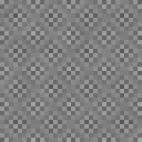
This is just for fun, I tried to implement an adaptive correction for the JPEGged (ugh!), raw Bayered images to get rid of artifacts in image areas that are smooth in appearance. The artifacts come from the JPEG algorithm trashing the Bayer pattern, introducing this kind of pattern:
After correcting for that, the smooth areas became more smooth as illustrated by this comparison, although obviously this approach can't ever come close to an image already returned from the spacecraft in de-Bayered, color form:
I had to make the algorithm adaptive in picking which DCT blocks it will apply this to, because if I apply that correction invariably across the image, some uniform-color areas which originally already looked good had these artifacts introduced afterwards... -------------------- |
||
|
|
|
||
|
Aug 25 2012, 06:32 PM
Post
#17
|
|||
 Member Group: Members Posts: 408 Joined: 3-August 05 Member No.: 453 |
Here is a poor man's way of de-Bayering Mastcam images using the Gimp (or similar tools) for those wanting to experiment a little - obviously not intended for the experts here! I realize it is not as sophisticated as proper implementations, but in the absence of a Gimp plugin, this way has the advantage of simplicity at the expense of ending up with a half-resolution image. It does not for instance use just the green pixels for luminosity, and it performs the chroma filtering by the simple expedient of scaling the image down by a factor of 2 (thus merging each set of red, blue and two green pixels together).
Airbag Bayer pattern color map image:
Sample result:
|
||
|
|
|
||
|
Aug 25 2012, 08:54 PM
Post
#18
|
||||
|
Senior Member Group: Members Posts: 4247 Joined: 17-January 05 Member No.: 152 |
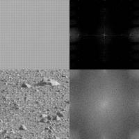
Here's the FFT of the jpeged Bayer patterns, upper two are a patch of smooth sky, and lower two a patch of ground:
In the ground image, you only see 2-pixel-scale (rough) periodicity, corresponding to the Bayer pattern, which shows up as broad peaks at the edges of the FFT. In the sky image, you also see peaks at the 2-pixel scale at the edges of the FFT, but sharp now since the sky is smooth. And you can also see FFT peaks halfway and quarter way to the edges, corresponding to 4- and 8-pixel periodicity. But of course there should be no 4 or 8 pixel periodicity in a smooth Bayer image! So clearly those peaks are the result of jpegging. So I tried to filter out those peaks in the power spectrum. Here's the result on the same image as ugordan used:
Very similar result! The Fourier space filtering beautifully gets rid of the blotchy pattern on large smooth areas, but breaks down at the edges of those areas since the periodicity breaks down there. But there was no need to make the algorithm adaptive here - it works in one simple step. Here's the horizon shot:
Again, a great job on the sky, but very little improvement on the not-so-periodic blotches over the mound. |
|||
|
|
|
|||
|
Aug 25 2012, 09:35 PM
Post
#19
|
|
|
Senior Member Group: Members Posts: 3516 Joined: 4-November 05 From: North Wales Member No.: 542 |
I'm totally fascinated by the various approaches to de-Bayering being tried out and discussed here, and that's from somebody not normally interested in the details of image processing techniques. I've learned a lot from the many posts, especially ugordan's and now fredk's. I love Airbag's slicing of the gordian knot for a quick short cut. Who says airbags are no use on this mission?
|
|
|
|
|
Aug 26 2012, 04:25 PM
Post
#20
|
|
|
Member Group: Members Posts: 122 Joined: 19-June 07 Member No.: 2455 |
I hope this is the right section for this. I'm actually replying to a post in another thread but, since it's about image processing, thought it better to put it here.
Amazing comparing the Hirise anaglyph to what we actually see on the ground. One thing that seems to be obvious to me though is that there is a real exaggeration of relief in the Hirise 3D effect (mesa are taller, canyons are deeper) most likely created because the left and right images are taken a great deal farther apart than the human eyes. If I understand they are simply images taken at different points in the orbit and not by two cameras side by side as on the rovers. While that relief is stunning and produces this amazing view of surface from above, it is not really a true representation as to what a human observer would see from orbit. In these days of phenomenal image and video processing software, where a program can build intermediate frames of a video by analyzing the pixels of each surrounding frame, I wonder if someone hasn't devised a way of correcting the relief of a 3D anaglyph if one knows the actual separation of the two images. I can certainly picture the code process in my mind and it doesn't seem complicated if one works with image comparison coding. I'm a computer programmer but it's been years since I did anything where I was manipulating pixels and my relearning curve would be extensive or I'd tackle something myself. Sure seems that anaglyphs have been around long enough that someone would have figured this out by now. Any thoughts? QUOTE (walfy @ Aug 26 2012, 02:21 AM) I borrowed Fred's excellent rendition to compare with HiRISE anaglyph of the prime science region around the inverted riverbed. It's a very narrow angle of view. If I marked some features wrong, please let me know. [attachment=27716:msl_science_target.jpg] |
|
|
|
|
Aug 26 2012, 04:35 PM
Post
#21
|
|
|
Solar System Cartographer Group: Members Posts: 10166 Joined: 5-April 05 From: Canada Member No.: 227 |
I don't do anaglyphs so I can't get technical here, but basically the 3-D map created by a stereo pair can be displayed with any vertical exaggeration you like. Typically they are made with some exaggeration because most scenes are rather bland without it. For a given stereo pair there may be some default value that is normally used but it could be changed if desired.
Phil -------------------- ... because the Solar System ain't gonna map itself.
Also to be found posting similar content on https://mastodon.social/@PhilStooke Maps for download (free PD: https://upload.wikimedia.org/wikipedia/comm...Cartography.pdf NOTE: everything created by me which I post on UMSF is considered to be in the public domain (NOT CC, public domain) |
|
|
|
|
Aug 26 2012, 05:09 PM
Post
#22
|
|
|
Senior Member Group: Members Posts: 3516 Joined: 4-November 05 From: North Wales Member No.: 542 |
QUOTE (Art Martin @ Aug 26 2012, 05:25 PM) I wonder if someone hasn't devised a way of correcting the relief of a 3D anaglyph We've discussed this here a while ago, but rather than try to dig back for that here are a couple of salient points. Anaglyphs don't have a constant intrinsic exaggeration factor. The apparent relief you see depends on the size of the image and the distance you view it from. Adjust those and you could in theory view any anaglyph without line-of sight exaggeration. It's true that in many cases you'd have to enlarge the image enormously and sit very close to it!! One solution I've suggested is the inclusion of a small virtual cube in the corner of each anaglyph to serve as a three dimensional scale bar, so if the cube looks too tall you know you're seeing the scene exaggerated by the same amount. |
|
|
|
|
Aug 26 2012, 05:17 PM
Post
#23
|
|
|
Senior Member Group: Members Posts: 4247 Joined: 17-January 05 Member No.: 152 |
I think what Art's suggesting is adjusting the apparent relief while keeping viewing size/distance constant. I could imagine doing that, for example by morphing one frame part ways towards the other to reduce relief. But that would be hard and would involve some degree of faking for the intermediate viewpoints.
For now, ngunn's approach can at least help reduce exagerated relief. |
|
|
|
|
Aug 26 2012, 05:55 PM
Post
#24
|
|
 Member Group: Members Posts: 700 Joined: 3-December 04 From: Boulder, Colorado, USA Member No.: 117 |
QUOTE (ngunn @ Aug 26 2012, 11:09 AM) It's true that in many cases you'd have to enlarge the image enormously and sit very close to it!! Actually, does enlarging the image have any effect on the apparent vertical exaggeration? I wouldn't expect so, because there should be no vertical exaggeration when the convergence angle of your eyes matches the convergence angle of the original image pair [convergence angle = angle between the two lines of sight in the stereo pair, measured at the surface location being viewed]. The convergence angle of your eyes depends on their distance from the image, but doesn't depend on the image magnification. John |
|
|
|
|
Aug 26 2012, 06:59 PM
Post
#25
|
||
 The Insider Group: Members Posts: 669 Joined: 3-May 04 Member No.: 73 |
Here's my attempt at creating a 3d anaglyph image of the distant hills...
Attached thumbnail(s)
|
|
|
|
|
|
|
Aug 26 2012, 07:49 PM
Post
#26
|
|
|
Senior Member Group: Members Posts: 3516 Joined: 4-November 05 From: North Wales Member No.: 542 |
QUOTE (john_s @ Aug 26 2012, 06:55 PM) Actually, does enlarging the image have any effect on the apparent vertical exaggeration? I wouldn't expect so You are correct of course. It's the viewing distance alone that does it. I was confusing anaglyphs with cross-eyed pairs where the size does have an effect because it changes the angles too. QUOTE (Pando @ Aug 26 2012, 07:59 PM) Here's my attempt at creating a 3d anaglyph image of the distant hills. Excellent! |
|
|
|
|
Aug 26 2012, 08:09 PM
Post
#27
|
|
|
Member Group: Members Posts: 122 Joined: 19-June 07 Member No.: 2455 |
Yes, that's exactly what I was wondering about. It would very much involve faking one of the images based on an analysis of an anaglyph created with the wider separation of views and then rebuilding the anaglyph with one original and the "faked" image. I guess derived image would be a more PC term much like when smoothing a video shot at low FPS and having the computer generate the intermediate images for a standard video frame rate based on a best guess of how motion and scaling would occur in each frame. When I've created anaglyphs in the past, the two original images are lined up vertically first and then the images are aligned horizontally for the most comfortable view. This results in a blue and a red tinted image combining both of the originals. When you view it without the glasses you can see distinct blue and red tinted objects with close up ones having more horizontal distance between those objects and the far away ones having very little distance or they're essentially right on top of one another. When the left and right image are taken at let's say hundreds of miles apart those distances get very exaggerated when viewed by human eyes. What the program would do would be figure out how much offset each pixel on let's say the right image shifted to the side from it's corresponding pixel on the left image and bring it back closer together in the proportion between a standard eye viewing angle and the actual image angles. I'd think that would be fairly easy to do on a long distant aerial shot but very tough on something close up because objects could block other ones from left to right. So guess this is a challenge to the programmers that have written the wonderful anaglyph software out there that pretty much assumes the original shots are taken at standard eye distance. They're already really doing the processing when they build the final red/blue image. You'd just need one more parameter in there that was the distance between the original images. Instead of simply combining the shots together, the blue portion would be derived and then combined.
One advantage of having this feature would be that you could also intentionally exaggerate the relief by creating the derived image at a much wider distance than it was originally shot to more readily spot depressions and things jutting up. QUOTE (fredk @ Aug 26 2012, 10:17 AM) I think what Art's suggesting is adjusting the apparent relief while keeping viewing size/distance constant. I could imagine doing that, for example by morphing one frame part ways towards the other to reduce relief. But that would be hard and would involve some degree of faking for the intermediate viewpoints. For now, ngunn's approach can at least help reduce exagerated relief. |
|
|
|
|
Aug 26 2012, 08:43 PM
Post
#28
|
|
 Senior Member Group: Admin Posts: 4763 Joined: 15-March 05 From: Glendale, AZ Member No.: 197 |
QUOTE (ugordan @ Aug 25 2012, 04:29 AM) This is just for fun, I tried to implement an adaptive correction for the JPEGged (ugh!), raw Bayered images Very ingenuitive thinking Gordan -- and it seems to have worked well. -------------------- If Occam had heard my theory, things would be very different now.
|
|
|
|
|
Aug 27 2012, 08:22 PM
Post
#29
|
|
|
Member Group: Members Posts: 121 Joined: 26-June 04 From: Austria Member No.: 89 |
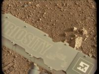
A few remarks about the near focus of the mastcams:
The pictures of the sundial taken by the mastcam-100 are not in focus up to now. I suspect that the near focus of this camera is a little bit beyond - for example the cable that running left of the dial is sharp: http://mars.jpl.nasa.gov/msl-raw-images/ms...1000E1_DXXX.jpg In contrast the m34 has taken sundial pictures that are in best focus: http://mars.jpl.nasa.gov/msl-raw-images/ms...0000E1_DXXX.jpg Did anyone know the distance from the mastcams to the dial ? Robert |
|
|
|
|
Aug 27 2012, 08:55 PM
Post
#30
|
|
|
Senior Member Group: Members Posts: 2517 Joined: 13-September 05 Member No.: 497 |
QUOTE (Roby72 @ Aug 27 2012, 01:22 PM) Did anyone know the distance from the mastcams to the dial ? The Marsdial is roughly 7.6 cm square and one side is 296 pixels long in the 34mm image. The IFOV of the 34mm is about 218 microrads, so the distance is roughly 1.2 meters. -------------------- Disclaimer: This post is based on public information only. Any opinions are my own.
|
|
|
|
|
Aug 28 2012, 12:12 AM
Post
#31
|
||
|
Member Group: Members Posts: 808 Joined: 10-October 06 From: Maynard Mass USA Member No.: 1241 |
Back from a little vacation, and catching up on all the threads.
After several attempts to circumvent the JPEG induced color/pattern bleeds in the bayers, I decided to just make a good B&W image. It has several hacks: rank order adaptive noise reduction, reduced resolution to 50%, and multiple stacks. (and its not that good) 
... maybe MSSS will take pity on the collective suffering and hacks found here on these threads and authorize a posting of a few PNG raw bayers (just to see if all of the UMSF debayer programs are working properly of course!) -------------------- CLA CLL
|
|
|
|
|
|
|
Aug 28 2012, 12:49 AM
Post
#32
|
|
|
Senior Member Group: Members Posts: 2517 Joined: 13-September 05 Member No.: 497 |
QUOTE (PDP8E @ Aug 27 2012, 05:12 PM) ... maybe MSSS will take pity on the collective suffering and hacks found here on these threads and authorize a posting of a few PNG raw bayers... What would be more in keeping with the spirit of the data release policy (IMHO) would be for us to demosaic the data and then JPEG that, but I can't do either one without permission. If raw data acquisition becomes common I'll ask, but I don't think it's worth it for a relative handful of images. -------------------- Disclaimer: This post is based on public information only. Any opinions are my own.
|
|
|
|
|
Aug 28 2012, 04:06 AM
Post
#33
|
|
|
Senior Member Group: Admin Posts: 4763 Joined: 15-March 05 From: Glendale, AZ Member No.: 197 |
Sounds like a great task for a trusted college intern.
-------------------- If Occam had heard my theory, things would be very different now.
|
|
|
|
|
Aug 28 2012, 04:44 AM
Post
#34
|
|
|
Senior Member Group: Members Posts: 2517 Joined: 13-September 05 Member No.: 497 |
QUOTE (ElkGroveDan @ Aug 27 2012, 09:06 PM) Sounds like a great task for a trusted college intern. I have no idea what your point is. It would take me about a minute to process all these images and post them. It's the permission to do so that's lacking. -------------------- Disclaimer: This post is based on public information only. Any opinions are my own.
|
|
|
|
|
Aug 28 2012, 07:30 AM
Post
#35
|
|
|
Member Group: Members Posts: 890 Joined: 18-November 08 Member No.: 4489 |
the jpg issue is mostly solved
http://imgbox.com/g/9pzCUh6YaZ ------------  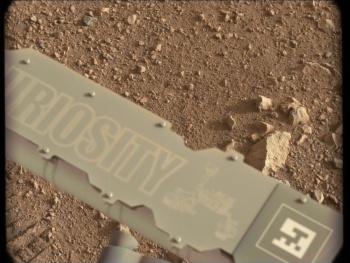   ------------- not "white balanced" the code used CODE gmic 0017MR0050002000C0_DXXX.jpg -bayer2rgb 3,3,3 -pde_flow 5,20 -sharpen 2 -o 0017MR0050002000C0.png a pde to remove most of the artifacts |
|
|
|
|
Aug 28 2012, 07:57 AM
Post
#36
|
|
|
Senior Member Group: Members Posts: 3648 Joined: 1-October 05 From: Croatia Member No.: 523 |
QUOTE (mcaplinger @ Aug 28 2012, 06:44 AM) It's the permission to do so that's lacking. I can understand that posting raws as PNGs would be iffy because we'd be getting the same quality product as you, but why would de-Bayering on the ground and JPEG-ing present an issue? -------------------- |
|
|
|
|
Aug 28 2012, 07:59 AM
Post
#37
|
|
|
Senior Member Group: Members Posts: 3648 Joined: 1-October 05 From: Croatia Member No.: 523 |
QUOTE (JohnVV @ Aug 28 2012, 09:30 AM) the jpg issue is mostly solved John, that looks very smooth, but there's an obvious loss of sharpness in the resulting images. -------------------- |
|
|
|
|
Aug 28 2012, 09:40 AM
Post
#38
|
||
|
Newbie Group: Members Posts: 2 Joined: 13-September 11 Member No.: 6155 |
QUOTE (ugordan @ Aug 28 2012, 09:59 AM) John, that looks very smooth, but there's an obvious loss of sharpness in the resulting images. Ive attached a waveletsharpened version of one of the PNG's, its possible to resharpen them without too much of the debayer-artefacts showing up it seems. cheers CorB
|
|
|
|
|
|
|
Aug 28 2012, 10:08 AM
Post
#39
|
|
 Senior Member Group: Members Posts: 1465 Joined: 9-February 04 From: Columbus OH USA Member No.: 13 |
I wonder what the effective bits per pixel of the MASTCAM raw images is. The cameras use the KODAK KAI-2020CM sensor. Is it sampled with a 12-bit ADC like MARDI and NAVCAM? One reference for NAVCAM gives an SNR of >200 for certain conditions. So that would mean effectively 7-8 bits per pixel for that camera anyway?
It was interesting that yesterday Mike Malin referred to stacking images. -------------------- |
|
|
|
|
Aug 28 2012, 01:48 PM
Post
#40
|
|
|
Senior Member Group: Members Posts: 2517 Joined: 13-September 05 Member No.: 497 |
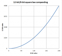
QUOTE (jmknapp @ Aug 28 2012, 03:08 AM) I wonder what the effective bits per pixel of the MASTCAM raw images is. The MAHLI paper I've referred to several times before is an excellent source of this kind of information. From section 7.5.1: "Acquired as 12-bit images, MAHLI data are converted onboard the instrument, without loss of information, to 8-bit images using a square-root companding look-up table." -------------------- Disclaimer: This post is based on public information only. Any opinions are my own.
|
|
|
|
|
Aug 28 2012, 02:03 PM
Post
#41
|
|
|
Senior Member Group: Members Posts: 2517 Joined: 13-September 05 Member No.: 497 |
QUOTE (ugordan @ Aug 28 2012, 12:57 AM) why would de-Bayering on the ground and JPEG-ing present an issue? I am not authorized to put any data out, in any form. You might want to take a look at http://blogs.agu.org/martianchronicles/201...8/blogging-msl/ -- Ryan discusses in general terms the rules that we operate under. I am constantly evaluating each of my posts to make sure that it is only derived from public information. If you don't like it, complain to my boss. -------------------- Disclaimer: This post is based on public information only. Any opinions are my own.
|
|
|
|
|
Aug 28 2012, 02:39 PM
Post
#42
|
|
|
Member Group: Members Posts: 408 Joined: 3-August 05 Member No.: 453 |
QUOTE (mcaplinger @ Aug 28 2012, 08:48 AM) "Acquired as 12-bit images, MAHLI data are converted onboard the instrument, without loss of information, to 8-bit images using a square-root companding look-up table." I read that a while back and was puzzled by how one could do any such conversion without a loss of information unless the original data already fit in 8 bits? Any non-trivial processing operation results in a loss of information somewhere (usually with the purpose of increasing apparent information somewhere else). I understand companding and all that, but that is not a two-way operation without loss of information. The resulting 8 bit data cannot be converted back into the original 12 bit data, surely, as multiple values in the 12 bit sample get mapped to the same 8 bit value? Just trying to understand what exactly was meant in the MAHLI document. Airbag |
|
|
|
|
Aug 28 2012, 03:05 PM
Post
#43
|
|
|
Member Group: Members Posts: 910 Joined: 4-September 06 From: Boston Member No.: 1102 |
mcaplinger We all really appreciate the fantastic images released and I think the misundrstanding was that you are bound by image release policy--not being the one doing the releasing. After the appropriate time, the eager ones here will have access to raw data.
Airbag I'm not an expert, but I think it means without loss of spatial resolution. Clearly there is minor loss of brightness precisionin/pixl going from 12 to 8 bit (and back again). However, visually, 8 bit square-root gives full dynamic range and preserves the low-light/dark range preferentially to the saturated white end. -------------------- |
|
|
|
|
Aug 28 2012, 03:09 PM
Post
#44
|
|
|
Senior Member Group: Members Posts: 3648 Joined: 1-October 05 From: Croatia Member No.: 523 |
Airbag, also look up photon shot noise to see why even 12 to 8 bit conversion is "sorta" lossless.
-------------------- |
|
|
|
|
Aug 28 2012, 04:17 PM
Post
#45
|
|
|
Member Group: Members Posts: 408 Joined: 3-August 05 Member No.: 453 |
Ugordan,
But photon shot noise is less of an issue with larger number of photons (i.e. higher CCD signal levels) and that is exactly where a square root compander "does its thing" the most, so I don't see how photon shot noise would be relevant to my original question? I could understand it if the CCD read noise was a dominant factor, and thus the 12 bits of data are really only "effectively" worth around 8 bits, but that would imply a huge noise contribution! Airbag |
|
|
|
|
Aug 28 2012, 04:22 PM
Post
#46
|
|
|
Senior Member Group: Members Posts: 2517 Joined: 13-September 05 Member No.: 497 |
QUOTE (Airbag @ Aug 28 2012, 09:17 AM) But photon shot noise is less of an issue with larger number of photons... shot noise = sqrt(signal), so shot noise is higher at higher signal levels. The square root encoding is coarser at higher levels, finer at lower levels. You could have a philosophical debate about what this means, but that's the way our cameras work. -------------------- Disclaimer: This post is based on public information only. Any opinions are my own.
|
|
|
|
|
Aug 28 2012, 06:30 PM
Post
#47
|
|
|
Member Group: Members Posts: 408 Joined: 3-August 05 Member No.: 453 |
I was looking at shot noise from a S/N point of view but I get the hint and will skip any debates - thanks for the clarifications everybody!
Airbag |
|
|
|
|
Aug 28 2012, 07:47 PM
Post
#48
|
|
|
Senior Member Group: Members Posts: 1465 Joined: 9-February 04 From: Columbus OH USA Member No.: 13 |
QUOTE (mcaplinger @ Aug 28 2012, 08:48 AM) The MAHLI paper I've referred to several times before is an excellent source of this kind of information. http://rd.springer.com/article/10.1007/s11...4/fulltext.html From another paper.... QUOTE MAHLI shares common electronics, detector, and software designs with the MSL Mars Descent Imager (MARDI) and the two Mast Cameras (Mastcam). Ahh, good to know. Wonder what the (optimum) SNR is. -------------------- |
|
|
|
|
Aug 28 2012, 08:25 PM
Post
#49
|
|
|
Senior Member Group: Members Posts: 2517 Joined: 13-September 05 Member No.: 497 |
QUOTE (jmknapp @ Aug 28 2012, 12:47 PM) Wonder what the (optimum) SNR is. I often tell people who are fond of such numeric metrics as SNR, MTF, ENOB, etc, that no matter how optimal those numbers make your camera sound, anybody can tell a good image from a bad image. I think the MMM images hold up pretty well. That said, you could work out the best possible SNR we could get from the Truesense datasheet. You can't ever do better than sqrt(fullwell) for a single measurement due to shot noise and these sensors have a fullwell of 20K-40K electrons so 140:1 to 200:1 is as good as it could be. -------------------- Disclaimer: This post is based on public information only. Any opinions are my own.
|
|
|
|
|
Aug 29 2012, 12:32 AM
Post
#50
|
|
|
Senior Member Group: Members Posts: 1465 Joined: 9-February 04 From: Columbus OH USA Member No.: 13 |
QUOTE (mcaplinger @ Aug 28 2012, 04:25 PM) these sensors have a fullwell of 20K-40K electrons so 140:1 to 200:1 is as good as it could be. 200:1 is about 46 dB SNR which according to the method on ctecphotonics gives effective number of bits (ENOB) of (46-2)/6 = 7.3 bits. That could be improved if desired by stacking? The images are very impressive to see--just wondering what the limits are when the images are considered as abstract data, perhaps to be analyzed by machines teasing out the last bit of information. -------------------- |
|
|
|
|
Aug 29 2012, 06:44 PM
Post
#51
|
||
|
Member Group: Members Posts: 408 Joined: 3-August 05 Member No.: 453 |
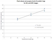
That explains it all Joe - thanks! This made me wonder if the public "raw" images we see are uncompanded (and rescaled into 8 bits) again or not?
As an experiment, I used some full size ML and MR color images of the sundial, which has gray rings of 20%, 40% and 60% reflectivity, and measured the corresponding grayscale pixel values using "sample merged" data point of appropriate radii in the Gimp. Making various assumptions about JPEG accuracy, lighting and dust etc. (i.e. ignoring them!), the resulting data shows that the JPEGs we see appear to be quite linear in response to the different grayscale rings. This suggest that the images we see has been decompanded - unless either my measurements are flawed (for instance, the extrapolation of the trend does not go through the origin), or the CCD is not really linear in response, and the MSL side companding has now made it appear linear?
Comments welcome, as if I could stop them anyway :-) Airbag |
|
|
|
|
|
|
Aug 29 2012, 07:01 PM
Post
#52
|
||
|
Senior Member Group: Members Posts: 1465 Joined: 9-February 04 From: Columbus OH USA Member No.: 13 |
QUOTE (Airbag @ Aug 29 2012, 02:44 PM) ... the JPEGs we see appear to be quite linear in response to the different grayscale rings. Interesting use of a test pattern. I gather the square law companding from 12-bit to 8-bit would be something like this:
The image you used ranged from about 100-160--not sure if you'd notice the nonlinearity per the graph above. I.e., does it only matter if there's a lot of dynamic range in the image, otherwise it can be pretty much fixed up with linear levels adjustments? -------------------- |
|
|
|
|
|
|
Aug 29 2012, 07:29 PM
Post
#53
|
|
|
Member Group: Members Posts: 408 Joined: 3-August 05 Member No.: 453 |
Joe, I think you may have the wrong "law" - it should be square root, not square, right? Doesn't change your plot though, and maybe that is just a semantics thing.
You may well be correct that the dynamic range of my samples (from 5 different images) is not sufficient to show whether the resulting data is truly linear or not. Plus, even a little bit of dust would cause more forward scattering and that could be why my data points don't go through the origin. Arguably. I could have included some (presumed) "full white" and "full black" (the gnomon?) points too, but I have no data for actual reflectivity values for anything other than the gray rings. Airbag |
|
|
|
|
Aug 29 2012, 07:37 PM
Post
#54
|
|
|
Senior Member Group: Members Posts: 4247 Joined: 17-January 05 Member No.: 152 |
This is interesting. A suggestion: look at the calibrated pds sundial images from the earliest MER sols - presumably we know that those 10bit files have linear response?
|
|
|
|
|
Aug 29 2012, 07:48 PM
Post
#55
|
|
|
Senior Member Group: Members Posts: 2517 Joined: 13-September 05 Member No.: 497 |
QUOTE (Airbag @ Aug 29 2012, 11:44 AM) This made me wonder if the public "raw" images we see are uncompanded (and rescaled into 8 bits) again or not? As far as I know they aren't decompanded or stretched. Of course you can't tell if they were commanded with sqroot or some flavor of linear (it's an option) so I caution everyone against trying to do photometry. You could look at ftp://pdsimage2.wr.usgs.gov/cdroms/Mars_R...nt/marcisis.txt to see the companding table used for MRO/MARCI. Why would they be different? -------------------- Disclaimer: This post is based on public information only. Any opinions are my own.
|
|
|
|
|
Aug 29 2012, 07:54 PM
Post
#56
|
|
|
Member Group: Admin Posts: 976 Joined: 29-September 06 From: Pasadena, CA - USA Member No.: 1200 |
I don't know, but is it possible these images use a gamma value other than 1?
Paolo -------------------- Disclaimer: all opinions, ideas and information included here are my own,and should not be intended to represent opinion or policy of my employer.
|
|
|
|
|
Aug 29 2012, 09:02 PM
Post
#57
|
|
|
Senior Member Group: Members Posts: 3648 Joined: 1-October 05 From: Croatia Member No.: 523 |
QUOTE (RoverDriver @ Aug 29 2012, 09:54 PM) I don't know, but is it possible these images use a gamma value other than 1? If the MSSS cameras use sqrt encoding, that's pretty close to an inverse of the 2.2 display gamma so while the encoded DNs don't scale linearly with scene brightness, the apparent brightness scaling on the screen should follow the actual scene pretty closely. The navcams and hazcams on the other hand look to me like they use a linear 12 to 8 conversion (even though sqrt should be an option for them as well), because they look rather contrast-enhanced. -------------------- |
|
|
|
|
Sep 8 2012, 12:12 AM
Post
#58
|
|
|
Senior Member Group: Members Posts: 1465 Joined: 9-February 04 From: Columbus OH USA Member No.: 13 |
Anyone know why the "full frame" raw MASTCAM images are sometimes 1648x1200, usually 1536x1152, rarely 1600x1200? I believe the specified image size for the camera is 1648x1200. Are the smaller sizes scaled or cropped?
-------------------- |
|
|
|
|
Sep 8 2012, 12:49 AM
Post
#59
|
|
 Martian Photographer Group: Members Posts: 352 Joined: 3-March 05 Member No.: 183 |
QUOTE (jmknapp @ Sep 8 2012, 01:12 AM) Anyone know why the "full frame" raw MASTCAM images are sometimes 1648x1200, usually 1536x1152, rarely 1600x1200? I believe the specified image size for the camera is 1648x1200. Are the smaller sizes scaled or cropped? True full frame is as you say. 48 columns are dark or null (see the MAHLI paper that has been linked several times). The corners are quite vignetted, so for some purposes 1600x1200 may not be what is desired. For other purposes, it is handy to have multiples of 64 for the size; multiples of 8 are required. Those come from JPEG compression of both the thumbnail and the image. I'd speculate that once we're well past CAP2, you'll see NxM * 128 most often, and 1648x1200 more rarely, and others quite rarely. But you never know. |
|
|
|
|
Sep 8 2012, 01:37 AM
Post
#60
|
||
|
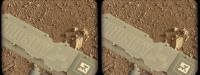
Senior Member Group: Members Posts: 1465 Joined: 9-February 04 From: Columbus OH USA Member No.: 13 |
QUOTE (Deimos @ Sep 7 2012, 08:49 PM) But you never know. Thanks... I've been working out a method to unwarp the images based on the CAHVOR camera specification for MASTCAM. Hard to say how to apply it to the cropped images though. I guess scale 1536x1152 up to 1600x1200 and then add the 48 dark columns back in. It's easier with the NAVCAM images because they at least come in at 1024x1024 as specified. I'm wondering if stitches would work a little better using such rectified images. Here's a before and after of a NAVCAM shot--it's a real subtle correction:
-------------------- |
|
|
|
|
|
|
Sep 9 2012, 07:04 PM
Post
#61
|
|
 Member Group: Members Posts: 161 Joined: 12-August 12 From: Hillsborough, NJ Member No.: 6546 |
Hey folks. I see a lot of controversy here in regards to de-bayering.
What's the story in a nutshell? Are we allowed to de-bayer them? And if so, what is the easiest and best way? I wish I knew why this was an issue. But that's probably due to my own ignorance in the matter. -------------------- |
|
|
|
|
Sep 9 2012, 07:33 PM
Post
#62
|
|
|
Senior Member Group: Members Posts: 4247 Joined: 17-January 05 Member No.: 152 |
QUOTE (iMPREPREX @ Sep 9 2012, 07:04 PM) Are we allowed to de-bayer them? Yikes! They're public, so we can deBayer them, stretch them, Philovision them, unsharp mask them, solarize them, swap R and G channels, and finally raise each pixel value to the pi'th power, if it suits us.The basic deal is that they're transmitting lossless, Bayered images, apparently for calibration purposes. We probably won't get very many of these in the future, since they take a lot of bandwidth. JPL jpegs the original images and makes them public, as they've always done. Unfortunately in this case the jpegging introduces blocky artifacts when we deBayer. If JPL deBayered them before jpegging, we wouldn't see the blocks. So we either hope that changes or wait for the full data release in six months. |
|
|
|
|
Sep 9 2012, 08:29 PM
Post
#63
|
||
|
Member Group: Members Posts: 161 Joined: 12-August 12 From: Hillsborough, NJ Member No.: 6546 |
All I have is a pattern I can't get rid of. Would look cool if it could be removed.
Attached thumbnail(s)
-------------------- |
|
|
|
|
|
|
Sep 10 2012, 05:23 AM
Post
#64
|
||
 Member Group: Members Posts: 222 Joined: 7-August 12 From: Garberville, CA Member No.: 6500 |
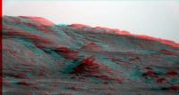
Here's a HUMONGOUS ANAGLYPH for anyone so inclined to peruse the Mt. Sharp foothills in a reasonably perceptible quantum of 3D... and surprisingly, there's some depth there!
After testing a few stitched frames out to see whether the 12 meters or so parallax difference between Sol 19 and Sol 23's color panos allowed for any 3D depth to be seen at the Mt. Sharp foothills or not I decided it warranted a BIG anaglyph just to check. Sol 19's pano has all the pictures down but unfortunately there's still 4 or 5 that have never arrived yet from from Sol 23 so there's a few missing frames in this version (the reddish areas). Now at first glance there doesn't seem to be much depth to perceive at the foothills, but zoom in a bit, and slowly pan around and sure enough... it's there alright. Seems the more you zoom in (better in the FULL version), the more evident it becomes. Sol 23 was used as left eye and Sol 19 as right. Sweet. Here's a medium sized version (6500px x 922px):
...and here's THE FULL VERSION (19738px x 2100px): http://www.edtruthan.com/mars/Sol19-and-23...-19738x2100.jpg EDIT: This image has been updated! (missing frames are down). See this post. -------------------- "We shall not cease from exploration, and the end of all our exploring will be to arrive where we started and know the place for the first time." -T.S. Eliot
|
|
|
|
|
|
|
Sep 10 2012, 05:32 PM
Post
#65
|
|
 Chief Assistant Group: Admin Posts: 1409 Joined: 5-January 05 From: Ierapetra, Greece Member No.: 136 |
woaw, very nice work..
-------------------- photographer, space imagery enthusiast, proud father and partner, and geek.
http://500px.com/sacred-photons & |
|
|
|
|
Sep 10 2012, 05:47 PM
Post
#66
|
|
|
Senior Member Group: Members Posts: 4247 Joined: 17-January 05 Member No.: 152 |
I second that. Very nicely done.
Let's hope for another M100 pan with a greater baseline to really pop out those butes and mesas... 
|
|
|
|
|
Sep 10 2012, 10:47 PM
Post
#67
|
|
|
Newbie Group: Members Posts: 17 Joined: 24-August 12 Member No.: 6610 |
The web interview with our camera operator !
http://blogs.agu.org/magmacumlaude/2012/08...onary-wedge-49/ |
|
|
|
|
Sep 11 2012, 05:26 PM
Post
#68
|
||
|
Member Group: Members Posts: 222 Joined: 7-August 12 From: Garberville, CA Member No.: 6500 |
QUOTE (fredk @ Sep 10 2012, 10:47 AM) Let's hope for another M100 pan with a greater baseline to really pop out those butes and mesas... Oh my, I agree and soon I hope! Using one of the top portions of the Sol 32 MC100 robotic arm photos as the left eye in an anaglyph test, though the horizon is frustratiingly out of focus it was enough to verify that the basline is now quite effective for imaging the base of Mt. Sharp with plenty of eye-popping depth. The test below is a little wonky to the eye because the red spectrum is so darned out of focus but it was enough to test the baseline shift's effectivness. I'd just love to do another full pan anaglyph with a new from a location somewhere well before Glenelg before it widens to much for a good Sol 19 pairing. Please give us another MC 100 full pan soon!
-------------------- "We shall not cease from exploration, and the end of all our exploring will be to arrive where we started and know the place for the first time." -T.S. Eliot
|
|
|
|
|
|
|
Sep 11 2012, 05:59 PM
Post
#69
|
|
 Administrator Group: Admin Posts: 5172 Joined: 4-August 05 From: Pasadena, CA, USA, Earth Member No.: 454 |
Oh my. I'm actually not bothered by the fuzziness of the red channel at all; those buttes pop into spectacular depth-rich focus, and the yardang material above them is surprisingly spiky.
-------------------- My website - My Patreon - @elakdawalla on Twitter - Please support unmannedspaceflight.com by donating here.
|
|
|
|
|
Sep 11 2012, 07:07 PM
Post
#70
|
|
|
Senior Member Group: Members Posts: 4247 Joined: 17-January 05 Member No.: 152 |
Now that's being resourceful! Very cool.
|
|
|
|
|
Sep 11 2012, 08:04 PM
Post
#71
|
||
|
Senior Member Group: Members Posts: 4247 Joined: 17-January 05 Member No.: 152 |
And here's my attempt at combining sol13 mastcamL (from James's mosaic) and sol32 navcam into a long baseling view. Navcam gives similar resolution to those out-of-focus mastcams, but covers a wide field. The distortions of navcam produce pretty severe headachiness at the sides of this anaglyph, so be warned:
|
|
|
|
|
|
|
Sep 11 2012, 11:31 PM
Post
#72
|
|
|
Member Group: Members Posts: 222 Joined: 7-August 12 From: Garberville, CA Member No.: 6500 |
Very Nice! I find it interesting to note how little input the brain seems to require to construct a reasonably well defined binocular portrait even with such compromised data being received from the other half of the equation. And the general baseline distance from around Bradbury to the present location are really quite nice now for rendering the depth perspectives well without too much exaggeration. Now we just need a few crisp new long shots. Will definatetly be hitting "F5" a bit more than usual...
-------------------- "We shall not cease from exploration, and the end of all our exploring will be to arrive where we started and know the place for the first time." -T.S. Eliot
|
|
|
|
|
Sep 12 2012, 07:35 PM
Post
#73
|
|
|
Junior Member Group: Members Posts: 85 Joined: 5-September 12 Member No.: 6635 |
I've been wondering if it is technically feasible to use the Mastcam Video capability to search for and record dust devil activity. Can find nothing on the board forums or the internet on this. I know they plan on doing videos of phobos eclipses so this isn't too much of a stretch.
Lets say we point the mastcam wide angle in the general direction of the dark dunes for 30 min around solar noon. The strong albedo contrast along the dune boundary would be a preferred place for dust devil development - I would guess. What are the memory/bandwith constraints in implementing something like this ? I suppose frame comparison software uploaded to the rover would be smart enough to return only video segments with changes between frames - ie dust devil/blowing dust activity. IF this makes sense so far why not make this the sort of default mode for Mastcam when it is not being used otherwise. |
|
|
|
|
Sep 12 2012, 08:30 PM
Post
#74
|
|
|
Senior Member Group: Members Posts: 2517 Joined: 13-September 05 Member No.: 497 |
QUOTE (Eyesonmars @ Sep 12 2012, 12:35 PM) I've been wondering if it is technically feasible to use the Mastcam Video capability to search for and record dust devil activity. IMHO, not really. 1) Even the 34mm Mastcam has a fairly narrow FOV (about 15 degrees.) Dust devil searching on MER was done with Navcam, see http://trs-new.jpl.nasa.gov/dspace/bitstre...8/1/08-0444.pdf 2) There's no motion detection capability in the Mastcam hardware and doing it in software would be limited to a frame rate of maybe 1/4 to 1/10 fps at best. 3) There are power limitations and running the camera all the time isn't possible. -------------------- Disclaimer: This post is based on public information only. Any opinions are my own.
|
|
|
|
|
Sep 12 2012, 09:08 PM
Post
#75
|
|
|
Junior Member Group: Members Posts: 85 Joined: 5-September 12 Member No.: 6635 |
Thanks mcaplinger for the response.
Perhaps I read too much into the list of objectives on the Mastcam website Mastcam Specs One of the bullet items under the list of objectives is: "Document atmospheric and meteorological events and processes by observing clouds, dust-raising events, properties of suspended aerosols (dust, ice crystals), and (using the video capability) eolian transport of fines" |
|
|
|
|
Sep 12 2012, 09:10 PM
Post
#76
|
|
|
Senior Member Group: Members Posts: 4247 Joined: 17-January 05 Member No.: 152 |
Maybe software could use sparsely timed images (like Spirit's DD sequences) to detect a DD with software and then trigger high frame rate video (without motion detection). But I don't know if there's much we'd learn from DD video.
It may depend on what we see - if there are lots of DDs, we'll catch some by accident. |
|
|
|
|
Sep 12 2012, 09:22 PM
Post
#77
|
|
|
Senior Member Group: Members Posts: 2517 Joined: 13-September 05 Member No.: 497 |
QUOTE (fredk @ Sep 12 2012, 02:10 PM) Maybe software could use sparsely timed images (like Spirit's DD sequences) to detect a DD with software and then trigger high frame rate video (without motion detection). Certainly it's conceivable that we could run a Navcam sequence looking for dust devils, find one, slew the Mastcam to it and start a video acquisition. That capability doesn't exist right now, though, and I don't know if the science value would be worth the effort. -------------------- Disclaimer: This post is based on public information only. Any opinions are my own.
|
|
|
|
|
Sep 12 2012, 10:02 PM
Post
#78
|
|
|
Martian Photographer Group: Members Posts: 352 Joined: 3-March 05 Member No.: 183 |
QUOTE (fredk @ Sep 12 2012, 09:10 PM) It may depend on what we see - if there are lots of DDs, we'll catch some by accident. Pathfinder, Spirit, Opportunity, and Phoenix returned their first images of dust devils serendipitously. All but Phoenix had dust devil campaigns prior to the first detection of a dust devil in an image, also. I would expect "exploratory" observations to have a different priority and implementation from "monitoring" observations. I think that with previous missions, the frequency of intentionally looking for dust devils vaguely correlates with the amount orbital evidence for dust devils in the area. M34 has some neat advantages over Navcam if you have reason to believe its FOV is sufficient--it would have been great up in the Columbia Hills--but Navcam's FOV is better for exploratory surveys, as with MER. Of course, exploration frequently follows many paths. |
|
|
|
|
Sep 13 2012, 11:50 AM
Post
#79
|
|
|
Senior Member Group: Members Posts: 2921 Joined: 14-February 06 From: Very close to the Pyrénées Mountains (France) Member No.: 682 |
I must admit there's something I don't understand.
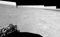
I understood that, once the covers of the Hazcam have been removed, they were to kind of hanging somewhere (I mean not on the ground). Looking at the bellypan or whatever you call it, I can't see those covers. Any thoughts? -------------------- |
|
|
|
|
Sep 13 2012, 12:32 PM
Post
#80
|
|
 Senior Member Group: Members Posts: 3419 Joined: 9-February 04 From: Minneapolis, MN, USA Member No.: 15 |
QUOTE (climber @ Sep 13 2012, 06:50 AM) I understood that, once the covers of the Hazcam have been removed, they were to kind of hanging somewhere (I mean not on the ground). Looking at the bellypan or whatever you call it, I can't see those covers. Any thoughts? If you look closely at the bellypan, underneath and offset from each of the hazcam lenses there is a spring. We know that the hazcam lens covers were designed for a one-time deployment; the springs were supposed to move them completely out of the way of the lenses, for good. My guess is that the lens covers are out of sight on the bottom of the lens housing, one each attached to each spring visible in the MAHLI images. -the other Doug -------------------- The trouble ain't that there is too many fools, but that the lightning ain't distributed right. -Mark Twain
|
|
|
|
|
Sep 13 2012, 12:38 PM
Post
#81
|
|
|
Member Group: Members Posts: 153 Joined: 4-May 11 From: Pardubice, CZ Member No.: 5979 |
QUOTE (climber @ Sep 13 2012, 01:50 PM) I must admit there's something I don't understand. I understood that, once the covers of the Hazcam have been removed, they were to kind of hanging somewhere (I mean not on the ground). Looking at the bellypan or whatever you call it, I can't see those covers. Any thoughts? This video explains it all : http://mars.jpl.nasa.gov/msl/multimedia/vi.../index.cfm?v=53 |
|
|
|
|
Sep 13 2012, 12:50 PM
Post
#82
|
||
|
Senior Member Group: Moderator Posts: 4279 Joined: 19-April 05 From: .br at .es Member No.: 253 |
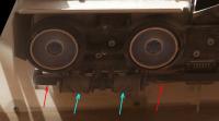
There were several posts about this topic on the landing or pre-landing thread.
You can see the springs (cyan arrows) and the covers (red arrows) on this crop image.
|
|
|
|
|
|
|
Sep 13 2012, 01:00 PM
Post
#83
|
|
 Senior Member Group: Members Posts: 2173 Joined: 28-December 04 From: Florida, USA Member No.: 132 |
QUOTE (pospa @ Sep 13 2012, 07:38 AM) This video explains it all : http://mars.jpl.nasa.gov/msl/multimedia/vi.../index.cfm?v=53 Rotating the video image shows how the cover may be hidden behind the spring.
|
|
|
|
|
Sep 13 2012, 01:52 PM
Post
#84
|
|
|
Senior Member Group: Members Posts: 2921 Joined: 14-February 06 From: Very close to the Pyrénées Mountains (France) Member No.: 682 |
Thank you ALL!
Believe me, I read ALL posts but can't remember understanding where they'll end up. Yes, spings are very evident to me for sure and I though covers have to be somewhere but I couldn't see them. Video also helps. -------------------- |
|
|
|
|
Sep 15 2012, 04:06 PM
Post
#85
|
|
 Senior Member Group: Moderator Posts: 3431 Joined: 11-August 04 From: USA Member No.: 98 |
QUOTE (fredk @ Sep 15 2012, 08:56 AM) But all of the smudginess is artifacts - the sun should be very smooth. I've noticed that they're really compressing the living daylights out of MSL images before putting them on the web - much more so than the MER images are compressed. Or are we talking about a different kind of artifacting. |
|
|
|
|
Sep 15 2012, 04:26 PM
Post
#86
|
|
 Member Group: Members Posts: 112 Joined: 20-August 12 From: Spain Member No.: 6597 |
I think the main problem behind the most artifacts is JPEG compression. I think they should try PNG or a less agressive compression scheme.
QUOTE (mhoward @ Sep 15 2012, 04:06 PM) I've noticed that they're really compressing the living daylights out of MSL images before putting them on the web - much more so than the MER images are compressed. Or are we talking about a different kind of artifacting. |
|
|
|
|
Sep 15 2012, 05:14 PM
Post
#87
|
|
|
Senior Member Group: Members Posts: 4247 Joined: 17-January 05 Member No.: 152 |
The problem with the sun image is that the public images are lossless -> jpeg rather than lossless -> debayer -> jpeg or just lossless. That's the same problem that gives the green splotches on landscape shots.
QUOTE (mhoward @ Sep 15 2012, 04:06 PM) they're really compressing the living daylights out of MSL images before putting them on the web - much more so than the MER images are compressed. I haven't noticed that - could you give an example of that? Or did you mean the bayering problem?
|
|
|
|
|
Sep 15 2012, 05:29 PM
Post
#88
|
|
|
Senior Member Group: Members Posts: 2517 Joined: 13-September 05 Member No.: 497 |
QUOTE (mhoward @ Sep 15 2012, 09:06 AM) I've noticed that they're really compressing the living daylights out of MSL images before putting them on the web... I think they're just using a fixed quality (75, maybe?). Of course it doesn't help that there is sometimes a decompress/recompress and that they JPEG-compress Bayer-pattern data. The final compression ratio seems to be around 8:1 to 9:1. Are the MER images really a lot lower compression ratio? For the 100mm sun image, since the filter cuts out all of the pixels besides blue anyway, you'd be better off just tossing the other Bayer positions and then upsampling as desired. But it's still going to be a round slightly-fuzzy circle with a bite out of one side. -------------------- Disclaimer: This post is based on public information only. Any opinions are my own.
|
|
|
|
|
Sep 15 2012, 05:35 PM
Post
#89
|
|
|
Senior Member Group: Members Posts: 3648 Joined: 1-October 05 From: Croatia Member No.: 523 |
QUOTE (mcaplinger @ Sep 15 2012, 07:29 PM) Of course it doesn't help that there is sometimes a decompress/recompress I though the cameras basically return JPEG compliant data so that there shouldn't be a need to decompress/recompress the stream again. Are they really doing that for color images? -------------------- |
|
|
|
|
Sep 15 2012, 06:03 PM
Post
#90
|
|
|
Senior Member Group: Members Posts: 2517 Joined: 13-September 05 Member No.: 497 |
QUOTE (ugordan @ Sep 15 2012, 10:35 AM) I though the cameras basically return JPEG compliant data so that there shouldn't be a need to decompress/recompress the stream again. Are they really doing that for color images? http://pds.nasa.gov/tools/policy/ExplicitP...tsStatement.pdf QUOTE PDS Archives must comply with the following All EDR image data delivered for archiving must consist of simple raster images with PDS labels Now, you could claim that this doesn't have to apply to public release images and I wouldn't argue with you, but it would require delivery in two forms unless there was a decompress/recompress cycle. -------------------- Disclaimer: This post is based on public information only. Any opinions are my own.
|
|
|
|
|
Sep 15 2012, 06:19 PM
Post
#91
|
||
|
Senior Member Group: Moderator Posts: 3431 Joined: 11-August 04 From: USA Member No.: 98 |
QUOTE (mcaplinger @ Sep 15 2012, 10:29 AM) Are the MER images really a lot lower compression ratio? I've been looking at mostly Navcam images so far, so I guess I can't and shouldn't try to say anything about Mastcam. But for MER Navcam images, the JPGs on the web usually are about 200K or more in size; MSL Navcam JPGs on the web seem to be usually around 100K or less. And there just seem to be more and stronger JPG artifacts, at least in images I've looked at of the deck. That could be factors other than compression for the web; for all I know they're being compressed more heavily on the rover in some cases. All I really know is, trying to take a MER Navcam image and make it about the same file size as the MSL Navcam images we're seeing on the web, I have to use a JPEG 'quality' setting of about 40%, which is high compression. Here's what I typically see (random section of the image that happens to be in front of me):
Attached thumbnail(s)
|
|
|
|
|
|
|
Sep 15 2012, 06:50 PM
Post
#92
|
||
|
Senior Member Group: Moderator Posts: 3431 Joined: 11-August 04 From: USA Member No.: 98 |
QUOTE (fredk @ Sep 15 2012, 10:14 AM) I haven't noticed that - could you give an example of that? Yes, an example - good idea. Again, this is Navcam; I admit the Mastcam images are probably completely different. And I don't know that this is because of heavy JPEG compression for the web. That's just my guess.
Attached thumbnail(s)
|
|
|
|
|
|
|
Sep 15 2012, 07:09 PM
Post
#93
|
|
|
Member Group: Members Posts: 282 Joined: 18-June 04 Member No.: 84 |
QUOTE (mhoward @ Sep 15 2012, 07:50 PM) Again, this is Navcam; I admit the Mastcam images are probably completely different. And I don't know that this is because of heavy JPEG compression for the web. That's just my guess. Damn.... that looks bad. |
|
|
|
|
Sep 15 2012, 07:23 PM
Post
#94
|
|
|
Senior Member Group: Members Posts: 2517 Joined: 13-September 05 Member No.: 497 |
QUOTE (mhoward @ Sep 15 2012, 11:19 AM) But for MER Navcam images, the JPGs on the web usually are about 200K or more in size; MSL Navcam JPGs on the web seem to be usually around 100K or less. Well, that speaks for itself. Assuming full 1024x1024 frames, 200K would be about 5:1 and 100K would be about 10:1. I did a quick spot check of some recent Navcams and they were more like 120K, but close enough. I don't know how they chose the JPEG quality for MER and I don't know how they chose it for MSL, but I would think that 10:1 would be about quality 50 and 5:1 would be about quality 75. My own personal opinion is that 75 would be a more appropriate choice, but nobody's asking me. As for your example, at that scale they both look pretty crummy (the MSL one has more JPEG artifacts, clearly), but I don't think zooming the image is really a fair test. That said, I wouldn't pick a fight with anyone who says the web release images are compressed too much, but I'm not sure I would use the phrase "compressing the living daylights out of" -- YMMV. -------------------- Disclaimer: This post is based on public information only. Any opinions are my own.
|
|
|
|
|
Sep 15 2012, 07:36 PM
Post
#95
|
|
|
Senior Member Group: Members Posts: 4247 Joined: 17-January 05 Member No.: 152 |
For the navcams, here's my guess. We've discussed before (image thread?) that the MSL public navcams appear to be stretched/lut'ed/delut'ed differently from the MER navcams. In practice it looks like the histograms are typically concentrated into the lower half (0-128 or so) of the full 8 bit range. So there's less information to begin with than in MER navacams. But then the details on MSL navcams tend to be dark with low contrast, so maybe jpeg doesn't capture the details as well. Then you need to stretch them to show the detail, and you end up enhancing the jpeg artifacts. You could test this by jpegging an original image, and then halving the intensity of the original, jpegging, and then doubling the intensity, and comparing the two.
Or they may be compressed more heavily on MSL. MER uses various compression levels depending on the need. |
|
|
|
|
Sep 15 2012, 07:42 PM
Post
#96
|
|
|
Senior Member Group: Members Posts: 3648 Joined: 1-October 05 From: Croatia Member No.: 523 |
QUOTE (fredk @ Sep 15 2012, 09:36 PM) Or they may be compressed more heavily on MSL. Nah, navcams use wavelet compression, but these are blocky artifacts suggesting JPEG compression on the ground is destroying data. -------------------- |
|
|
|
|
Sep 15 2012, 07:47 PM
Post
#97
|
|||
|
Senior Member Group: Moderator Posts: 3431 Joined: 11-August 04 From: USA Member No.: 98 |
QUOTE (mcaplinger @ Sep 15 2012, 12:23 PM) As for your example, at that scale they both look pretty crummy (the MSL one has more JPEG artifacts, clearly), but I don't think zooming the image is really a fair test. That said, I wouldn't pick a fight with anyone who says the web release images are compressed too much, but I'm not sure I would use the phrase "compressing the living daylights out of" -- YMMV. Fair enough. Here's a more typically-sized comparison, as good as I can make it at the moment. The MSL version still seems lossy to me. But if it is compression that's being done on the rover to get the images back faster, I'm perfectly happy with that - I'm just so happy to be seeing images at all. I only bring it up because I care. Normally I would JPEG-compress these images, but well, this is a special case for obvious reasons.
Attached thumbnail(s)
|
||
|
|
|
||
|
Sep 15 2012, 07:52 PM
Post
#98
|
|
|
Senior Member Group: Members Posts: 2517 Joined: 13-September 05 Member No.: 497 |
QUOTE (fredk @ Sep 15 2012, 12:36 PM) We've discussed before (image thread?) that the MSL public navcams appear to be stretched/lut'ed/delut'ed differently from the MER navcams. I don't about MER, but as far as I can tell there is no stretching being done on any of the MSL images. They are typically autoexposed, which by its nature might be a little on the dark side but shouldn't really need much processing. -------------------- Disclaimer: This post is based on public information only. Any opinions are my own.
|
|
|
|
|
Sep 15 2012, 08:06 PM
Post
#99
|
|
|
Senior Member Group: Members Posts: 2517 Joined: 13-September 05 Member No.: 497 |
QUOTE (mhoward @ Sep 15 2012, 12:47 PM) The MSL version still seems lossy to me. At this point I'm tempted to give into my bias and say that all Navcam images look bad to me. (Sorry, Justin. Not all, but some.)I've always been a bit surprised that the MER Navcams were so grainy-looking. This might be dark current from the relatively long readout time. They're a bit blurry but what can you do with only four elements and fixed focus? As for wavelet compression, having ICER artifacts interact with JPEG artifacts isn't going to improve the images. But to recap -- are the public release images on MSL being compressed on the ground more than for MER? Could well be. -------------------- Disclaimer: This post is based on public information only. Any opinions are my own.
|
|
|
|
|
Sep 16 2012, 06:54 AM
Post
#100
|
|
|
Junior Member Group: Members Posts: 36 Joined: 14-July 06 Member No.: 972 |
When comparing the left and right Mastcams of the sun I see a couple of things that I don't understand. The first is the large artifact at the bottom of the Mastcam 100 images. Is it a lens flare? The second is the color. The Mastcam34 thumbs are grey but the Mastcam100 thumbnails show as blue. I figured that this might have to do with the neutral density (sun) filters being different wavelengths, but looking at http://www.msss.com/msl/mastcam/MastCam_description.html the Mastcam34 sun filter is 440 nm which should be blue/violet and the Mastcam100 is 880 nm which should be near infrared. Sorry if this is obvious to others, but it seemed strange to me.
|
|
|
|
 |

|
Lo-Fi Version | Time is now: 23rd May 2024 - 04:17 AM |
|
RULES AND GUIDELINES Please read the Forum Rules and Guidelines before posting. IMAGE COPYRIGHT |
OPINIONS AND MODERATION Opinions expressed on UnmannedSpaceflight.com are those of the individual posters and do not necessarily reflect the opinions of UnmannedSpaceflight.com or The Planetary Society. The all-volunteer UnmannedSpaceflight.com moderation team is wholly independent of The Planetary Society. The Planetary Society has no influence over decisions made by the UnmannedSpaceflight.com moderators. |
SUPPORT THE FORUM Unmannedspaceflight.com is funded by the Planetary Society. Please consider supporting our work and many other projects by donating to the Society or becoming a member. |
|