MSL Post First Drive - Intermission, Start of Drive to Glenelg, Intermission between CAP 1B and 2 - Sols 17 through 29 |

MSL Post First Drive - Intermission, Start of Drive to Glenelg, Intermission between CAP 1B and 2 - Sols 17 through 29 |
 Aug 23 2012, 02:39 PM Aug 23 2012, 02:39 PM
Post
#1
|
|
 Administrator  Group: Admin Posts: 5172 Joined: 4-August 05 From: Pasadena, CA, USA, Earth Member No.: 454 |
Curiosity's Cap 1B phase was completed yesterday with the successful first drive, so now we're going into "Intermission." Dan Limonadi's guest post on the Society blog has great explanations of what all these phases mean.
QUOTE There is an “intermission” that the science team will have between CAP 1B and CAP 2. The intermission will include initial drives away from the landing site, more in-depth ChemCam and Mastcam characterization and science observations, and the first SAM atmospheric science experiment. The total length of this period depends on how long the science team wants to drive before carrying on with sample chain checkout activities. The key flavor difference of intermission is that science is more in the driver’s seat and not trying to squeeze in between higher priority engineering checkout activities that have priority during CAP 1 and 2. Our current plan is to complete a significant fraction of our drive to Glenelg during intermission Keep discussion of sol 9-16 imaging in the relevant thread -- not all of those full-frame Mastcam images are down yet.
-------------------- My website - My Patreon - @elakdawalla on Twitter - Please support unmannedspaceflight.com by donating here.
|
 |
 
|
 |
|
Aug 26 2012, 12:48 AM
Post
#2
|
|||
 Senior Member Group: Members Posts: 1465 Joined: 9-February 04 From: Columbus OH USA Member No.: 13 |
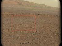
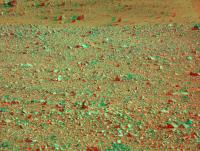
Another try at a mastcam anaglyph. Here's a smaller version of the ML image with the MR area shown by the rectangle:
The anaglyph:
-------------------- |
||
|
|
|
||
|
Aug 26 2012, 03:18 AM
Post
#3
|
|
|
Member Group: Members Posts: 252 Joined: 5-May 05 From: Mississippi (USA) Member No.: 379 |
QUOTE (jmknapp @ Aug 25 2012, 07:48 PM)  Another try at a mastcam anaglyph. Here's a smaller version of the ML image with the [url="http://mars.jpl.nasa.gov This should probably be in the Making anaglyph images, Methods and software thread but my question is did you have any further adjustments in size after cropping out the image from the larger MR area? I did somewhat the same thing*, but the objects in the ML image still appeared much smaller. It looked really weird until I started playing with something called barrel distortion in StereoPhotoMaker. I don't claim to know what I am doing but if I try enough things sometimes something works. If I don't need to correct for barrel distortion that would certainly make things simpler. * I didn't even use the full ML graphic. I finally got this. ( click below ) Comparing mine to yours - yours certainly looks cleaner. However; mine may have more 3d effect in the fore & middle ground? Yes? No? Maybe? click link: http://www.unmannedspaceflight.com/index.p...st&id=27692 http://www.unmannedspaceflight.com/index.p...st&p=189878 Jack |
|
|
|
|
Aug 26 2012, 11:41 AM
Post
#4
|
||
|
Senior Member Group: Members Posts: 1465 Joined: 9-February 04 From: Columbus OH USA Member No.: 13 |
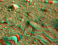
QUOTE (stewjack @ Aug 25 2012, 10:18 PM) This should probably be in the Making anaglyph images, Methods and software thread but my question is did you have any further adjustments in size after cropping out the image from the larger MR area? I did somewhat the same thing*, but the objects in the ML image still appeared much smaller. Just did it by eye in Photoshop--crop the ML, scale it up so that it matches the size of the similar area of the MR, apply level changes to RGB as appropriate, then fine tune the registration by eye using the Move tool and cursor keys until it looks about right. Lots of variables to mess up & it always seems like there are problem areas & as you say it gets a little brain-bending. But haven't tried correcting for distortions--maybe that's key. I suppose the pros use the full CAVHORE camera models to really do it right. Here's the best I can manage with one of the rover track pairs, without any geometric changes:
Looks like you might have stitched a couple of frames together? That's another complication to get right. -------------------- |
|
|
|
|
|
|
Aug 26 2012, 01:04 PM
Post
#5
|
|
|
Junior Member Group: Members Posts: 61 Joined: 5-June 05 From: 46.283N 11.433E :)) Member No.: 401 |
QUOTE (jmknapp @ Aug 26 2012, 01:41 PM) Just did it by eye in Photoshop--crop the ML, scale it up so that it matches the size of the similar area of the MR, apply level changes to RGB as appropriate, then fine tune the registration by eye using the Move tool and cursor keys until it looks about right. I don't find the two debayered frames. I would like to try my anaglyph version. Could you post the two frames? thank you |
|
|
|
|
Aug 26 2012, 04:46 PM
Post
#6
|
|
|
Senior Member Group: Members Posts: 1465 Joined: 9-February 04 From: Columbus OH USA Member No.: 13 |
QUOTE (malgar @ Aug 26 2012, 08:04 AM) I don't find the two debayered frames. I think we're on our own for debayering (demosaicing) the frames. This page has what I got anyway: http://curiositymsl.com/mcana/ The hills have those weird green patches that people are getting. It'd be interesting to see how JPL does it (Promised Land) -------------------- |
|
|
|
 elakdawalla MSL Post First Drive - Intermission, Start of Drive to Glenelg Aug 23 2012, 02:39 PM
 elakdawalla First sol 17 Navcam thumbnails are up on the raws ... Aug 23 2012, 08:03 PM fredk Could someone please de-Bayer this:
http://mars.jp... Aug 24 2012, 07:40 PM
elakdawalla First sol 17 Navcam thumbnails are up on the raws ... Aug 23 2012, 08:03 PM fredk Could someone please de-Bayer this:
http://mars.jp... Aug 24 2012, 07:40 PM
 Fred B QUOTE (fredk @ Aug 24 2012, 12:40 PM) Cou... Aug 24 2012, 07:54 PM eoincampbell QUOTE (Fred B @ Aug 24 2012, 12:54 PM) I ... Aug 24 2012, 11:34 PM Ant103 With pleasure
And with a bit more levels :
... Aug 24 2012, 07:53 PM elakdawalla Looks like a vintage postcard Really stunning.
L... Aug 24 2012, 08:07 PM Ant103 Yes Emily. And I'm wondering if Curiosity... Aug 24 2012, 08:24 PM Phil Stooke These are amazing pictures... Fred B - absolutely... Aug 24 2012, 08:27 PM akuo Wow, I think we can see there is nothing wrong wit... Aug 24 2012, 08:28 PM Phil Stooke A drive was planned for 23rd but postponed (Paolo ... Aug 25 2012, 07:18 AM RoverDriver QUOTE (Phil Stooke @ Aug 24 2012, 11:18 P... Aug 25 2012, 11:53 AM paraisosdelsistemasolar Hi to everybody,
This is my first try at converti... Aug 25 2012, 10:36 AM jmknapp That looks like the best yet!
So what is the ... Aug 25 2012, 10:59 AM ugordan QUOTE (jmknapp @ Aug 25 2012, 12:59 PM) S... Aug 25 2012, 11:56 AM paraisosdelsistemasolar Every new frame is a surprise for me. With the new... Aug 25 2012, 01:33 PM Tesheiner QUOTE (paraisosdelsistemasolar @ Aug 25 2012,... Aug 25 2012, 03:35 PM Ant103 An other unbayered image.
There is not only Pho... Aug 25 2012, 01:33 PM john_s Great images, especially the vertical panorama... Aug 25 2012, 01:58 PM ugordan QUOTE (john_s @ Aug 25 2012, 03:58 PM) Wh... Aug 25 2012, 02:18 PM paraisosdelsistemasolar It's even possible to achieve a good, but not ... Aug 25 2012, 02:51 PM elakdawalla That vertical panorama is terrific.
I have no sen... Aug 25 2012, 04:02 PM RoverDriver QUOTE (elakdawalla @ Aug 25 2012, 08:02 A... Aug 25 2012, 05:59 PM climber Also interesting to note one rock sinkage after be... Aug 25 2012, 04:24 PM Ant103 Yes, great work Parai'
My own version (full ... Aug 25 2012, 04:24 PM NickF Thanks for that great deBayering tip Ant103! H... Aug 25 2012, 04:32 PM Gladstoner . Aug 26 2012, 09:19 AM dvandorn QUOTE (Gladstoner @ Aug 26 2012, 04:19 AM... Aug 26 2012, 04:23 PM Gladstoner . Aug 26 2012, 08:48 PM djellison QUOTE (Ant103 @ Aug 25 2012, 09:24 AM) So... Aug 25 2012, 05:31 PM Stu Well, well, well... turns out Registax has a DeBay... Aug 25 2012, 05:08 PM Reckless In reply to Emily's question judging by this N... Aug 25 2012, 05:23 PM stewjack Here is my attempt at an anaglyph using ANT103... Aug 25 2012, 06:27 PM Phil Stooke I would expect that most panoramas will be just th... Aug 25 2012, 07:18 PM NickF Another deBayered stitch.
Aug 25 2012, 08:47 PM Phil Stooke Matt Heverly tweets that the next drive is ... Aug 25 2012, 09:40 PM RoverDriver We will be placing DAN on top of the northern scou... Aug 25 2012, 10:19 PM fredk My best shot at a greyscale of the mastcam 100 vie... Aug 26 2012, 12:12 AM Airbag QUOTE (jmknapp @ Aug 26 2012, 11:46 AM) I... Aug 26 2012, 06:15 PM jmknapp QUOTE (Airbag @ Aug 26 2012, 02:15 PM) Pr... Aug 27 2012, 01:37 PM mcaplinger QUOTE (jmknapp @ Aug 27 2012, 06:37 AM) I... Aug 27 2012, 02:11 PM fredk QUOTE (mcaplinger @ Aug 27 2012, 03:11 PM... Aug 27 2012, 02:36 PM mcaplinger QUOTE (fredk @ Aug 27 2012, 07:36 AM) Act... Aug 27 2012, 03:23 PM fredk QUOTE (mcaplinger @ Aug 27 2012, 04:23 PM... Aug 27 2012, 04:08 PM fredk QUOTE (jmknapp @ Aug 27 2012, 02:37 PM) p... Aug 27 2012, 02:22 PM ElkGroveDan QUOTE (fredk @ Aug 27 2012, 07:22 AM) The... Aug 27 2012, 07:44 PM ngunn QUOTE (jmknapp @ Aug 26 2012, 05:46 PM) T... Aug 26 2012, 10:41 PM Ant103 Fredk : I've took your fantastic image and app... Aug 26 2012, 01:42 AM nprev Uh...oh, my!
Wow.
The layering blows my m... Aug 26 2012, 01:58 AM dvandorn Fred -- if someone showed me your b&w image in... Aug 26 2012, 03:23 AM Pando Enhanced Fred's greyscale a bit Aug 26 2012, 05:03 AM Pando One more try to really bring out some details... I... Aug 26 2012, 05:26 AM Explorer1 Will the Mastcams still need to be formatted in th... Aug 26 2012, 07:53 AM walfy I borrowed Fred's excellent rendition to compa... Aug 26 2012, 09:21 AM paraisosdelsistemasolar It seems that during Sol 19 a relatively loose roc... Aug 26 2012, 08:56 AM Astro0 I hate to be first to say this but...
pew pew pew... Aug 26 2012, 09:04 AM paraisosdelsistemasolar I love the outcrop near to point B in the walfy pi... Aug 26 2012, 09:31 AM Phil Stooke A whole pile of new images just appeared:
http://... Aug 26 2012, 08:49 PM ngunn ChemCam is already working. A nice article from Sc... Aug 26 2012, 09:39 PM Stu QUOTE (Phil Stooke @ Aug 26 2012, 09:49 P... Aug 26 2012, 09:41 PM Phil Stooke De-bayer that!
Phil Aug 26 2012, 10:01 PM Mars3D It's been a while since I did any of these but... Aug 27 2012, 12:21 AM Brian Lynch That is a great video Mars3D, I tried finding Mars... Aug 27 2012, 12:45 AM Mars3D QUOTE (Brian Lynch @ Aug 27 2012, 01:45 A... Aug 28 2012, 09:01 PM jmknapp Ah, didn't know that the raw "bayer... Aug 27 2012, 03:02 PM Stu QUOTE (fredk @ Aug 27 2012, 05:08 PM) Whe... Aug 27 2012, 04:54 PM Phil Stooke Luxury!
Phil Aug 27 2012, 05:48 PM Eutectic Good thing we don't have to hand-color the pix... Aug 27 2012, 06:25 PM climber QUOTE (Eutectic @ Aug 27 2012, 08:25 PM) ... Aug 27 2012, 07:03 PM ElkGroveDan QUOTE (Eutectic @ Aug 27 2012, 11:25 AM) ... Aug 27 2012, 07:20 PM fredk Press conference at 2pm pacific time. Aug 27 2012, 06:43 PM Stu QUOTE (climber @ Aug 27 2012, 08:03 PM) T... Aug 27 2012, 07:22 PM john_s QUOTE (Stu @ Aug 27 2012, 12:22 PM) Actua... Aug 27 2012, 09:06 PM Josh Cryer Pic from todays briefing: http://i.imgur.com/76icp... Aug 27 2012, 09:13 PM atomoid QUOTE (Josh Cryer @ Aug 27 2012, 02:13 PM... Aug 28 2012, 02:00 AM tdemko QUOTE (atomoid @ Aug 27 2012, 08:00 PM) .... Aug 28 2012, 06:16 PM charleski From the Press conference - the animation they sho... Aug 27 2012, 09:34 PM jmknapp QUOTE (charleski @ Aug 27 2012, 05:34 PM)... Aug 28 2012, 01:20 AM Phil Stooke ... and they have now driven to a point where DAN ... Aug 27 2012, 09:40 PM Tesheiner QUOTE (Josh Cryer @ Aug 27 2012, 11:13 PM... Aug 27 2012, 10:00 PM nprev Phenomenal.
We're in the right place with the... Aug 27 2012, 10:05 PM Ant103 Sol 21 Navcam pan, in anaglyph. Classic version av... Aug 27 2012, 11:22 PM scalbers And nice at the briefing to see John Grotzinger ta... Aug 27 2012, 11:26 PM Brian Lynch Thanks, Ant, that stereo panorama looks great thro... Aug 28 2012, 12:02 AM CosmicRocker QUOTE (scalbers @ Aug 27 2012, 06:26 PM) ... Aug 28 2012, 02:51 AM Ondaweb In response to the last question about sunrise at ... Aug 28 2012, 12:46 PM fredk Pressure is low but dust is high, so scattering te... Aug 28 2012, 02:59 PM dvandorn "Whitecap" definitely shows a contact in... Aug 28 2012, 03:57 PM fredk QUOTE (dvandorn @ Aug 28 2012, 04:57 PM) ... Aug 28 2012, 09:44 PM Phil Stooke Ant's nice panorama in circular format. The t... Aug 28 2012, 04:59 PM Phil Stooke Current map - the most recent drive shape is not w... Aug 28 2012, 08:15 PM fredk Looks like a short drive on sol 22 - off to Glenel... Aug 28 2012, 09:04 PM RoverDriver QUOTE (fredk @ Aug 28 2012, 02:04 PM) Loo... Aug 28 2012, 11:30 PM akuo Excellent! We know we love drives On with the... Aug 28 2012, 09:32 PM Floyd Go Paolo! Congratulation on your first Curios... Aug 29 2012, 12:25 AM
Fred B QUOTE (fredk @ Aug 24 2012, 12:40 PM) Cou... Aug 24 2012, 07:54 PM eoincampbell QUOTE (Fred B @ Aug 24 2012, 12:54 PM) I ... Aug 24 2012, 11:34 PM Ant103 With pleasure
And with a bit more levels :
... Aug 24 2012, 07:53 PM elakdawalla Looks like a vintage postcard Really stunning.
L... Aug 24 2012, 08:07 PM Ant103 Yes Emily. And I'm wondering if Curiosity... Aug 24 2012, 08:24 PM Phil Stooke These are amazing pictures... Fred B - absolutely... Aug 24 2012, 08:27 PM akuo Wow, I think we can see there is nothing wrong wit... Aug 24 2012, 08:28 PM Phil Stooke A drive was planned for 23rd but postponed (Paolo ... Aug 25 2012, 07:18 AM RoverDriver QUOTE (Phil Stooke @ Aug 24 2012, 11:18 P... Aug 25 2012, 11:53 AM paraisosdelsistemasolar Hi to everybody,
This is my first try at converti... Aug 25 2012, 10:36 AM jmknapp That looks like the best yet!
So what is the ... Aug 25 2012, 10:59 AM ugordan QUOTE (jmknapp @ Aug 25 2012, 12:59 PM) S... Aug 25 2012, 11:56 AM paraisosdelsistemasolar Every new frame is a surprise for me. With the new... Aug 25 2012, 01:33 PM Tesheiner QUOTE (paraisosdelsistemasolar @ Aug 25 2012,... Aug 25 2012, 03:35 PM Ant103 An other unbayered image.
There is not only Pho... Aug 25 2012, 01:33 PM john_s Great images, especially the vertical panorama... Aug 25 2012, 01:58 PM ugordan QUOTE (john_s @ Aug 25 2012, 03:58 PM) Wh... Aug 25 2012, 02:18 PM paraisosdelsistemasolar It's even possible to achieve a good, but not ... Aug 25 2012, 02:51 PM elakdawalla That vertical panorama is terrific.
I have no sen... Aug 25 2012, 04:02 PM RoverDriver QUOTE (elakdawalla @ Aug 25 2012, 08:02 A... Aug 25 2012, 05:59 PM climber Also interesting to note one rock sinkage after be... Aug 25 2012, 04:24 PM Ant103 Yes, great work Parai'
My own version (full ... Aug 25 2012, 04:24 PM NickF Thanks for that great deBayering tip Ant103! H... Aug 25 2012, 04:32 PM Gladstoner . Aug 26 2012, 09:19 AM dvandorn QUOTE (Gladstoner @ Aug 26 2012, 04:19 AM... Aug 26 2012, 04:23 PM Gladstoner . Aug 26 2012, 08:48 PM djellison QUOTE (Ant103 @ Aug 25 2012, 09:24 AM) So... Aug 25 2012, 05:31 PM Stu Well, well, well... turns out Registax has a DeBay... Aug 25 2012, 05:08 PM Reckless In reply to Emily's question judging by this N... Aug 25 2012, 05:23 PM stewjack Here is my attempt at an anaglyph using ANT103... Aug 25 2012, 06:27 PM Phil Stooke I would expect that most panoramas will be just th... Aug 25 2012, 07:18 PM NickF Another deBayered stitch.
Aug 25 2012, 08:47 PM Phil Stooke Matt Heverly tweets that the next drive is ... Aug 25 2012, 09:40 PM RoverDriver We will be placing DAN on top of the northern scou... Aug 25 2012, 10:19 PM fredk My best shot at a greyscale of the mastcam 100 vie... Aug 26 2012, 12:12 AM Airbag QUOTE (jmknapp @ Aug 26 2012, 11:46 AM) I... Aug 26 2012, 06:15 PM jmknapp QUOTE (Airbag @ Aug 26 2012, 02:15 PM) Pr... Aug 27 2012, 01:37 PM mcaplinger QUOTE (jmknapp @ Aug 27 2012, 06:37 AM) I... Aug 27 2012, 02:11 PM fredk QUOTE (mcaplinger @ Aug 27 2012, 03:11 PM... Aug 27 2012, 02:36 PM mcaplinger QUOTE (fredk @ Aug 27 2012, 07:36 AM) Act... Aug 27 2012, 03:23 PM fredk QUOTE (mcaplinger @ Aug 27 2012, 04:23 PM... Aug 27 2012, 04:08 PM fredk QUOTE (jmknapp @ Aug 27 2012, 02:37 PM) p... Aug 27 2012, 02:22 PM ElkGroveDan QUOTE (fredk @ Aug 27 2012, 07:22 AM) The... Aug 27 2012, 07:44 PM ngunn QUOTE (jmknapp @ Aug 26 2012, 05:46 PM) T... Aug 26 2012, 10:41 PM Ant103 Fredk : I've took your fantastic image and app... Aug 26 2012, 01:42 AM nprev Uh...oh, my!
Wow.
The layering blows my m... Aug 26 2012, 01:58 AM dvandorn Fred -- if someone showed me your b&w image in... Aug 26 2012, 03:23 AM Pando Enhanced Fred's greyscale a bit Aug 26 2012, 05:03 AM Pando One more try to really bring out some details... I... Aug 26 2012, 05:26 AM Explorer1 Will the Mastcams still need to be formatted in th... Aug 26 2012, 07:53 AM walfy I borrowed Fred's excellent rendition to compa... Aug 26 2012, 09:21 AM paraisosdelsistemasolar It seems that during Sol 19 a relatively loose roc... Aug 26 2012, 08:56 AM Astro0 I hate to be first to say this but...
pew pew pew... Aug 26 2012, 09:04 AM paraisosdelsistemasolar I love the outcrop near to point B in the walfy pi... Aug 26 2012, 09:31 AM Phil Stooke A whole pile of new images just appeared:
http://... Aug 26 2012, 08:49 PM ngunn ChemCam is already working. A nice article from Sc... Aug 26 2012, 09:39 PM Stu QUOTE (Phil Stooke @ Aug 26 2012, 09:49 P... Aug 26 2012, 09:41 PM Phil Stooke De-bayer that!
Phil Aug 26 2012, 10:01 PM Mars3D It's been a while since I did any of these but... Aug 27 2012, 12:21 AM Brian Lynch That is a great video Mars3D, I tried finding Mars... Aug 27 2012, 12:45 AM Mars3D QUOTE (Brian Lynch @ Aug 27 2012, 01:45 A... Aug 28 2012, 09:01 PM jmknapp Ah, didn't know that the raw "bayer... Aug 27 2012, 03:02 PM Stu QUOTE (fredk @ Aug 27 2012, 05:08 PM) Whe... Aug 27 2012, 04:54 PM Phil Stooke Luxury!
Phil Aug 27 2012, 05:48 PM Eutectic Good thing we don't have to hand-color the pix... Aug 27 2012, 06:25 PM climber QUOTE (Eutectic @ Aug 27 2012, 08:25 PM) ... Aug 27 2012, 07:03 PM ElkGroveDan QUOTE (Eutectic @ Aug 27 2012, 11:25 AM) ... Aug 27 2012, 07:20 PM fredk Press conference at 2pm pacific time. Aug 27 2012, 06:43 PM Stu QUOTE (climber @ Aug 27 2012, 08:03 PM) T... Aug 27 2012, 07:22 PM john_s QUOTE (Stu @ Aug 27 2012, 12:22 PM) Actua... Aug 27 2012, 09:06 PM Josh Cryer Pic from todays briefing: http://i.imgur.com/76icp... Aug 27 2012, 09:13 PM atomoid QUOTE (Josh Cryer @ Aug 27 2012, 02:13 PM... Aug 28 2012, 02:00 AM tdemko QUOTE (atomoid @ Aug 27 2012, 08:00 PM) .... Aug 28 2012, 06:16 PM charleski From the Press conference - the animation they sho... Aug 27 2012, 09:34 PM jmknapp QUOTE (charleski @ Aug 27 2012, 05:34 PM)... Aug 28 2012, 01:20 AM Phil Stooke ... and they have now driven to a point where DAN ... Aug 27 2012, 09:40 PM Tesheiner QUOTE (Josh Cryer @ Aug 27 2012, 11:13 PM... Aug 27 2012, 10:00 PM nprev Phenomenal.
We're in the right place with the... Aug 27 2012, 10:05 PM Ant103 Sol 21 Navcam pan, in anaglyph. Classic version av... Aug 27 2012, 11:22 PM scalbers And nice at the briefing to see John Grotzinger ta... Aug 27 2012, 11:26 PM Brian Lynch Thanks, Ant, that stereo panorama looks great thro... Aug 28 2012, 12:02 AM CosmicRocker QUOTE (scalbers @ Aug 27 2012, 06:26 PM) ... Aug 28 2012, 02:51 AM Ondaweb In response to the last question about sunrise at ... Aug 28 2012, 12:46 PM fredk Pressure is low but dust is high, so scattering te... Aug 28 2012, 02:59 PM dvandorn "Whitecap" definitely shows a contact in... Aug 28 2012, 03:57 PM fredk QUOTE (dvandorn @ Aug 28 2012, 04:57 PM) ... Aug 28 2012, 09:44 PM Phil Stooke Ant's nice panorama in circular format. The t... Aug 28 2012, 04:59 PM Phil Stooke Current map - the most recent drive shape is not w... Aug 28 2012, 08:15 PM fredk Looks like a short drive on sol 22 - off to Glenel... Aug 28 2012, 09:04 PM RoverDriver QUOTE (fredk @ Aug 28 2012, 02:04 PM) Loo... Aug 28 2012, 11:30 PM akuo Excellent! We know we love drives On with the... Aug 28 2012, 09:32 PM Floyd Go Paolo! Congratulation on your first Curios... Aug 29 2012, 12:25 AM |

|
Lo-Fi Version | Time is now: 28th May 2024 - 11:52 PM |
|
RULES AND GUIDELINES Please read the Forum Rules and Guidelines before posting. IMAGE COPYRIGHT |
OPINIONS AND MODERATION Opinions expressed on UnmannedSpaceflight.com are those of the individual posters and do not necessarily reflect the opinions of UnmannedSpaceflight.com or The Planetary Society. The all-volunteer UnmannedSpaceflight.com moderation team is wholly independent of The Planetary Society. The Planetary Society has no influence over decisions made by the UnmannedSpaceflight.com moderators. |
SUPPORT THE FORUM Unmannedspaceflight.com is funded by the Planetary Society. Please consider supporting our work and many other projects by donating to the Society or becoming a member. |
|