Viking '75 Mars Lander Construction, Looking for Viking lander design/construction information |

Viking '75 Mars Lander Construction, Looking for Viking lander design/construction information |
 May 17 2012, 12:38 AM May 17 2012, 12:38 AM
Post
#1
|
|
 Member  Group: Members Posts: 101 Joined: 3-May 12 From: Massachusetts, USA Member No.: 6392 |
Greetings all! I am searching for detailed construction and design information about the NASA Viking '75 Mars project hardware, particularly for the lander, aeroshell, base cover, and bioshield. Can anyone recommend good sources? I am especially looking for engineering drawings and under-construction photographs.
To set the stage, here is an album of about 100 drawings and photos which I've collected so far. I have already read the "usual" books, such as NASA RP-1027 "Viking '75 Spacecraft Design and Test", the press kits, the scientific papers produced about the mission, a number of industry papers covering various instruments and subsystems, the major Martin Marietta books, etc. I am hoping to find additional sources. Any ideas? Also, does anyone know if there are aeroshell, base cover, or bioshield components lurking in a museum or in storage somewhere? FYI, I have visited three of the best landers still on Earth: The Proof Test Capsule in the Smithsonian NASM, the Flight Capsule 3 (backup) in the Museum of Flight near Seattle, and the Science Test Lander in the Virginia Air and Space Center. I've taken nearly 1,000 photos of the three of them (most of which are publicly available in other Picasa Web albums of mine). I've taken a few measurements, but I would dearly love to find more authoritative drawings of more hardware (interior, exterior, everything). I have begun submitting some Freedom of Information Act requests to NASA/JPL which has started to bear some trivial but kind of fun fruit. --- Update as of March 2017: During the past few years I have been fortunate enough to collect a significant amount of information on the Viking lander hardware. My thanks to a number of organizations for providing me access to their resources:
Flight Capsule 3 in Seattle Museum of Flight (756 photos) Dimensioned diagrams of the FC3 lander PTC Lander at Smithsonian NASM 2013 (466 photos) PTC Lander at Smithsonian NASM 2016 (888 photos) Lander at Virginia Air and Space Center (622 photos) Dimensioned diagrams of the VASCs lander Lander at California Science Center (456 photos) Dimensioned diagrams of the CSC's lander Misc diagrams, unusual photos (over 350 images) Body assembly blueprints Collector Head Shroud Unit at NASA LaRC (99 photos) Biology instrument at Cleveland MoNH (36 photos) Meteorology Sensor Assembly (60 photos) Meteorology Electronics Assembly (22 photos) Tape Recorder (53 photos) High Gain Antenna photos and measurements (96 images) XRFS Instrument (42 images) Viking lander contractor historic scale model (14 images) My Viking project documents collection The main focus of my efforts during the past few years has been to create an accurate and high-fidelity digital 3D model of the Viking lander. I've chosen to use the SketchUp software to build the model because a near-full-featured free version is available, allowing other people to use my model. The 3D model itself, as a work-in-progress, is available via DropBox. I update that model file periodically as major elements get added. I've created an album containing numerous renderings of digital model components, and I have a YouTube channel with some videos about the modeling project. I have also uploaded the lander core body and the Surface Sampler Collector Head to the SketchUp 3D Warehouse so that other people can easily access those components (the 3D Warehouse can be accessed from within SketchUp, or via web browser). The file on DropBox lister earlier contains those components and others. -- Tom |
 |
 
|
 |
|
Aug 17 2013, 06:44 PM
Post
#2
|
||
|
Member Group: Members Posts: 101 Joined: 3-May 12 From: Massachusetts, USA Member No.: 6392 |
Thanks to the extremely kind assistance and cooperation from the staff at the California Science Center I have been able to take detailed measurements and photographs of the Viking lander on display at the CSC. I owe a huge debt of gratitude to David Gansen, Frank Hernandez, and Ken Phillips of the CSC senior staff for facilitating my recent visit -- thank you gentlemen!
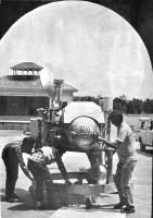
My album of photographs is now available, with captions. Also available is an album of dimensioned diagrams totaling over 300 individual measurements. I used a variety of tools to capture the measurements, principally a high-quality 6-inch dial caliper and 12-inch outside caliper. Longer or hard-to-reach features were measured with a small tape measure (with ability to directly measure diameters). Angular measurements were made with a digital angle gauge. Profiles were captured with a multi-tooth plastic contour gauge. Broad curves were captured with flexible curve templates. A few part outlines were directly traced on paper. There was discussion earlier in this thread regarding the origin of the lander displayed at the CSC. Last year I had reservations regarding its authenticity based on its numerous mock-up components and the listing of this apparent unit on the Penwal Prototypes Signature Projects web site. Over a year ago I had written to Penwal asking about their involvement, but never received a reply. The CSC staff does not have much information regarding the nature of this lander. I have not been able to contact Lockheed Martin, who loaned the unit to the CSC. Then a couple of months ago I found and purchased a vintage 1981 Denver Post press photo which appears to show the same lander:
The original press caption with that image identifies some Martin Marietta employees who were installing the unit for display at the Denver Pavilion of Science Technology in May 1981. Unusual features matching the CSC's lander include the roll control thrusters (on fuel tank 2) mounted upside down; odd main fuel line routing; and not-quite Flight design of the High Gain Antenna (HGA) mast, drive head, and dish. In addition upon close inspection of the CSC's lander I observed numerous original Martin Marietta part and serial number stencils on lander components. Camera 1 is an authentic Itek lander camera (serial number 0001 according to its data stencil). All of this evidence convinces me now that the lander displayed at the California Science Center is one of the four test units created by Martin Marietta. It is nevertheless true that various external components are clear mock-ups, including the Meteorology Boom Assembly; camera 2; the Inertial Reference Unit; the Radar Altimeter Electronics and Lander Pyrotechnic Control Assemblies; and the Valve Drive Amplifier (some of which are constructed of wood). Further trivia: leg 3's primary strut differs slightly from the final design; the three Terminal Descent Engines are Rocket Research Company original units, with TDE 1's gold housing featuring a slight variation (square cut-out for the throttle valve). I had an extremely enjoyable day at the California Science Center, and hope to return in the future (there is much more work to do). Thanks again to David, Frank, and Ken for your hospitality and help! |
|
|
|
|
|
 Tom Dahl Viking '75 Mars Lander Construction May 17 2012, 12:38 AM
 tasp Can't remember where I read this, but at least... May 17 2012, 12:32 PM Tom Dahl I have begun creating a 3D model of the Viking lan... Jun 21 2012, 02:40 AM Tom Dahl I am looking for a good-quality version of an imag... Jul 9 2012, 02:06 AM djellison There is a model - I'm not sure of its fidelit... Aug 29 2012, 03:41 AM nprev IIRC, they've got the actual ground engineerin... Aug 29 2012, 09:38 AM Tom Dahl Hi Doug -- regarding the California Science Center... Aug 29 2012, 12:46 PM Tom Dahl In September had the opportunity to spend a couple... Nov 12 2012, 06:11 PM Tom Dahl A few months ago I was delighted to acquire a vint... Jun 7 2013, 03:57 PM Tom Dahl Here is a progress report on my 3D digital model o... Jun 23 2014, 02:43 AM elakdawalla Nice work, and thanks for sharing the SketchUp fil... Jun 23 2014, 03:17 PM Tom Dahl Update on my project to create a 3D digital model ... Nov 23 2014, 04:17 AM
 PaulH51 QUOTE (Tom Dahl @ Nov 23 2014, 12:17 PM) ... Nov 23 2014, 05:47 AM vikingmars QUOTE (Tom Dahl @ Nov 23 2014, 05:17 AM) ... Nov 23 2014, 09:22 AM
 Tom Dahl Today's update on my digital 3D SketchUp model... Aug 31 2015, 02:12 AM vikingmars QUOTE (Tom Dahl @ Aug 31 2015, 04:12 AM) ... Aug 31 2015, 07:57 AM droidtoaster Amazing Tom, thanks!
When I was at the CSC I ... Nov 24 2014, 12:35 AM Tom Dahl Here is some additional information on Viking land... Dec 21 2014, 09:17 PM pospa QUOTE (Tom Dahl @ Dec 21 2014, 11:17 PM) ... Jun 17 2015, 12:30 PM Mr Valiant Tom,
Your in depth examination of the Viking Land... Jun 18 2015, 12:17 AM Tom Dahl My on-going quest to research the Viking '75 m... Jun 17 2015, 12:47 AM monty python Wow Tom. Thanks much for the video. It gives me in... Aug 31 2015, 03:46 AM bear10829 In case you don't know about this particular t... Sep 4 2015, 09:27 AM Tom Dahl Hi bear10829, that is indeed a wonderful archive. ... Sep 4 2015, 02:17 PM RachelVL3 Tom,
Your progress is astounding and it is a plea... Nov 1 2015, 04:09 PM Tom Dahl Thank you Rachel, I appreciate the compliment and ... Nov 1 2015, 04:30 PM Tom Dahl I just completed a new video animation of my work-... Jan 16 2016, 02:15 PM Tom Tamlyn QUOTE (Tom Dahl @ Jan 16 2016, 10:15 AM) ... Jun 7 2016, 05:53 AM Tom Dahl My main goal is to model essentially all exterior ... Jun 7 2016, 11:42 PM Tom Dahl On May 20 I visited the Smithsonian National Air a... Jun 6 2016, 11:48 PM Tom Dahl I recently completed a 12-minute making-of video t... Aug 7 2016, 01:18 PM Tom Dahl This past weekend I completed a 3D digital model (... Nov 22 2016, 01:11 AM Tom Dahl I've completed modeling the hardware that moun... Dec 24 2016, 04:30 PM rlorenz QUOTE (Tom Dahl @ Dec 24 2016, 11:30 AM) ... Dec 25 2016, 03:58 PM Tom Dahl Making progress on the Surface Sampler Acquisition... Mar 28 2017, 02:53 PM djellison As someone who has dabbled in various 3D platforms... Mar 28 2017, 03:44 PM Tom Dahl Thank you for the compliment, Doug! It's a... Mar 29 2017, 11:24 PM djellison Yeah - structure from motion can struggle with fla... Mar 30 2017, 05:51 PM Tom Dahl Thanks for pointing out dead links. I have edited ... Mar 30 2017, 11:31 PM Tom Dahl During the past few weeks I've added the front... May 20 2017, 03:54 PM Tom Dahl Here are close-ups of the pedestal base and yoke g... May 20 2017, 03:59 PM Tom Dahl Next up are the components of the boom extend-retr... Jun 27 2017, 12:01 AM PaulH51 QUOTE (Tom Dahl @ Jun 27 2017, 08:01 AM) ... Jun 27 2017, 09:45 AM monty python Thanks. Always wondered how that worked. Jun 28 2017, 05:31 AM Tom Dahl The Viking lander's Surface Sampler Acquisitio... Aug 4 2017, 04:14 PM Tom Dahl I've completed a detailed (nearly 18 minutes l... Jan 14 2018, 12:37 AM vikingmars QUOTE (Tom Dahl @ Jan 14 2018, 01:37 AM) ... Jan 14 2018, 08:37 AM monty python Tom, that is fantastic! I am old enough to rem... Jan 14 2018, 09:14 AM Floyd Tom, thank you for a fantastic movie. It is visua... Jan 14 2018, 03:24 PM john_s Beautiful engineering, beautifully rendered and pr... Jan 26 2018, 09:23 PM PFK As a humble chemist (albeit one who vividly rememb... Jan 27 2018, 11:44 AM Tom Dahl The next chapter in the effort to create a high-fi... Jan 9 2019, 12:51 AM PaulH51 QUOTE (Tom Dahl @ Jan 9 2019, 08:51 AM) T... Jan 9 2019, 01:31 AM sittingduck Tom, what you're doing is not only historical ... Jan 9 2019, 03:41 PM Tom Dahl I've completed the remaining two communication... Oct 3 2019, 02:12 AM scalbers Nice to see these antennas again. I especially rec... Oct 3 2019, 09:56 PM mcaplinger Over on nasawatch it's being claimed that the ... Apr 2 2020, 07:46 PM climber QUOTE (mcaplinger @ Apr 2 2020, 08:46 PM)... Apr 2 2020, 08:49 PM atomoid its already April 2nd, so what the heck is the NAS... Apr 2 2020, 10:13 PM Tom Dahl As far as I know, the NASA "worm" logo d... Apr 2 2020, 10:57 PM Tom Dahl I have completed a 22-minute video that describes ... Jul 8 2020, 12:02 PM Tom Dahl The latest addition to my work-in-progress Viking ... Apr 18 2021, 02:42 AM Tom Dahl Here are detailed views of the MR-50F roll-control... Apr 18 2021, 02:53 AM Tom Dahl Here are details of the pair of main valves on eac... Apr 18 2021, 03:08 AM Tom Dahl I have been adding some major internal components ... Oct 23 2021, 12:38 AM vikingmars QUOTE (Tom Dahl @ Oct 23 2021, 02:38 AM) ... Oct 25 2021, 10:02 PM Tom Dahl The next Viking lander component 3D models to be c... May 19 2022, 10:39 PM scalbers Here are a few recent photos of the spare flight q... Jan 2 2023, 07:43 PM Tom Dahl Indeed the Flight Capsule 3 or FC3/VL3 backup land... Jan 3 2023, 12:31 AM BYEMAN Just wondering if anybody has come across a docume... Jan 3 2023, 12:48 AM Tom Dahl QUOTE (BYEMAN @ Jan 2 2023, 07:48 PM) Jus... Jan 4 2023, 02:46 AM Tom Dahl I have recently completed modeling the Viking land... Jun 7 2023, 12:55 PM Floyd Thank you Tom. The models and writeup are outstan... Jun 7 2023, 02:43 PM mcaplinger Great post on the RTGs, Tom! Looking forward ... Jun 7 2023, 03:37 PM Tom Dahl Indeed it surely was pretty hot within the lander... Jun 7 2023, 11:08 PM rlorenz QUOTE (Tom Dahl @ Jun 7 2023, 06:08 PM) .... Jul 22 2023, 01:02 AM Tom Dahl I have completed integrating the SNAP-19 Viking RT... Jul 15 2023, 06:57 PM Tom Dahl Here are exploded views of the wind cover for RTG ... Jul 15 2023, 07:48 PM Tom Dahl Here are renderings of the entire RTG installation... Jul 15 2023, 07:51 PM Tom Dahl Lastly (for now!) here is an overall view of t... Jul 15 2023, 07:56 PM Tom Dahl I just completed a 21-minute video describing the ... Dec 27 2023, 11:35 PM vikingmars QUOTE (Tom Dahl @ Dec 28 2023, 12:35 AM) ... Dec 28 2023, 12:58 PM john_s Second that- wonderful and amazing stuff, and I le... Dec 28 2023, 03:12 PM Glevesque QUOTE (Tom Dahl @ Dec 27 2023, 06:35 PM) ... Dec 30 2023, 05:28 PM
Tom Dahl Today's update on my digital 3D SketchUp model... Aug 31 2015, 02:12 AM vikingmars QUOTE (Tom Dahl @ Aug 31 2015, 04:12 AM) ... Aug 31 2015, 07:57 AM droidtoaster Amazing Tom, thanks!
When I was at the CSC I ... Nov 24 2014, 12:35 AM Tom Dahl Here is some additional information on Viking land... Dec 21 2014, 09:17 PM pospa QUOTE (Tom Dahl @ Dec 21 2014, 11:17 PM) ... Jun 17 2015, 12:30 PM Mr Valiant Tom,
Your in depth examination of the Viking Land... Jun 18 2015, 12:17 AM Tom Dahl My on-going quest to research the Viking '75 m... Jun 17 2015, 12:47 AM monty python Wow Tom. Thanks much for the video. It gives me in... Aug 31 2015, 03:46 AM bear10829 In case you don't know about this particular t... Sep 4 2015, 09:27 AM Tom Dahl Hi bear10829, that is indeed a wonderful archive. ... Sep 4 2015, 02:17 PM RachelVL3 Tom,
Your progress is astounding and it is a plea... Nov 1 2015, 04:09 PM Tom Dahl Thank you Rachel, I appreciate the compliment and ... Nov 1 2015, 04:30 PM Tom Dahl I just completed a new video animation of my work-... Jan 16 2016, 02:15 PM Tom Tamlyn QUOTE (Tom Dahl @ Jan 16 2016, 10:15 AM) ... Jun 7 2016, 05:53 AM Tom Dahl My main goal is to model essentially all exterior ... Jun 7 2016, 11:42 PM Tom Dahl On May 20 I visited the Smithsonian National Air a... Jun 6 2016, 11:48 PM Tom Dahl I recently completed a 12-minute making-of video t... Aug 7 2016, 01:18 PM Tom Dahl This past weekend I completed a 3D digital model (... Nov 22 2016, 01:11 AM Tom Dahl I've completed modeling the hardware that moun... Dec 24 2016, 04:30 PM rlorenz QUOTE (Tom Dahl @ Dec 24 2016, 11:30 AM) ... Dec 25 2016, 03:58 PM Tom Dahl Making progress on the Surface Sampler Acquisition... Mar 28 2017, 02:53 PM djellison As someone who has dabbled in various 3D platforms... Mar 28 2017, 03:44 PM Tom Dahl Thank you for the compliment, Doug! It's a... Mar 29 2017, 11:24 PM djellison Yeah - structure from motion can struggle with fla... Mar 30 2017, 05:51 PM Tom Dahl Thanks for pointing out dead links. I have edited ... Mar 30 2017, 11:31 PM Tom Dahl During the past few weeks I've added the front... May 20 2017, 03:54 PM Tom Dahl Here are close-ups of the pedestal base and yoke g... May 20 2017, 03:59 PM Tom Dahl Next up are the components of the boom extend-retr... Jun 27 2017, 12:01 AM PaulH51 QUOTE (Tom Dahl @ Jun 27 2017, 08:01 AM) ... Jun 27 2017, 09:45 AM monty python Thanks. Always wondered how that worked. Jun 28 2017, 05:31 AM Tom Dahl The Viking lander's Surface Sampler Acquisitio... Aug 4 2017, 04:14 PM Tom Dahl I've completed a detailed (nearly 18 minutes l... Jan 14 2018, 12:37 AM vikingmars QUOTE (Tom Dahl @ Jan 14 2018, 01:37 AM) ... Jan 14 2018, 08:37 AM monty python Tom, that is fantastic! I am old enough to rem... Jan 14 2018, 09:14 AM Floyd Tom, thank you for a fantastic movie. It is visua... Jan 14 2018, 03:24 PM john_s Beautiful engineering, beautifully rendered and pr... Jan 26 2018, 09:23 PM PFK As a humble chemist (albeit one who vividly rememb... Jan 27 2018, 11:44 AM Tom Dahl The next chapter in the effort to create a high-fi... Jan 9 2019, 12:51 AM PaulH51 QUOTE (Tom Dahl @ Jan 9 2019, 08:51 AM) T... Jan 9 2019, 01:31 AM sittingduck Tom, what you're doing is not only historical ... Jan 9 2019, 03:41 PM Tom Dahl I've completed the remaining two communication... Oct 3 2019, 02:12 AM scalbers Nice to see these antennas again. I especially rec... Oct 3 2019, 09:56 PM mcaplinger Over on nasawatch it's being claimed that the ... Apr 2 2020, 07:46 PM climber QUOTE (mcaplinger @ Apr 2 2020, 08:46 PM)... Apr 2 2020, 08:49 PM atomoid its already April 2nd, so what the heck is the NAS... Apr 2 2020, 10:13 PM Tom Dahl As far as I know, the NASA "worm" logo d... Apr 2 2020, 10:57 PM Tom Dahl I have completed a 22-minute video that describes ... Jul 8 2020, 12:02 PM Tom Dahl The latest addition to my work-in-progress Viking ... Apr 18 2021, 02:42 AM Tom Dahl Here are detailed views of the MR-50F roll-control... Apr 18 2021, 02:53 AM Tom Dahl Here are details of the pair of main valves on eac... Apr 18 2021, 03:08 AM Tom Dahl I have been adding some major internal components ... Oct 23 2021, 12:38 AM vikingmars QUOTE (Tom Dahl @ Oct 23 2021, 02:38 AM) ... Oct 25 2021, 10:02 PM Tom Dahl The next Viking lander component 3D models to be c... May 19 2022, 10:39 PM scalbers Here are a few recent photos of the spare flight q... Jan 2 2023, 07:43 PM Tom Dahl Indeed the Flight Capsule 3 or FC3/VL3 backup land... Jan 3 2023, 12:31 AM BYEMAN Just wondering if anybody has come across a docume... Jan 3 2023, 12:48 AM Tom Dahl QUOTE (BYEMAN @ Jan 2 2023, 07:48 PM) Jus... Jan 4 2023, 02:46 AM Tom Dahl I have recently completed modeling the Viking land... Jun 7 2023, 12:55 PM Floyd Thank you Tom. The models and writeup are outstan... Jun 7 2023, 02:43 PM mcaplinger Great post on the RTGs, Tom! Looking forward ... Jun 7 2023, 03:37 PM Tom Dahl Indeed it surely was pretty hot within the lander... Jun 7 2023, 11:08 PM rlorenz QUOTE (Tom Dahl @ Jun 7 2023, 06:08 PM) .... Jul 22 2023, 01:02 AM Tom Dahl I have completed integrating the SNAP-19 Viking RT... Jul 15 2023, 06:57 PM Tom Dahl Here are exploded views of the wind cover for RTG ... Jul 15 2023, 07:48 PM Tom Dahl Here are renderings of the entire RTG installation... Jul 15 2023, 07:51 PM Tom Dahl Lastly (for now!) here is an overall view of t... Jul 15 2023, 07:56 PM Tom Dahl I just completed a 21-minute video describing the ... Dec 27 2023, 11:35 PM vikingmars QUOTE (Tom Dahl @ Dec 28 2023, 12:35 AM) ... Dec 28 2023, 12:58 PM john_s Second that- wonderful and amazing stuff, and I le... Dec 28 2023, 03:12 PM Glevesque QUOTE (Tom Dahl @ Dec 27 2023, 06:35 PM) ... Dec 30 2023, 05:28 PM |

|
Lo-Fi Version | Time is now: 21st September 2024 - 10:19 PM |
|
RULES AND GUIDELINES Please read the Forum Rules and Guidelines before posting. IMAGE COPYRIGHT |
OPINIONS AND MODERATION Opinions expressed on UnmannedSpaceflight.com are those of the individual posters and do not necessarily reflect the opinions of UnmannedSpaceflight.com or The Planetary Society. The all-volunteer UnmannedSpaceflight.com moderation team is wholly independent of The Planetary Society. The Planetary Society has no influence over decisions made by the UnmannedSpaceflight.com moderators. |
SUPPORT THE FORUM Unmannedspaceflight.com is funded by the Planetary Society. Please consider supporting our work and many other projects by donating to the Society or becoming a member. |
|