Mars 3 (Various Topics Merged) |

Mars 3 (Various Topics Merged) |
 Dec 29 2004, 10:36 PM Dec 29 2004, 10:36 PM
Post
#211
|
|
 Interplanetary Dumpster Diver  Group: Admin Posts: 4404 Joined: 17-February 04 From: Powell, TN Member No.: 33 |
On my website sometime back, I added a page on the image fragment sent back by the Mars-3 Lander. I released serveral versions, including the best quality processing using othodox techniques I would use on other images plus colorization here:
http://pages.preferred.com/%7Etedstryk/fragmentc.jpg However, I released another image, which I called a "What if" image. This image can be seen here http://pages.preferred.com/%7Etedstryk/m3s5b.jpg It was produced via extreme processing of the original data to make a Mars-like scene, but I made it clear on my website it was only a speculative image. I strongly doubt if the raw data even shows Mars at all - it could be all noise. But since this mode of processing looked strangely Viking-like, I figured I would put it on the web. I was warned by several, who said that while fun, some kooks might take it seriously. My response was that I really don't care what kooks think. Then I noticed this web page: http://en.wikipedia.org/wiki/Mars_2 They used the overprocessed image. I feel like it is being presented as a true photograph. This is of concern. -------------------- |
 |
 
|
 |
| Guest_alex_k_* |
Oct 21 2014, 05:34 AM
Post
#212
|
|
Guests |
Without noised 3rd layer we get also appropriate composition.
[attachment=34051:m416_2.png] QUOTE (4th rock from the sun @ Oct 20 2014, 09:46 PM)  But both images are hard to reconcile indeed. Here's what the same processing brings out on the teleprinter image: [attachment=34042:teleprinter2.png] I suppose that it was build using wrong assumptions but very strong noise reduction, that's why it's so hard to reconcile it. I think it was made of fragments 2+4 but they were combined in wrong order. |
|
|
|
|
Oct 21 2014, 02:29 PM
Post
#213
|
|
|
Member Group: Members Posts: 378 Joined: 21-April 05 From: Portugal Member No.: 347 |
Alex, can't really disagree (and I don't read russian, so my understanding of the sources is limited), but I think your results have too many "ifs".
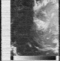
If there are several fragments, if the fragments show the same data, if one of the fragments is inverted, etc, etc. So let's stay on the things we know. We know that the image starts with the autogain system gradually increases the gain up to a "standard" level. Therefore any fragments that don't show that have no image data. You have a point with the image not being a negative, since it's possible that the initial level was too high and the autogain has reduced the level and it's also possible that the "3" area is the mirror flyback. It's reasonable to consider that values during the flyback would be zero (but who know if they didn't insert a white signal for calibration + alignment? ) So as an alternative solution we get something like this:  The area "3" does seem like the end/start of each line, I've place it at top here just to be clear. But beyond the negative/positive possibilities I don't think we should speculate much. -------------------- _______________________
www.astrosurf.com/nunes |
|
|
|
| Guest_alex_k_* |
Oct 21 2014, 03:42 PM
Post
#214
|
|
Guests |
QUOTE (4th rock from the sun @ Oct 21 2014, 07:29 PM) Alex, can't really disagree (and I don't read russian, so my understanding of the sources is limited), but I think your results have too many "ifs". If there are several fragments, if the fragments show the same data, if one of the fragments is inverted, etc, etc. It's true, there're many "ifs". But the accordance of the fragments I can try to prove. QUOTE (4th rock from the sun @ Oct 21 2014, 07:29 PM) We know that the image starts with the autogain system gradually increases the gain up to a "standard" level. Therefore any fragments that don't show that have no image data. We know only that it's Selivanov's explaination. Can you show me the effect of "gradually increase" on a panorama of Luna-9 or Luna-13? QUOTE (4th rock from the sun @ Oct 21 2014, 07:29 PM) The area "3" does seem like the end/start of each line, You're right. So the areas "4" and "2" should be combined, but not by just omitting the area "2", but by swapping them ("end" and "start" should end and start the entire line). I suppose that the same error was made in the processing of the picture "from a teleprinter". If we remount it we'll get a kind of compliance with my image. |
|
|
|
|
Oct 21 2014, 04:51 PM
Post
#215
|
||
|
Member Group: Members Posts: 378 Joined: 21-April 05 From: Portugal Member No.: 347 |
"We know only that it's Selivanov's explaination. Can you show me the effect of "gradually increase" on a panorama of Luna-9 or Luna-13?"
I can't. But I haven't seen the raw data* from the Lunas, only the final panoramas  How do you explain it if it's not the autogain system? - Mirror flyback? - Grayscale calibration at the start of each line? - Autogain of the orbiter's receiver ? For the sake of discussion, let me present a modern HF-Fax analog image:
This is what an analog image transmission looks like. Its single side band AM with the image data encoded as image tones varying from black at 1500 Hz and peak white at 2300 Hz. Some black/white or grayscale calibration elements are usually present . We know from Luna 9 that the Soviet system was similar. Don't know if some raw data exists for that, but perhaps it might help to clarify things. * This information from Jodrell Bank about Luna 9 is helpful: " The international facsimile standard is that the White/black transition corresponds to a a change in audio frequency between 1.5 to 2.3 kHz, while the Luna 9 transmissions used a change from 1.2 to 2.0 kHz. The difference in horizontal/vertical ratio was sometimes given as a factor 2 and sometimes as a factor 2.5 . The picture signals were transmitted on a subcarrier with maximum deviation of 2 kHz. The synchronization signal for the pictures (start of each line?) was a tone with the frequency 1.1 kHz (24). The lunar panoramas consisted of vertical lines with 500 elements (each 3.6 minutes of arc wide) and the 360 degree view around the horizon consisted of 6000 such lines" (from http://www.jb.man.ac.uk/history/tracking/part2.html) -------------------- _______________________
www.astrosurf.com/nunes |
|
|
|
|
|
 tedstryk Mars 3 (Various Topics Merged) Dec 29 2004, 10:36 PM
 alex_k 2. Fragments 2+4, rotated 180 deg.
3. Fragments... Oct 21 2014, 05:26 AM Bjorn Jonsson It would be interesting to reprocess this using mo... Oct 21 2014, 08:23 PM nprev Bjorn's points are valid, particularly the fac... Oct 22 2014, 12:29 AM alex_k
Here is an attempt to get 12x superresolution of ... Jan 3 2015, 04:24 PM alex_k [del]
ADMIN NOTE: Attempting to get an image and ... Jan 4 2015, 07:45 AM alex_k [del] Dec 2 2016, 11:17 AM
alex_k 2. Fragments 2+4, rotated 180 deg.
3. Fragments... Oct 21 2014, 05:26 AM Bjorn Jonsson It would be interesting to reprocess this using mo... Oct 21 2014, 08:23 PM nprev Bjorn's points are valid, particularly the fac... Oct 22 2014, 12:29 AM alex_k
Here is an attempt to get 12x superresolution of ... Jan 3 2015, 04:24 PM alex_k [del]
ADMIN NOTE: Attempting to get an image and ... Jan 4 2015, 07:45 AM alex_k [del] Dec 2 2016, 11:17 AM alex_k A recent article about processing Mars 3 signals (... Mar 18 2024, 05:09 AM
 |

|
Lo-Fi Version | Time is now: 8th June 2024 - 11:47 PM |
|
RULES AND GUIDELINES Please read the Forum Rules and Guidelines before posting. IMAGE COPYRIGHT |
OPINIONS AND MODERATION Opinions expressed on UnmannedSpaceflight.com are those of the individual posters and do not necessarily reflect the opinions of UnmannedSpaceflight.com or The Planetary Society. The all-volunteer UnmannedSpaceflight.com moderation team is wholly independent of The Planetary Society. The Planetary Society has no influence over decisions made by the UnmannedSpaceflight.com moderators. |
SUPPORT THE FORUM Unmannedspaceflight.com is funded by the Planetary Society. Please consider supporting our work and many other projects by donating to the Society or becoming a member. |
|