Viking '75 Mars Lander Construction, Looking for Viking lander design/construction information |

Viking '75 Mars Lander Construction, Looking for Viking lander design/construction information |
 May 17 2012, 12:38 AM May 17 2012, 12:38 AM
Post
#1
|
|
 Member  Group: Members Posts: 101 Joined: 3-May 12 From: Massachusetts, USA Member No.: 6392 |
Greetings all! I am searching for detailed construction and design information about the NASA Viking '75 Mars project hardware, particularly for the lander, aeroshell, base cover, and bioshield. Can anyone recommend good sources? I am especially looking for engineering drawings and under-construction photographs.
To set the stage, here is an album of about 100 drawings and photos which I've collected so far. I have already read the "usual" books, such as NASA RP-1027 "Viking '75 Spacecraft Design and Test", the press kits, the scientific papers produced about the mission, a number of industry papers covering various instruments and subsystems, the major Martin Marietta books, etc. I am hoping to find additional sources. Any ideas? Also, does anyone know if there are aeroshell, base cover, or bioshield components lurking in a museum or in storage somewhere? FYI, I have visited three of the best landers still on Earth: The Proof Test Capsule in the Smithsonian NASM, the Flight Capsule 3 (backup) in the Museum of Flight near Seattle, and the Science Test Lander in the Virginia Air and Space Center. I've taken nearly 1,000 photos of the three of them (most of which are publicly available in other Picasa Web albums of mine). I've taken a few measurements, but I would dearly love to find more authoritative drawings of more hardware (interior, exterior, everything). I have begun submitting some Freedom of Information Act requests to NASA/JPL which has started to bear some trivial but kind of fun fruit. --- Update as of March 2017: During the past few years I have been fortunate enough to collect a significant amount of information on the Viking lander hardware. My thanks to a number of organizations for providing me access to their resources:
Flight Capsule 3 in Seattle Museum of Flight (756 photos) Dimensioned diagrams of the FC3 lander PTC Lander at Smithsonian NASM 2013 (466 photos) PTC Lander at Smithsonian NASM 2016 (888 photos) Lander at Virginia Air and Space Center (622 photos) Dimensioned diagrams of the VASCs lander Lander at California Science Center (456 photos) Dimensioned diagrams of the CSC's lander Misc diagrams, unusual photos (over 350 images) Body assembly blueprints Collector Head Shroud Unit at NASA LaRC (99 photos) Biology instrument at Cleveland MoNH (36 photos) Meteorology Sensor Assembly (60 photos) Meteorology Electronics Assembly (22 photos) Tape Recorder (53 photos) High Gain Antenna photos and measurements (96 images) XRFS Instrument (42 images) Viking lander contractor historic scale model (14 images) My Viking project documents collection The main focus of my efforts during the past few years has been to create an accurate and high-fidelity digital 3D model of the Viking lander. I've chosen to use the SketchUp software to build the model because a near-full-featured free version is available, allowing other people to use my model. The 3D model itself, as a work-in-progress, is available via DropBox. I update that model file periodically as major elements get added. I've created an album containing numerous renderings of digital model components, and I have a YouTube channel with some videos about the modeling project. I have also uploaded the lander core body and the Surface Sampler Collector Head to the SketchUp 3D Warehouse so that other people can easily access those components (the 3D Warehouse can be accessed from within SketchUp, or via web browser). The file on DropBox lister earlier contains those components and others. -- Tom |
 |
 
|
 |
|
May 19 2022, 10:39 PM
Post
#2
|
||||||||
|
Member Group: Members Posts: 101 Joined: 3-May 12 From: Massachusetts, USA Member No.: 6392 |
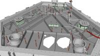
The next Viking lander component 3D models to be completed represent the lander's two thermal switches, which were mounted on the upper surface of the lander's Equipment Plate (the subject of my prior post above). The thermal switches are seen here as green-tinted boxy objects (the contactor assembly) connected to horizontal cylinders (the actuator assembly), on the left and right sides of the rendering. The green coloration represents the fact that I don't have exact measurements for these components.
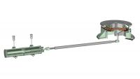
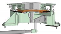
The purpose of each thermal switch was to permit and regulate the transfer of heat from the Radioisotope Thermoelectric Generator (RTG, not shown) mounted directly above the switch contactor assembly, into the lander interior. The near-surface atmospheric temperature of Mars, as measured by the Viking landers, varied from about 1F during a summer day to -178F during a winter night. Most of the lander's components, including electronics and especially its rechargeable batteries, would not survive well-below-freezing temperatures. The RTG's housing exterior was at a fairly steady temperature of about 330F (thanks to the natural radioactive decay of plutonium contained in the RTG's internal fuel capsule), and the lander was designed to utilize that heat to maintain adequate internal temperatures. During cold periods the thermal switch actuator would close the thermal switch, forming a thermally-conductive path between the bottom of the RTG and the lander's internal Equipment Plate. During relatively warm periods, the actuator would open the switch, interrupting the high-conductivity path and allowing relatively little heat to flow into the lander. When the RTGs were installed onto the landers prior to launch, Earth's relatively dense sea-level atmosphere provided an excess of available heating during the final months prior to launch. Even with the thermal switches open, there was too much heating. Therefore, a coolant loop was incorporated into the lander which circulated chilled water through End Cap Coolers mounted on top of and below each RTG. The top side of the thermal switch contactor assembly was hard-bolted to the underside of the corresponding RTG's lower End Cap Cooler. The bottom of the contactor assembly was hard-bolted to a platform machined into the Equipment Plate. Here is a cut-away view of a thermal switch with actuator assembly on the left and contactor assembly on the right, connected via a linkage that transmitted the horizontal movement of a piston within the actuator to the contactor.
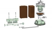
Here is an exploded view of a thermal switch. The brown objects in two stacks at center are 0.001 inch thick copper foils, 100 per stack. These foils are the core of the conductive path. In the assembled thermal switch, the stacks are interleaved forming a 200-foil group (visible in the middle of the exploded contactor on the right). The foils are bonded together where they overlap at center, and also at their ends, forming a cross with short flexible arms.
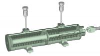
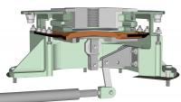
Here is a close-up of the cut-away actuator assembly. Freon gas filled the volume surrounding the two bellows chambers. When warmed, the freon expanded and pushed the central piston to the right. The piston pushed the linkage rod which connects the actuator to the contactor via clevises at both linkage ends.
Here are close-up cut-away views of the contactor assembly, first showing the closed configuration and then as opened. The central area of the stack of copper flexible foils is moved up (when closed) and down (when open) via a bellcrank driven from the actuator assembly by the linkage rod. A layer of highly-conductive tin is cast on top of the foil stack. When the switch is closed, the tin "seat" presses hard against the underside of a very thick block called the platten (at top-center of the images, with a vertical thread hole). The platten is hard bolted to the lower End Cap Cooler, upon which is mounted the hot RTG housing itself. Heat from the RTG flows downward through the lower End Cap Cooler, the platten, the tin seat, and into the center of the stack of copper foils. The heat then flows sideways through the flexible foil arms and into the boxy lower base (tinted green, across the center of the image) of the contactor assembly. Because the base is hard-bolted to the Equipment Plate, heat flows into the plate and spreads throughout the upper part of the lander interior. The lander's internal temperature-sensitive components (computer, batteries etc.) are bolted to the underside of that plate and therefore receive heat. When the switch is opened the central portion of the stack of copper foils moves downward, causing the tin seat to pull away from the bottom of the platten. While the platten remains permanently warm (as the RTG's plutonium fuel slowly decays over decades), relatively little heat is radiated from the platten to the seat and foils. The switch provides an effective 50:1 heat conductance ratio when closed vs. opened.
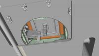
Lastly, here is an view of the underside of a thermal switch when mounted on the Equipment Plate.
|
|||||||
|
|
|
|||||||
 Tom Dahl Viking '75 Mars Lander Construction May 17 2012, 12:38 AM
 tasp Can't remember where I read this, but at least... May 17 2012, 12:32 PM Tom Dahl I have begun creating a 3D model of the Viking lan... Jun 21 2012, 02:40 AM Tom Dahl I am looking for a good-quality version of an imag... Jul 9 2012, 02:06 AM djellison There is a model - I'm not sure of its fidelit... Aug 29 2012, 03:41 AM nprev IIRC, they've got the actual ground engineerin... Aug 29 2012, 09:38 AM Tom Dahl Hi Doug -- regarding the California Science Center... Aug 29 2012, 12:46 PM Tom Dahl In September had the opportunity to spend a couple... Nov 12 2012, 06:11 PM Tom Dahl A few months ago I was delighted to acquire a vint... Jun 7 2013, 03:57 PM Tom Dahl Thanks to the extremely kind assistance and cooper... Aug 17 2013, 06:44 PM Tom Dahl Here is a progress report on my 3D digital model o... Jun 23 2014, 02:43 AM elakdawalla Nice work, and thanks for sharing the SketchUp fil... Jun 23 2014, 03:17 PM Tom Dahl Update on my project to create a 3D digital model ... Nov 23 2014, 04:17 AM
 PaulH51 QUOTE (Tom Dahl @ Nov 23 2014, 12:17 PM) ... Nov 23 2014, 05:47 AM vikingmars QUOTE (Tom Dahl @ Nov 23 2014, 05:17 AM) ... Nov 23 2014, 09:22 AM
 Tom Dahl Today's update on my digital 3D SketchUp model... Aug 31 2015, 02:12 AM vikingmars QUOTE (Tom Dahl @ Aug 31 2015, 04:12 AM) ... Aug 31 2015, 07:57 AM droidtoaster Amazing Tom, thanks!
When I was at the CSC I ... Nov 24 2014, 12:35 AM Tom Dahl Here is some additional information on Viking land... Dec 21 2014, 09:17 PM pospa QUOTE (Tom Dahl @ Dec 21 2014, 11:17 PM) ... Jun 17 2015, 12:30 PM Mr Valiant Tom,
Your in depth examination of the Viking Land... Jun 18 2015, 12:17 AM Tom Dahl My on-going quest to research the Viking '75 m... Jun 17 2015, 12:47 AM monty python Wow Tom. Thanks much for the video. It gives me in... Aug 31 2015, 03:46 AM bear10829 In case you don't know about this particular t... Sep 4 2015, 09:27 AM Tom Dahl Hi bear10829, that is indeed a wonderful archive. ... Sep 4 2015, 02:17 PM RachelVL3 Tom,
Your progress is astounding and it is a plea... Nov 1 2015, 04:09 PM Tom Dahl Thank you Rachel, I appreciate the compliment and ... Nov 1 2015, 04:30 PM Tom Dahl I just completed a new video animation of my work-... Jan 16 2016, 02:15 PM Tom Tamlyn QUOTE (Tom Dahl @ Jan 16 2016, 10:15 AM) ... Jun 7 2016, 05:53 AM Tom Dahl My main goal is to model essentially all exterior ... Jun 7 2016, 11:42 PM Tom Dahl On May 20 I visited the Smithsonian National Air a... Jun 6 2016, 11:48 PM Tom Dahl I recently completed a 12-minute making-of video t... Aug 7 2016, 01:18 PM Tom Dahl This past weekend I completed a 3D digital model (... Nov 22 2016, 01:11 AM Tom Dahl I've completed modeling the hardware that moun... Dec 24 2016, 04:30 PM rlorenz QUOTE (Tom Dahl @ Dec 24 2016, 11:30 AM) ... Dec 25 2016, 03:58 PM Tom Dahl Making progress on the Surface Sampler Acquisition... Mar 28 2017, 02:53 PM djellison As someone who has dabbled in various 3D platforms... Mar 28 2017, 03:44 PM Tom Dahl Thank you for the compliment, Doug! It's a... Mar 29 2017, 11:24 PM djellison Yeah - structure from motion can struggle with fla... Mar 30 2017, 05:51 PM Tom Dahl Thanks for pointing out dead links. I have edited ... Mar 30 2017, 11:31 PM Tom Dahl During the past few weeks I've added the front... May 20 2017, 03:54 PM Tom Dahl Here are close-ups of the pedestal base and yoke g... May 20 2017, 03:59 PM Tom Dahl Next up are the components of the boom extend-retr... Jun 27 2017, 12:01 AM PaulH51 QUOTE (Tom Dahl @ Jun 27 2017, 08:01 AM) ... Jun 27 2017, 09:45 AM monty python Thanks. Always wondered how that worked. Jun 28 2017, 05:31 AM Tom Dahl The Viking lander's Surface Sampler Acquisitio... Aug 4 2017, 04:14 PM Tom Dahl I've completed a detailed (nearly 18 minutes l... Jan 14 2018, 12:37 AM vikingmars QUOTE (Tom Dahl @ Jan 14 2018, 01:37 AM) ... Jan 14 2018, 08:37 AM monty python Tom, that is fantastic! I am old enough to rem... Jan 14 2018, 09:14 AM Floyd Tom, thank you for a fantastic movie. It is visua... Jan 14 2018, 03:24 PM john_s Beautiful engineering, beautifully rendered and pr... Jan 26 2018, 09:23 PM PFK As a humble chemist (albeit one who vividly rememb... Jan 27 2018, 11:44 AM Tom Dahl The next chapter in the effort to create a high-fi... Jan 9 2019, 12:51 AM PaulH51 QUOTE (Tom Dahl @ Jan 9 2019, 08:51 AM) T... Jan 9 2019, 01:31 AM sittingduck Tom, what you're doing is not only historical ... Jan 9 2019, 03:41 PM Tom Dahl I've completed the remaining two communication... Oct 3 2019, 02:12 AM scalbers Nice to see these antennas again. I especially rec... Oct 3 2019, 09:56 PM mcaplinger Over on nasawatch it's being claimed that the ... Apr 2 2020, 07:46 PM climber QUOTE (mcaplinger @ Apr 2 2020, 08:46 PM)... Apr 2 2020, 08:49 PM atomoid its already April 2nd, so what the heck is the NAS... Apr 2 2020, 10:13 PM Tom Dahl As far as I know, the NASA "worm" logo d... Apr 2 2020, 10:57 PM Tom Dahl I have completed a 22-minute video that describes ... Jul 8 2020, 12:02 PM Tom Dahl The latest addition to my work-in-progress Viking ... Apr 18 2021, 02:42 AM Tom Dahl Here are detailed views of the MR-50F roll-control... Apr 18 2021, 02:53 AM Tom Dahl Here are details of the pair of main valves on eac... Apr 18 2021, 03:08 AM Tom Dahl I have been adding some major internal components ... Oct 23 2021, 12:38 AM vikingmars QUOTE (Tom Dahl @ Oct 23 2021, 02:38 AM) ... Oct 25 2021, 10:02 PM scalbers Here are a few recent photos of the spare flight q... Jan 2 2023, 07:43 PM Tom Dahl Indeed the Flight Capsule 3 or FC3/VL3 backup land... Jan 3 2023, 12:31 AM BYEMAN Just wondering if anybody has come across a docume... Jan 3 2023, 12:48 AM Tom Dahl QUOTE (BYEMAN @ Jan 2 2023, 07:48 PM) Jus... Jan 4 2023, 02:46 AM Tom Dahl I have recently completed modeling the Viking land... Jun 7 2023, 12:55 PM Floyd Thank you Tom. The models and writeup are outstan... Jun 7 2023, 02:43 PM mcaplinger Great post on the RTGs, Tom! Looking forward ... Jun 7 2023, 03:37 PM Tom Dahl Indeed it surely was pretty hot within the lander... Jun 7 2023, 11:08 PM rlorenz QUOTE (Tom Dahl @ Jun 7 2023, 06:08 PM) .... Jul 22 2023, 01:02 AM Tom Dahl I have completed integrating the SNAP-19 Viking RT... Jul 15 2023, 06:57 PM Tom Dahl Here are exploded views of the wind cover for RTG ... Jul 15 2023, 07:48 PM Tom Dahl Here are renderings of the entire RTG installation... Jul 15 2023, 07:51 PM Tom Dahl Lastly (for now!) here is an overall view of t... Jul 15 2023, 07:56 PM Tom Dahl I just completed a 21-minute video describing the ... Dec 27 2023, 11:35 PM vikingmars QUOTE (Tom Dahl @ Dec 28 2023, 12:35 AM) ... Dec 28 2023, 12:58 PM john_s Second that- wonderful and amazing stuff, and I le... Dec 28 2023, 03:12 PM Glevesque QUOTE (Tom Dahl @ Dec 27 2023, 06:35 PM) ... Dec 30 2023, 05:28 PM
Tom Dahl Today's update on my digital 3D SketchUp model... Aug 31 2015, 02:12 AM vikingmars QUOTE (Tom Dahl @ Aug 31 2015, 04:12 AM) ... Aug 31 2015, 07:57 AM droidtoaster Amazing Tom, thanks!
When I was at the CSC I ... Nov 24 2014, 12:35 AM Tom Dahl Here is some additional information on Viking land... Dec 21 2014, 09:17 PM pospa QUOTE (Tom Dahl @ Dec 21 2014, 11:17 PM) ... Jun 17 2015, 12:30 PM Mr Valiant Tom,
Your in depth examination of the Viking Land... Jun 18 2015, 12:17 AM Tom Dahl My on-going quest to research the Viking '75 m... Jun 17 2015, 12:47 AM monty python Wow Tom. Thanks much for the video. It gives me in... Aug 31 2015, 03:46 AM bear10829 In case you don't know about this particular t... Sep 4 2015, 09:27 AM Tom Dahl Hi bear10829, that is indeed a wonderful archive. ... Sep 4 2015, 02:17 PM RachelVL3 Tom,
Your progress is astounding and it is a plea... Nov 1 2015, 04:09 PM Tom Dahl Thank you Rachel, I appreciate the compliment and ... Nov 1 2015, 04:30 PM Tom Dahl I just completed a new video animation of my work-... Jan 16 2016, 02:15 PM Tom Tamlyn QUOTE (Tom Dahl @ Jan 16 2016, 10:15 AM) ... Jun 7 2016, 05:53 AM Tom Dahl My main goal is to model essentially all exterior ... Jun 7 2016, 11:42 PM Tom Dahl On May 20 I visited the Smithsonian National Air a... Jun 6 2016, 11:48 PM Tom Dahl I recently completed a 12-minute making-of video t... Aug 7 2016, 01:18 PM Tom Dahl This past weekend I completed a 3D digital model (... Nov 22 2016, 01:11 AM Tom Dahl I've completed modeling the hardware that moun... Dec 24 2016, 04:30 PM rlorenz QUOTE (Tom Dahl @ Dec 24 2016, 11:30 AM) ... Dec 25 2016, 03:58 PM Tom Dahl Making progress on the Surface Sampler Acquisition... Mar 28 2017, 02:53 PM djellison As someone who has dabbled in various 3D platforms... Mar 28 2017, 03:44 PM Tom Dahl Thank you for the compliment, Doug! It's a... Mar 29 2017, 11:24 PM djellison Yeah - structure from motion can struggle with fla... Mar 30 2017, 05:51 PM Tom Dahl Thanks for pointing out dead links. I have edited ... Mar 30 2017, 11:31 PM Tom Dahl During the past few weeks I've added the front... May 20 2017, 03:54 PM Tom Dahl Here are close-ups of the pedestal base and yoke g... May 20 2017, 03:59 PM Tom Dahl Next up are the components of the boom extend-retr... Jun 27 2017, 12:01 AM PaulH51 QUOTE (Tom Dahl @ Jun 27 2017, 08:01 AM) ... Jun 27 2017, 09:45 AM monty python Thanks. Always wondered how that worked. Jun 28 2017, 05:31 AM Tom Dahl The Viking lander's Surface Sampler Acquisitio... Aug 4 2017, 04:14 PM Tom Dahl I've completed a detailed (nearly 18 minutes l... Jan 14 2018, 12:37 AM vikingmars QUOTE (Tom Dahl @ Jan 14 2018, 01:37 AM) ... Jan 14 2018, 08:37 AM monty python Tom, that is fantastic! I am old enough to rem... Jan 14 2018, 09:14 AM Floyd Tom, thank you for a fantastic movie. It is visua... Jan 14 2018, 03:24 PM john_s Beautiful engineering, beautifully rendered and pr... Jan 26 2018, 09:23 PM PFK As a humble chemist (albeit one who vividly rememb... Jan 27 2018, 11:44 AM Tom Dahl The next chapter in the effort to create a high-fi... Jan 9 2019, 12:51 AM PaulH51 QUOTE (Tom Dahl @ Jan 9 2019, 08:51 AM) T... Jan 9 2019, 01:31 AM sittingduck Tom, what you're doing is not only historical ... Jan 9 2019, 03:41 PM Tom Dahl I've completed the remaining two communication... Oct 3 2019, 02:12 AM scalbers Nice to see these antennas again. I especially rec... Oct 3 2019, 09:56 PM mcaplinger Over on nasawatch it's being claimed that the ... Apr 2 2020, 07:46 PM climber QUOTE (mcaplinger @ Apr 2 2020, 08:46 PM)... Apr 2 2020, 08:49 PM atomoid its already April 2nd, so what the heck is the NAS... Apr 2 2020, 10:13 PM Tom Dahl As far as I know, the NASA "worm" logo d... Apr 2 2020, 10:57 PM Tom Dahl I have completed a 22-minute video that describes ... Jul 8 2020, 12:02 PM Tom Dahl The latest addition to my work-in-progress Viking ... Apr 18 2021, 02:42 AM Tom Dahl Here are detailed views of the MR-50F roll-control... Apr 18 2021, 02:53 AM Tom Dahl Here are details of the pair of main valves on eac... Apr 18 2021, 03:08 AM Tom Dahl I have been adding some major internal components ... Oct 23 2021, 12:38 AM vikingmars QUOTE (Tom Dahl @ Oct 23 2021, 02:38 AM) ... Oct 25 2021, 10:02 PM scalbers Here are a few recent photos of the spare flight q... Jan 2 2023, 07:43 PM Tom Dahl Indeed the Flight Capsule 3 or FC3/VL3 backup land... Jan 3 2023, 12:31 AM BYEMAN Just wondering if anybody has come across a docume... Jan 3 2023, 12:48 AM Tom Dahl QUOTE (BYEMAN @ Jan 2 2023, 07:48 PM) Jus... Jan 4 2023, 02:46 AM Tom Dahl I have recently completed modeling the Viking land... Jun 7 2023, 12:55 PM Floyd Thank you Tom. The models and writeup are outstan... Jun 7 2023, 02:43 PM mcaplinger Great post on the RTGs, Tom! Looking forward ... Jun 7 2023, 03:37 PM Tom Dahl Indeed it surely was pretty hot within the lander... Jun 7 2023, 11:08 PM rlorenz QUOTE (Tom Dahl @ Jun 7 2023, 06:08 PM) .... Jul 22 2023, 01:02 AM Tom Dahl I have completed integrating the SNAP-19 Viking RT... Jul 15 2023, 06:57 PM Tom Dahl Here are exploded views of the wind cover for RTG ... Jul 15 2023, 07:48 PM Tom Dahl Here are renderings of the entire RTG installation... Jul 15 2023, 07:51 PM Tom Dahl Lastly (for now!) here is an overall view of t... Jul 15 2023, 07:56 PM Tom Dahl I just completed a 21-minute video describing the ... Dec 27 2023, 11:35 PM vikingmars QUOTE (Tom Dahl @ Dec 28 2023, 12:35 AM) ... Dec 28 2023, 12:58 PM john_s Second that- wonderful and amazing stuff, and I le... Dec 28 2023, 03:12 PM Glevesque QUOTE (Tom Dahl @ Dec 27 2023, 06:35 PM) ... Dec 30 2023, 05:28 PM |

|
Lo-Fi Version | Time is now: 26th May 2024 - 12:36 AM |
|
RULES AND GUIDELINES Please read the Forum Rules and Guidelines before posting. IMAGE COPYRIGHT |
OPINIONS AND MODERATION Opinions expressed on UnmannedSpaceflight.com are those of the individual posters and do not necessarily reflect the opinions of UnmannedSpaceflight.com or The Planetary Society. The all-volunteer UnmannedSpaceflight.com moderation team is wholly independent of The Planetary Society. The Planetary Society has no influence over decisions made by the UnmannedSpaceflight.com moderators. |
SUPPORT THE FORUM Unmannedspaceflight.com is funded by the Planetary Society. Please consider supporting our work and many other projects by donating to the Society or becoming a member. |
|