Chandrayaan 2 TMC 3D modelling |

Chandrayaan 2 TMC 3D modelling |
 Jan 8 2023, 08:55 AM Jan 8 2023, 08:55 AM
Post
#1
|
|||
|
Junior Member  Group: Members Posts: 55 Joined: 23-July 11 Member No.: 6083 |
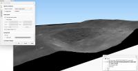
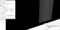
I have a question about constructing 3D models using the latest TMC data. I've tried using QGIS (and also Blender) to generate them using the DTM-OTH pairs available, and it seems that the only way a sensible looking model can be geneated is by reducing the Z axuis exaggeration by something like 0.00025. I'm using the QGIS2threejs plugin, and that multiplication value is pure guesswork based on "what looks right".
Does anyone have an explanation as to why the original geotiffs have such a huge vertical displacement, or a way of working out what the exact value should be? Attached are images showig the original and adjusted values for a pass covering the Descartes region.
|
||
 |
 
|
||

 John Moore There is some information concerning this 2012 pap... Jan 10 2023, 11:02 PM
 JohnVV i do not use qgis all that much , but use Blender ... Jan 11 2023, 03:38 PM
  |

|
Lo-Fi Version | Time is now: 23rd September 2024 - 08:56 AM |
|
RULES AND GUIDELINES Please read the Forum Rules and Guidelines before posting. IMAGE COPYRIGHT |
OPINIONS AND MODERATION Opinions expressed on UnmannedSpaceflight.com are those of the individual posters and do not necessarily reflect the opinions of UnmannedSpaceflight.com or The Planetary Society. The all-volunteer UnmannedSpaceflight.com moderation team is wholly independent of The Planetary Society. The Planetary Society has no influence over decisions made by the UnmannedSpaceflight.com moderators. |
SUPPORT THE FORUM Unmannedspaceflight.com is funded by the Planetary Society. Please consider supporting our work and many other projects by donating to the Society or becoming a member. |
|