Viking '75 Mars Lander Construction, Looking for Viking lander design/construction information |

Viking '75 Mars Lander Construction, Looking for Viking lander design/construction information |
 May 17 2012, 12:38 AM May 17 2012, 12:38 AM
Post
#1
|
|
 Member  Group: Members Posts: 101 Joined: 3-May 12 From: Massachusetts, USA Member No.: 6392 |
Greetings all! I am searching for detailed construction and design information about the NASA Viking '75 Mars project hardware, particularly for the lander, aeroshell, base cover, and bioshield. Can anyone recommend good sources? I am especially looking for engineering drawings and under-construction photographs.
To set the stage, here is an album of about 100 drawings and photos which I've collected so far. I have already read the "usual" books, such as NASA RP-1027 "Viking '75 Spacecraft Design and Test", the press kits, the scientific papers produced about the mission, a number of industry papers covering various instruments and subsystems, the major Martin Marietta books, etc. I am hoping to find additional sources. Any ideas? Also, does anyone know if there are aeroshell, base cover, or bioshield components lurking in a museum or in storage somewhere? FYI, I have visited three of the best landers still on Earth: The Proof Test Capsule in the Smithsonian NASM, the Flight Capsule 3 (backup) in the Museum of Flight near Seattle, and the Science Test Lander in the Virginia Air and Space Center. I've taken nearly 1,000 photos of the three of them (most of which are publicly available in other Picasa Web albums of mine). I've taken a few measurements, but I would dearly love to find more authoritative drawings of more hardware (interior, exterior, everything). I have begun submitting some Freedom of Information Act requests to NASA/JPL which has started to bear some trivial but kind of fun fruit. --- Update as of March 2017: During the past few years I have been fortunate enough to collect a significant amount of information on the Viking lander hardware. My thanks to a number of organizations for providing me access to their resources:
Flight Capsule 3 in Seattle Museum of Flight (756 photos) Dimensioned diagrams of the FC3 lander PTC Lander at Smithsonian NASM 2013 (466 photos) PTC Lander at Smithsonian NASM 2016 (888 photos) Lander at Virginia Air and Space Center (622 photos) Dimensioned diagrams of the VASCs lander Lander at California Science Center (456 photos) Dimensioned diagrams of the CSC's lander Misc diagrams, unusual photos (over 350 images) Body assembly blueprints Collector Head Shroud Unit at NASA LaRC (99 photos) Biology instrument at Cleveland MoNH (36 photos) Meteorology Sensor Assembly (60 photos) Meteorology Electronics Assembly (22 photos) Tape Recorder (53 photos) High Gain Antenna photos and measurements (96 images) XRFS Instrument (42 images) Viking lander contractor historic scale model (14 images) My Viking project documents collection The main focus of my efforts during the past few years has been to create an accurate and high-fidelity digital 3D model of the Viking lander. I've chosen to use the SketchUp software to build the model because a near-full-featured free version is available, allowing other people to use my model. The 3D model itself, as a work-in-progress, is available via DropBox. I update that model file periodically as major elements get added. I've created an album containing numerous renderings of digital model components, and I have a YouTube channel with some videos about the modeling project. I have also uploaded the lander core body and the Surface Sampler Collector Head to the SketchUp 3D Warehouse so that other people can easily access those components (the 3D Warehouse can be accessed from within SketchUp, or via web browser). The file on DropBox lister earlier contains those components and others. -- Tom |
 |
 
|
 |
|
Jun 7 2023, 12:55 PM
Post
#2
|
||||||||||
|
Member Group: Members Posts: 101 Joined: 3-May 12 From: Massachusetts, USA Member No.: 6392 |
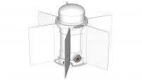
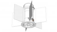
I have recently completed modeling the Viking landers two Radioisotope Thermoelectric Generators (RTGs). Here are some overall views:
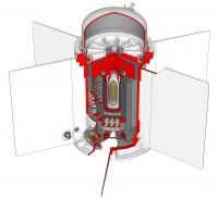
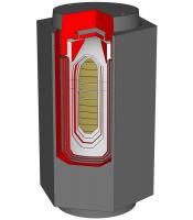
Here is an overall cut-away view of the RTG:
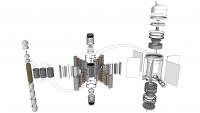
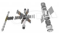
The RTGs are a Viking-specific variant of the SNAP-19 type which was used on earlier spacecraft (Nimbus III, Pioneer 10 and 11). SNAP is an acronym for System for Nuclear Auxiliary Power, which is a series of generators stretching back to the 1950s. Odd-numbered SNAP designs convert the heat of natural radioisotopic decay directly into electricity. Even-numbered designs contain a nuclear reactor in which a radioisotope undergoes accelerated nuclear fission; the resulting heat is converted into electricity in a variety of means. The Viking SNAP-19 RTGs were fueled with Plutonium 238 in the form of Plutonium Dioxide Cermet (rather than the more hazardous pure Plutonium 238 metal), which is 83% PuO2 and 17% Molybdenum. The fuel was shaped into 18 discs or pucks, seen on the far left in the following exploded views:
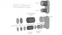
The RTG has no moving parts and is completely passive with no means of control. It weighs about 34 pounds and is a bit over 15 inches high (including the dome on top). The span of the six cooling fins is 23 inches across opposite pairs. There are 20,600 curies of fuel (equivalent to a few pounds) sufficient to generate 682 thermal watts from the heat of natural radioactive decay at the time of fueling (which was some nine months prior to launch). At the beginning of the mission the RTG produced about 42 watts of electricity at 4.4 volts DC. The conversion is quite inefficient but the generator has extreme reliability and robustness, and the excess heat was critical to the mission (heating the landers interior electronic components). Electricity is generated via the thermoelectric effect, by which a temperature differential across a thermoelectric couple produces electricity. In the SNAP-19 generator there are a total of 90 thermoelectric conversion couples, each consisting of a P-leg and an N-leg:
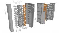
The P-leg materials are 15% a mix of Tellurium, Antimony, and Silver, and 85% a mix of Germanium and Tellurium, given the designation TAGS-85, plus a Tin-Tellurium segment on the hot side (on the right in the above image). The N-leg materials are a Lead-Tellurium mix designated 3M-TEGS- 2N(M). The 90 couples are grouped into six thermoelectric conversion modules of 15 couples each. The following image shows two of the modules in exploded views:
The couples are connected by copper straps. Pairs of couples are connected in parallel, and the pairs are connected in series. The couples in adjacent modules are interconnected by #9 gauge wires, forming a partial hex pattern above and below the RTG core that is visible in the overall exploded views. The full hex wire below the core is a magnetic compensation loop. The hot shoe (inboard end) of each couple is up against the graphite heat shield surrounding the fuel capsule (actually separated from the heat shield via a thin mica sheet for electrical insulation). The temperature of the heat shield surface - forming the hot side of the couple - is about 950F (about 510C). To maximize the temperature differential across the thermoelectric couples, a set of cold end hardware provides a thermally conductive path from the copper interconnect straps (which are soldered to the outboard ends of the P- and N-legs of the couples) to the relatively cool exterior RTG housing. The temperature of the exterior housing at the root of each of the six large cooling fins - which are directly adjacent to the six aluminum heat sink bars - is typically about 330F (about 160C). Starting from the moment of assembly, the RTG power output gradually decreased due to a number of factors:
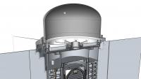
The effect of the Helium buildup was partly counteracted by a novel solution. The prominent dome on top of the generator, seen in section view in the following image, is a sealed reservoir filled with a 95% Argon / 5% Helium mix at assembly.
The generators cylindrical body was filled with a 90% Helium / 10% Argon mix. The initial high Helium fraction within the generator body was deliberately chosen to reduce the beginning-of-life power output. The months-long series of final RTG tests and storage prior to launch in Earths warm dense sea-level atmosphere would otherwise have produced RTG temperatures higher than desired. During cruise to Mars (in vacuum) and on the Mars surface (in a very cold low-pressure atmosphere) a higher energy conversion rate - and thus higher temperature differential - was wanted. The interface between the RTG body and reservoir dome was sealed as described earlier, but with an intentionally leaky seal. A dummy electrical receptacle with a Viton O-ring seal was installed between the body and dome. The dummy receptacle is the threaded object at top center of the ribbed RTG upper cover in the above section image. The O-ring permitted an extremely slow but effective gas exchange between RTG body and reservoir, raising the fraction of Argon (which is less thermally conductive than Helium) in the RTG and improving power generation. A great deal of effort was applied to mitigate risks of Plutonium fuel release that might occur due to launch accidents (explosions) or unintended spacecraft reentry into Earths atmosphere (if the booster rocket did not impart sufficient Earth-escape launch velocity). The following cut-away image shows the RTGs heat source (as the encapsulated plutonium fuel assembly was termed) in close-up:
To mitigate the effect of physical shocks and impacts, the fuel stack (olive-drab pucks) was encapsulated in a four-layer metal capsule consisting of the following, from inner to outer:
To mitigate the extreme heating that could occur if the RTG were to reenter the Earths atmosphere at nearly orbital speeds, the above capsule was first enclosed in three pyrolytic graphite sleeves, and then within a large hexagonal heat shield made of AXF-Ql fine grained isotropic Poco graphite, enclosed on both ends with graphite caps attached via stub Acme threads. The graphite is tolerant of extreme heating. In fact two earlier-version SNAP-19B RTGs were inadvertently subjected to moderate re-entry conditions when the NIMBUS B-1 spacecraft to which they were attached suffered a launch abort about one minute after liftoff in May 1968. The RTG housings were completely destroyed, but the heat sources were found and recovered from the Pacific ocean floor in October 1968 and examined in detail. The graphite heat shields were essentially intact. The SNAP-19 Viking RTG is marvelously simple in principle but subtly designed for extreme reliability. |
|||||||||
|
|
|
|||||||||
 Tom Dahl Viking '75 Mars Lander Construction May 17 2012, 12:38 AM
 tasp Can't remember where I read this, but at least... May 17 2012, 12:32 PM Tom Dahl I have begun creating a 3D model of the Viking lan... Jun 21 2012, 02:40 AM Tom Dahl I am looking for a good-quality version of an imag... Jul 9 2012, 02:06 AM djellison There is a model - I'm not sure of its fidelit... Aug 29 2012, 03:41 AM nprev IIRC, they've got the actual ground engineerin... Aug 29 2012, 09:38 AM Tom Dahl Hi Doug -- regarding the California Science Center... Aug 29 2012, 12:46 PM Tom Dahl In September had the opportunity to spend a couple... Nov 12 2012, 06:11 PM Tom Dahl A few months ago I was delighted to acquire a vint... Jun 7 2013, 03:57 PM Tom Dahl Thanks to the extremely kind assistance and cooper... Aug 17 2013, 06:44 PM Tom Dahl Here is a progress report on my 3D digital model o... Jun 23 2014, 02:43 AM elakdawalla Nice work, and thanks for sharing the SketchUp fil... Jun 23 2014, 03:17 PM Tom Dahl Update on my project to create a 3D digital model ... Nov 23 2014, 04:17 AM
 PaulH51 QUOTE (Tom Dahl @ Nov 23 2014, 12:17 PM) ... Nov 23 2014, 05:47 AM vikingmars QUOTE (Tom Dahl @ Nov 23 2014, 05:17 AM) ... Nov 23 2014, 09:22 AM
 Tom Dahl Today's update on my digital 3D SketchUp model... Aug 31 2015, 02:12 AM vikingmars QUOTE (Tom Dahl @ Aug 31 2015, 04:12 AM) ... Aug 31 2015, 07:57 AM droidtoaster Amazing Tom, thanks!
When I was at the CSC I ... Nov 24 2014, 12:35 AM Tom Dahl Here is some additional information on Viking land... Dec 21 2014, 09:17 PM pospa QUOTE (Tom Dahl @ Dec 21 2014, 11:17 PM) ... Jun 17 2015, 12:30 PM Mr Valiant Tom,
Your in depth examination of the Viking Land... Jun 18 2015, 12:17 AM Tom Dahl My on-going quest to research the Viking '75 m... Jun 17 2015, 12:47 AM monty python Wow Tom. Thanks much for the video. It gives me in... Aug 31 2015, 03:46 AM bear10829 In case you don't know about this particular t... Sep 4 2015, 09:27 AM Tom Dahl Hi bear10829, that is indeed a wonderful archive. ... Sep 4 2015, 02:17 PM RachelVL3 Tom,
Your progress is astounding and it is a plea... Nov 1 2015, 04:09 PM Tom Dahl Thank you Rachel, I appreciate the compliment and ... Nov 1 2015, 04:30 PM Tom Dahl I just completed a new video animation of my work-... Jan 16 2016, 02:15 PM Tom Tamlyn QUOTE (Tom Dahl @ Jan 16 2016, 10:15 AM) ... Jun 7 2016, 05:53 AM Tom Dahl My main goal is to model essentially all exterior ... Jun 7 2016, 11:42 PM Tom Dahl On May 20 I visited the Smithsonian National Air a... Jun 6 2016, 11:48 PM Tom Dahl I recently completed a 12-minute making-of video t... Aug 7 2016, 01:18 PM Tom Dahl This past weekend I completed a 3D digital model (... Nov 22 2016, 01:11 AM Tom Dahl I've completed modeling the hardware that moun... Dec 24 2016, 04:30 PM rlorenz QUOTE (Tom Dahl @ Dec 24 2016, 11:30 AM) ... Dec 25 2016, 03:58 PM Tom Dahl Making progress on the Surface Sampler Acquisition... Mar 28 2017, 02:53 PM djellison As someone who has dabbled in various 3D platforms... Mar 28 2017, 03:44 PM Tom Dahl Thank you for the compliment, Doug! It's a... Mar 29 2017, 11:24 PM djellison Yeah - structure from motion can struggle with fla... Mar 30 2017, 05:51 PM Tom Dahl Thanks for pointing out dead links. I have edited ... Mar 30 2017, 11:31 PM Tom Dahl During the past few weeks I've added the front... May 20 2017, 03:54 PM Tom Dahl Here are close-ups of the pedestal base and yoke g... May 20 2017, 03:59 PM Tom Dahl Next up are the components of the boom extend-retr... Jun 27 2017, 12:01 AM PaulH51 QUOTE (Tom Dahl @ Jun 27 2017, 08:01 AM) ... Jun 27 2017, 09:45 AM monty python Thanks. Always wondered how that worked. Jun 28 2017, 05:31 AM Tom Dahl The Viking lander's Surface Sampler Acquisitio... Aug 4 2017, 04:14 PM Tom Dahl I've completed a detailed (nearly 18 minutes l... Jan 14 2018, 12:37 AM vikingmars QUOTE (Tom Dahl @ Jan 14 2018, 01:37 AM) ... Jan 14 2018, 08:37 AM monty python Tom, that is fantastic! I am old enough to rem... Jan 14 2018, 09:14 AM Floyd Tom, thank you for a fantastic movie. It is visua... Jan 14 2018, 03:24 PM john_s Beautiful engineering, beautifully rendered and pr... Jan 26 2018, 09:23 PM PFK As a humble chemist (albeit one who vividly rememb... Jan 27 2018, 11:44 AM Tom Dahl The next chapter in the effort to create a high-fi... Jan 9 2019, 12:51 AM PaulH51 QUOTE (Tom Dahl @ Jan 9 2019, 08:51 AM) T... Jan 9 2019, 01:31 AM sittingduck Tom, what you're doing is not only historical ... Jan 9 2019, 03:41 PM Tom Dahl I've completed the remaining two communication... Oct 3 2019, 02:12 AM scalbers Nice to see these antennas again. I especially rec... Oct 3 2019, 09:56 PM mcaplinger Over on nasawatch it's being claimed that the ... Apr 2 2020, 07:46 PM climber QUOTE (mcaplinger @ Apr 2 2020, 08:46 PM)... Apr 2 2020, 08:49 PM atomoid its already April 2nd, so what the heck is the NAS... Apr 2 2020, 10:13 PM Tom Dahl As far as I know, the NASA "worm" logo d... Apr 2 2020, 10:57 PM Tom Dahl I have completed a 22-minute video that describes ... Jul 8 2020, 12:02 PM Tom Dahl The latest addition to my work-in-progress Viking ... Apr 18 2021, 02:42 AM Tom Dahl Here are detailed views of the MR-50F roll-control... Apr 18 2021, 02:53 AM Tom Dahl Here are details of the pair of main valves on eac... Apr 18 2021, 03:08 AM Tom Dahl I have been adding some major internal components ... Oct 23 2021, 12:38 AM vikingmars QUOTE (Tom Dahl @ Oct 23 2021, 02:38 AM) ... Oct 25 2021, 10:02 PM Tom Dahl The next Viking lander component 3D models to be c... May 19 2022, 10:39 PM scalbers Here are a few recent photos of the spare flight q... Jan 2 2023, 07:43 PM Tom Dahl Indeed the Flight Capsule 3 or FC3/VL3 backup land... Jan 3 2023, 12:31 AM BYEMAN Just wondering if anybody has come across a docume... Jan 3 2023, 12:48 AM Tom Dahl QUOTE (BYEMAN @ Jan 2 2023, 07:48 PM) Jus... Jan 4 2023, 02:46 AM Floyd Thank you Tom. The models and writeup are outstan... Jun 7 2023, 02:43 PM mcaplinger Great post on the RTGs, Tom! Looking forward ... Jun 7 2023, 03:37 PM Tom Dahl Indeed it surely was pretty hot within the lander... Jun 7 2023, 11:08 PM rlorenz QUOTE (Tom Dahl @ Jun 7 2023, 06:08 PM) .... Jul 22 2023, 01:02 AM Tom Dahl I have completed integrating the SNAP-19 Viking RT... Jul 15 2023, 06:57 PM Tom Dahl Here are exploded views of the wind cover for RTG ... Jul 15 2023, 07:48 PM Tom Dahl Here are renderings of the entire RTG installation... Jul 15 2023, 07:51 PM Tom Dahl Lastly (for now!) here is an overall view of t... Jul 15 2023, 07:56 PM Tom Dahl I just completed a 21-minute video describing the ... Dec 27 2023, 11:35 PM vikingmars QUOTE (Tom Dahl @ Dec 28 2023, 12:35 AM) ... Dec 28 2023, 12:58 PM john_s Second that- wonderful and amazing stuff, and I le... Dec 28 2023, 03:12 PM Glevesque QUOTE (Tom Dahl @ Dec 27 2023, 06:35 PM) ... Dec 30 2023, 05:28 PM
Tom Dahl Today's update on my digital 3D SketchUp model... Aug 31 2015, 02:12 AM vikingmars QUOTE (Tom Dahl @ Aug 31 2015, 04:12 AM) ... Aug 31 2015, 07:57 AM droidtoaster Amazing Tom, thanks!
When I was at the CSC I ... Nov 24 2014, 12:35 AM Tom Dahl Here is some additional information on Viking land... Dec 21 2014, 09:17 PM pospa QUOTE (Tom Dahl @ Dec 21 2014, 11:17 PM) ... Jun 17 2015, 12:30 PM Mr Valiant Tom,
Your in depth examination of the Viking Land... Jun 18 2015, 12:17 AM Tom Dahl My on-going quest to research the Viking '75 m... Jun 17 2015, 12:47 AM monty python Wow Tom. Thanks much for the video. It gives me in... Aug 31 2015, 03:46 AM bear10829 In case you don't know about this particular t... Sep 4 2015, 09:27 AM Tom Dahl Hi bear10829, that is indeed a wonderful archive. ... Sep 4 2015, 02:17 PM RachelVL3 Tom,
Your progress is astounding and it is a plea... Nov 1 2015, 04:09 PM Tom Dahl Thank you Rachel, I appreciate the compliment and ... Nov 1 2015, 04:30 PM Tom Dahl I just completed a new video animation of my work-... Jan 16 2016, 02:15 PM Tom Tamlyn QUOTE (Tom Dahl @ Jan 16 2016, 10:15 AM) ... Jun 7 2016, 05:53 AM Tom Dahl My main goal is to model essentially all exterior ... Jun 7 2016, 11:42 PM Tom Dahl On May 20 I visited the Smithsonian National Air a... Jun 6 2016, 11:48 PM Tom Dahl I recently completed a 12-minute making-of video t... Aug 7 2016, 01:18 PM Tom Dahl This past weekend I completed a 3D digital model (... Nov 22 2016, 01:11 AM Tom Dahl I've completed modeling the hardware that moun... Dec 24 2016, 04:30 PM rlorenz QUOTE (Tom Dahl @ Dec 24 2016, 11:30 AM) ... Dec 25 2016, 03:58 PM Tom Dahl Making progress on the Surface Sampler Acquisition... Mar 28 2017, 02:53 PM djellison As someone who has dabbled in various 3D platforms... Mar 28 2017, 03:44 PM Tom Dahl Thank you for the compliment, Doug! It's a... Mar 29 2017, 11:24 PM djellison Yeah - structure from motion can struggle with fla... Mar 30 2017, 05:51 PM Tom Dahl Thanks for pointing out dead links. I have edited ... Mar 30 2017, 11:31 PM Tom Dahl During the past few weeks I've added the front... May 20 2017, 03:54 PM Tom Dahl Here are close-ups of the pedestal base and yoke g... May 20 2017, 03:59 PM Tom Dahl Next up are the components of the boom extend-retr... Jun 27 2017, 12:01 AM PaulH51 QUOTE (Tom Dahl @ Jun 27 2017, 08:01 AM) ... Jun 27 2017, 09:45 AM monty python Thanks. Always wondered how that worked. Jun 28 2017, 05:31 AM Tom Dahl The Viking lander's Surface Sampler Acquisitio... Aug 4 2017, 04:14 PM Tom Dahl I've completed a detailed (nearly 18 minutes l... Jan 14 2018, 12:37 AM vikingmars QUOTE (Tom Dahl @ Jan 14 2018, 01:37 AM) ... Jan 14 2018, 08:37 AM monty python Tom, that is fantastic! I am old enough to rem... Jan 14 2018, 09:14 AM Floyd Tom, thank you for a fantastic movie. It is visua... Jan 14 2018, 03:24 PM john_s Beautiful engineering, beautifully rendered and pr... Jan 26 2018, 09:23 PM PFK As a humble chemist (albeit one who vividly rememb... Jan 27 2018, 11:44 AM Tom Dahl The next chapter in the effort to create a high-fi... Jan 9 2019, 12:51 AM PaulH51 QUOTE (Tom Dahl @ Jan 9 2019, 08:51 AM) T... Jan 9 2019, 01:31 AM sittingduck Tom, what you're doing is not only historical ... Jan 9 2019, 03:41 PM Tom Dahl I've completed the remaining two communication... Oct 3 2019, 02:12 AM scalbers Nice to see these antennas again. I especially rec... Oct 3 2019, 09:56 PM mcaplinger Over on nasawatch it's being claimed that the ... Apr 2 2020, 07:46 PM climber QUOTE (mcaplinger @ Apr 2 2020, 08:46 PM)... Apr 2 2020, 08:49 PM atomoid its already April 2nd, so what the heck is the NAS... Apr 2 2020, 10:13 PM Tom Dahl As far as I know, the NASA "worm" logo d... Apr 2 2020, 10:57 PM Tom Dahl I have completed a 22-minute video that describes ... Jul 8 2020, 12:02 PM Tom Dahl The latest addition to my work-in-progress Viking ... Apr 18 2021, 02:42 AM Tom Dahl Here are detailed views of the MR-50F roll-control... Apr 18 2021, 02:53 AM Tom Dahl Here are details of the pair of main valves on eac... Apr 18 2021, 03:08 AM Tom Dahl I have been adding some major internal components ... Oct 23 2021, 12:38 AM vikingmars QUOTE (Tom Dahl @ Oct 23 2021, 02:38 AM) ... Oct 25 2021, 10:02 PM Tom Dahl The next Viking lander component 3D models to be c... May 19 2022, 10:39 PM scalbers Here are a few recent photos of the spare flight q... Jan 2 2023, 07:43 PM Tom Dahl Indeed the Flight Capsule 3 or FC3/VL3 backup land... Jan 3 2023, 12:31 AM BYEMAN Just wondering if anybody has come across a docume... Jan 3 2023, 12:48 AM Tom Dahl QUOTE (BYEMAN @ Jan 2 2023, 07:48 PM) Jus... Jan 4 2023, 02:46 AM Floyd Thank you Tom. The models and writeup are outstan... Jun 7 2023, 02:43 PM mcaplinger Great post on the RTGs, Tom! Looking forward ... Jun 7 2023, 03:37 PM Tom Dahl Indeed it surely was pretty hot within the lander... Jun 7 2023, 11:08 PM rlorenz QUOTE (Tom Dahl @ Jun 7 2023, 06:08 PM) .... Jul 22 2023, 01:02 AM Tom Dahl I have completed integrating the SNAP-19 Viking RT... Jul 15 2023, 06:57 PM Tom Dahl Here are exploded views of the wind cover for RTG ... Jul 15 2023, 07:48 PM Tom Dahl Here are renderings of the entire RTG installation... Jul 15 2023, 07:51 PM Tom Dahl Lastly (for now!) here is an overall view of t... Jul 15 2023, 07:56 PM Tom Dahl I just completed a 21-minute video describing the ... Dec 27 2023, 11:35 PM vikingmars QUOTE (Tom Dahl @ Dec 28 2023, 12:35 AM) ... Dec 28 2023, 12:58 PM john_s Second that- wonderful and amazing stuff, and I le... Dec 28 2023, 03:12 PM Glevesque QUOTE (Tom Dahl @ Dec 27 2023, 06:35 PM) ... Dec 30 2023, 05:28 PM |

|
Lo-Fi Version | Time is now: 23rd September 2024 - 11:44 AM |
|
RULES AND GUIDELINES Please read the Forum Rules and Guidelines before posting. IMAGE COPYRIGHT |
OPINIONS AND MODERATION Opinions expressed on UnmannedSpaceflight.com are those of the individual posters and do not necessarily reflect the opinions of UnmannedSpaceflight.com or The Planetary Society. The all-volunteer UnmannedSpaceflight.com moderation team is wholly independent of The Planetary Society. The Planetary Society has no influence over decisions made by the UnmannedSpaceflight.com moderators. |
SUPPORT THE FORUM Unmannedspaceflight.com is funded by the Planetary Society. Please consider supporting our work and many other projects by donating to the Society or becoming a member. |
|