Viking '75 Mars Lander Construction, Looking for Viking lander design/construction information |

Viking '75 Mars Lander Construction, Looking for Viking lander design/construction information |
 May 17 2012, 12:38 AM May 17 2012, 12:38 AM
Post
#1
|
|
 Member  Group: Members Posts: 101 Joined: 3-May 12 From: Massachusetts, USA Member No.: 6392 |
Greetings all! I am searching for detailed construction and design information about the NASA Viking '75 Mars project hardware, particularly for the lander, aeroshell, base cover, and bioshield. Can anyone recommend good sources? I am especially looking for engineering drawings and under-construction photographs.
To set the stage, here is an album of about 100 drawings and photos which I've collected so far. I have already read the "usual" books, such as NASA RP-1027 "Viking '75 Spacecraft Design and Test", the press kits, the scientific papers produced about the mission, a number of industry papers covering various instruments and subsystems, the major Martin Marietta books, etc. I am hoping to find additional sources. Any ideas? Also, does anyone know if there are aeroshell, base cover, or bioshield components lurking in a museum or in storage somewhere? FYI, I have visited three of the best landers still on Earth: The Proof Test Capsule in the Smithsonian NASM, the Flight Capsule 3 (backup) in the Museum of Flight near Seattle, and the Science Test Lander in the Virginia Air and Space Center. I've taken nearly 1,000 photos of the three of them (most of which are publicly available in other Picasa Web albums of mine). I've taken a few measurements, but I would dearly love to find more authoritative drawings of more hardware (interior, exterior, everything). I have begun submitting some Freedom of Information Act requests to NASA/JPL which has started to bear some trivial but kind of fun fruit. --- Update as of March 2017: During the past few years I have been fortunate enough to collect a significant amount of information on the Viking lander hardware. My thanks to a number of organizations for providing me access to their resources:
Flight Capsule 3 in Seattle Museum of Flight (756 photos) Dimensioned diagrams of the FC3 lander PTC Lander at Smithsonian NASM 2013 (466 photos) PTC Lander at Smithsonian NASM 2016 (888 photos) Lander at Virginia Air and Space Center (622 photos) Dimensioned diagrams of the VASCs lander Lander at California Science Center (456 photos) Dimensioned diagrams of the CSC's lander Misc diagrams, unusual photos (over 350 images) Body assembly blueprints Collector Head Shroud Unit at NASA LaRC (99 photos) Biology instrument at Cleveland MoNH (36 photos) Meteorology Sensor Assembly (60 photos) Meteorology Electronics Assembly (22 photos) Tape Recorder (53 photos) High Gain Antenna photos and measurements (96 images) XRFS Instrument (42 images) Viking lander contractor historic scale model (14 images) My Viking project documents collection The main focus of my efforts during the past few years has been to create an accurate and high-fidelity digital 3D model of the Viking lander. I've chosen to use the SketchUp software to build the model because a near-full-featured free version is available, allowing other people to use my model. The 3D model itself, as a work-in-progress, is available via DropBox. I update that model file periodically as major elements get added. I've created an album containing numerous renderings of digital model components, and I have a YouTube channel with some videos about the modeling project. I have also uploaded the lander core body and the Surface Sampler Collector Head to the SketchUp 3D Warehouse so that other people can easily access those components (the 3D Warehouse can be accessed from within SketchUp, or via web browser). The file on DropBox lister earlier contains those components and others. -- Tom |
 |
 
|
 |
|
Jul 15 2023, 07:48 PM
Post
#2
|
|||||
|
Member Group: Members Posts: 101 Joined: 3-May 12 From: Massachusetts, USA Member No.: 6392 |
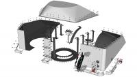
Here are exploded views of the wind cover for RTG #2. The two wind covers are nearly-identical mirror images of each other. They differ primarily in small items attached to the front face of the wind cover, and that the top of wind cover #2 has an indentation for clearance of the Low Gain Antenna which is located very close to the wind cover. As can be seen, the wind covers are more complicated than they perhaps appear. Each wind cover has internal stiffening ribs along the side and an internal panel near front-center. Each wind cover has a large circular vent on its bottom face near a front corner (visible left of center in the second exploded view below). The vent allows equalization of pressure during launch from Earth and landing on Mars, and is covered with fine mesh to filter out most Martian atmospheric dust. Each wind cover has a camera Reference Test Chart (RTC) attached to its front face. The RTC itself is exploded in these views. A small skirt surrounds the sides and front of the wind cover bottom edge, to minimize build-up of Mars dust under the wind cover during the mission.
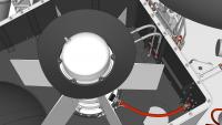
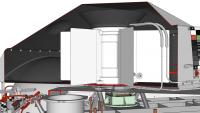
Here are close-up views of RTG 2 within its wind cover, starting with a top view. The large conical Upper End Cap Cooler (ECC) is prominent surrounding the reservoir dome atop the RTG housing. The rear rim of the ECC is clipped for clearance within the sloping top of the wind cover. The curving coolant loop inlet and outlet lines are prominent in the upper right of the image. The flat disc radiator fin of the lower ECC blends into the black interior of the wind cover bottom, but it is quite large and obvious when you know what to look for. The rear edge of the radiator fin is also clipped to clear the wind cover's large spherical inward-bulging rear which in turn provides clearance for the lander's nearby propellant tank. The large red cable in the lower right carries the 4.4 volt DC electric output of the RTG, along with six instrumentation signal lines (two each for an internal pressure transducer, a fin root thermistor which measured the temperature of the interior surface of the RTG housing, and a Resistive Temperature Detector (RTD) which measured the temperature of one of the thermocouple pairs surrounding the RTG's internal heat source). The small cream-colored cable passing through an electrical connector near bottom-center delivers the signal from a hazard monitor thermistor which measured the exterior temperature of the RTG housing.
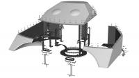
Here is a side view of RTG and wind cover 2 that is cut away to reveal RTG mounting details. The lower ECC has a flattish gray (I believe cast aluminum) body with a somewhat irregular shape. The coolant loop lines enter and exit from the right portion of the ECC body. Four stout tabs (only one of which is easily visible here below-center of the image) mount the ECC, and thus the RTG and wind cover, to the lander structure. The ECC's two inboard tabs are supported on titanium (for low thermal conductance) U-channel tripods and bipods (with lightening holes) that are in turn mounted to the Equipment Plate within the upper interior of the lander. The green-tinted object between the tripod and bipod and below the RTG front edge is a Thermal Switch for transferring variable amounts of RTG heat into the lander. The ECC's two outboard tabs bolt to small extensions of the lander body side beam structure. The lower ECC's flat disc radiator fin is cut away to better reveal the ECC body below the fin. The disc fin is thin on its outer perimeter, thickening toward its slightly depressed center. The dark conical upper ECC is easily visible atop the RTG housing, and the coolant loop inlet and outlet lines can be seen passing into the upper ECC base. The larger-diameter striped segments of the coolant loop represent braided flexible hoses used in that area. The remainder of the coolant loop is rigid 0.25 inch tubing.
|
||||
|
|
|
||||
 Tom Dahl Viking '75 Mars Lander Construction May 17 2012, 12:38 AM
 tasp Can't remember where I read this, but at least... May 17 2012, 12:32 PM Tom Dahl I have begun creating a 3D model of the Viking lan... Jun 21 2012, 02:40 AM Tom Dahl I am looking for a good-quality version of an imag... Jul 9 2012, 02:06 AM djellison There is a model - I'm not sure of its fidelit... Aug 29 2012, 03:41 AM nprev IIRC, they've got the actual ground engineerin... Aug 29 2012, 09:38 AM Tom Dahl Hi Doug -- regarding the California Science Center... Aug 29 2012, 12:46 PM Tom Dahl In September had the opportunity to spend a couple... Nov 12 2012, 06:11 PM Tom Dahl A few months ago I was delighted to acquire a vint... Jun 7 2013, 03:57 PM Tom Dahl Thanks to the extremely kind assistance and cooper... Aug 17 2013, 06:44 PM Tom Dahl Here is a progress report on my 3D digital model o... Jun 23 2014, 02:43 AM elakdawalla Nice work, and thanks for sharing the SketchUp fil... Jun 23 2014, 03:17 PM Tom Dahl Update on my project to create a 3D digital model ... Nov 23 2014, 04:17 AM
 PaulH51 QUOTE (Tom Dahl @ Nov 23 2014, 12:17 PM) ... Nov 23 2014, 05:47 AM vikingmars QUOTE (Tom Dahl @ Nov 23 2014, 05:17 AM) ... Nov 23 2014, 09:22 AM
 Tom Dahl Today's update on my digital 3D SketchUp model... Aug 31 2015, 02:12 AM vikingmars QUOTE (Tom Dahl @ Aug 31 2015, 04:12 AM) ... Aug 31 2015, 07:57 AM droidtoaster Amazing Tom, thanks!
When I was at the CSC I ... Nov 24 2014, 12:35 AM Tom Dahl Here is some additional information on Viking land... Dec 21 2014, 09:17 PM pospa QUOTE (Tom Dahl @ Dec 21 2014, 11:17 PM) ... Jun 17 2015, 12:30 PM Mr Valiant Tom,
Your in depth examination of the Viking Land... Jun 18 2015, 12:17 AM Tom Dahl My on-going quest to research the Viking '75 m... Jun 17 2015, 12:47 AM monty python Wow Tom. Thanks much for the video. It gives me in... Aug 31 2015, 03:46 AM bear10829 In case you don't know about this particular t... Sep 4 2015, 09:27 AM Tom Dahl Hi bear10829, that is indeed a wonderful archive. ... Sep 4 2015, 02:17 PM RachelVL3 Tom,
Your progress is astounding and it is a plea... Nov 1 2015, 04:09 PM Tom Dahl Thank you Rachel, I appreciate the compliment and ... Nov 1 2015, 04:30 PM Tom Dahl I just completed a new video animation of my work-... Jan 16 2016, 02:15 PM Tom Tamlyn QUOTE (Tom Dahl @ Jan 16 2016, 10:15 AM) ... Jun 7 2016, 05:53 AM Tom Dahl My main goal is to model essentially all exterior ... Jun 7 2016, 11:42 PM Tom Dahl On May 20 I visited the Smithsonian National Air a... Jun 6 2016, 11:48 PM Tom Dahl I recently completed a 12-minute making-of video t... Aug 7 2016, 01:18 PM Tom Dahl This past weekend I completed a 3D digital model (... Nov 22 2016, 01:11 AM Tom Dahl I've completed modeling the hardware that moun... Dec 24 2016, 04:30 PM rlorenz QUOTE (Tom Dahl @ Dec 24 2016, 11:30 AM) ... Dec 25 2016, 03:58 PM Tom Dahl Making progress on the Surface Sampler Acquisition... Mar 28 2017, 02:53 PM djellison As someone who has dabbled in various 3D platforms... Mar 28 2017, 03:44 PM Tom Dahl Thank you for the compliment, Doug! It's a... Mar 29 2017, 11:24 PM djellison Yeah - structure from motion can struggle with fla... Mar 30 2017, 05:51 PM Tom Dahl Thanks for pointing out dead links. I have edited ... Mar 30 2017, 11:31 PM Tom Dahl During the past few weeks I've added the front... May 20 2017, 03:54 PM Tom Dahl Here are close-ups of the pedestal base and yoke g... May 20 2017, 03:59 PM Tom Dahl Next up are the components of the boom extend-retr... Jun 27 2017, 12:01 AM PaulH51 QUOTE (Tom Dahl @ Jun 27 2017, 08:01 AM) ... Jun 27 2017, 09:45 AM monty python Thanks. Always wondered how that worked. Jun 28 2017, 05:31 AM Tom Dahl The Viking lander's Surface Sampler Acquisitio... Aug 4 2017, 04:14 PM Tom Dahl I've completed a detailed (nearly 18 minutes l... Jan 14 2018, 12:37 AM vikingmars QUOTE (Tom Dahl @ Jan 14 2018, 01:37 AM) ... Jan 14 2018, 08:37 AM monty python Tom, that is fantastic! I am old enough to rem... Jan 14 2018, 09:14 AM Floyd Tom, thank you for a fantastic movie. It is visua... Jan 14 2018, 03:24 PM john_s Beautiful engineering, beautifully rendered and pr... Jan 26 2018, 09:23 PM PFK As a humble chemist (albeit one who vividly rememb... Jan 27 2018, 11:44 AM Tom Dahl The next chapter in the effort to create a high-fi... Jan 9 2019, 12:51 AM PaulH51 QUOTE (Tom Dahl @ Jan 9 2019, 08:51 AM) T... Jan 9 2019, 01:31 AM sittingduck Tom, what you're doing is not only historical ... Jan 9 2019, 03:41 PM Tom Dahl I've completed the remaining two communication... Oct 3 2019, 02:12 AM scalbers Nice to see these antennas again. I especially rec... Oct 3 2019, 09:56 PM mcaplinger Over on nasawatch it's being claimed that the ... Apr 2 2020, 07:46 PM climber QUOTE (mcaplinger @ Apr 2 2020, 08:46 PM)... Apr 2 2020, 08:49 PM atomoid its already April 2nd, so what the heck is the NAS... Apr 2 2020, 10:13 PM Tom Dahl As far as I know, the NASA "worm" logo d... Apr 2 2020, 10:57 PM Tom Dahl I have completed a 22-minute video that describes ... Jul 8 2020, 12:02 PM Tom Dahl The latest addition to my work-in-progress Viking ... Apr 18 2021, 02:42 AM Tom Dahl Here are detailed views of the MR-50F roll-control... Apr 18 2021, 02:53 AM Tom Dahl Here are details of the pair of main valves on eac... Apr 18 2021, 03:08 AM Tom Dahl I have been adding some major internal components ... Oct 23 2021, 12:38 AM vikingmars QUOTE (Tom Dahl @ Oct 23 2021, 02:38 AM) ... Oct 25 2021, 10:02 PM Tom Dahl The next Viking lander component 3D models to be c... May 19 2022, 10:39 PM scalbers Here are a few recent photos of the spare flight q... Jan 2 2023, 07:43 PM Tom Dahl Indeed the Flight Capsule 3 or FC3/VL3 backup land... Jan 3 2023, 12:31 AM BYEMAN Just wondering if anybody has come across a docume... Jan 3 2023, 12:48 AM Tom Dahl QUOTE (BYEMAN @ Jan 2 2023, 07:48 PM) Jus... Jan 4 2023, 02:46 AM Tom Dahl I have recently completed modeling the Viking land... Jun 7 2023, 12:55 PM Floyd Thank you Tom. The models and writeup are outstan... Jun 7 2023, 02:43 PM mcaplinger Great post on the RTGs, Tom! Looking forward ... Jun 7 2023, 03:37 PM Tom Dahl Indeed it surely was pretty hot within the lander... Jun 7 2023, 11:08 PM rlorenz QUOTE (Tom Dahl @ Jun 7 2023, 06:08 PM) .... Jul 22 2023, 01:02 AM Tom Dahl I have completed integrating the SNAP-19 Viking RT... Jul 15 2023, 06:57 PM Tom Dahl Here are renderings of the entire RTG installation... Jul 15 2023, 07:51 PM Tom Dahl Lastly (for now!) here is an overall view of t... Jul 15 2023, 07:56 PM Tom Dahl I just completed a 21-minute video describing the ... Dec 27 2023, 11:35 PM vikingmars QUOTE (Tom Dahl @ Dec 28 2023, 12:35 AM) ... Dec 28 2023, 12:58 PM john_s Second that- wonderful and amazing stuff, and I le... Dec 28 2023, 03:12 PM Glevesque QUOTE (Tom Dahl @ Dec 27 2023, 06:35 PM) ... Dec 30 2023, 05:28 PM
Tom Dahl Today's update on my digital 3D SketchUp model... Aug 31 2015, 02:12 AM vikingmars QUOTE (Tom Dahl @ Aug 31 2015, 04:12 AM) ... Aug 31 2015, 07:57 AM droidtoaster Amazing Tom, thanks!
When I was at the CSC I ... Nov 24 2014, 12:35 AM Tom Dahl Here is some additional information on Viking land... Dec 21 2014, 09:17 PM pospa QUOTE (Tom Dahl @ Dec 21 2014, 11:17 PM) ... Jun 17 2015, 12:30 PM Mr Valiant Tom,
Your in depth examination of the Viking Land... Jun 18 2015, 12:17 AM Tom Dahl My on-going quest to research the Viking '75 m... Jun 17 2015, 12:47 AM monty python Wow Tom. Thanks much for the video. It gives me in... Aug 31 2015, 03:46 AM bear10829 In case you don't know about this particular t... Sep 4 2015, 09:27 AM Tom Dahl Hi bear10829, that is indeed a wonderful archive. ... Sep 4 2015, 02:17 PM RachelVL3 Tom,
Your progress is astounding and it is a plea... Nov 1 2015, 04:09 PM Tom Dahl Thank you Rachel, I appreciate the compliment and ... Nov 1 2015, 04:30 PM Tom Dahl I just completed a new video animation of my work-... Jan 16 2016, 02:15 PM Tom Tamlyn QUOTE (Tom Dahl @ Jan 16 2016, 10:15 AM) ... Jun 7 2016, 05:53 AM Tom Dahl My main goal is to model essentially all exterior ... Jun 7 2016, 11:42 PM Tom Dahl On May 20 I visited the Smithsonian National Air a... Jun 6 2016, 11:48 PM Tom Dahl I recently completed a 12-minute making-of video t... Aug 7 2016, 01:18 PM Tom Dahl This past weekend I completed a 3D digital model (... Nov 22 2016, 01:11 AM Tom Dahl I've completed modeling the hardware that moun... Dec 24 2016, 04:30 PM rlorenz QUOTE (Tom Dahl @ Dec 24 2016, 11:30 AM) ... Dec 25 2016, 03:58 PM Tom Dahl Making progress on the Surface Sampler Acquisition... Mar 28 2017, 02:53 PM djellison As someone who has dabbled in various 3D platforms... Mar 28 2017, 03:44 PM Tom Dahl Thank you for the compliment, Doug! It's a... Mar 29 2017, 11:24 PM djellison Yeah - structure from motion can struggle with fla... Mar 30 2017, 05:51 PM Tom Dahl Thanks for pointing out dead links. I have edited ... Mar 30 2017, 11:31 PM Tom Dahl During the past few weeks I've added the front... May 20 2017, 03:54 PM Tom Dahl Here are close-ups of the pedestal base and yoke g... May 20 2017, 03:59 PM Tom Dahl Next up are the components of the boom extend-retr... Jun 27 2017, 12:01 AM PaulH51 QUOTE (Tom Dahl @ Jun 27 2017, 08:01 AM) ... Jun 27 2017, 09:45 AM monty python Thanks. Always wondered how that worked. Jun 28 2017, 05:31 AM Tom Dahl The Viking lander's Surface Sampler Acquisitio... Aug 4 2017, 04:14 PM Tom Dahl I've completed a detailed (nearly 18 minutes l... Jan 14 2018, 12:37 AM vikingmars QUOTE (Tom Dahl @ Jan 14 2018, 01:37 AM) ... Jan 14 2018, 08:37 AM monty python Tom, that is fantastic! I am old enough to rem... Jan 14 2018, 09:14 AM Floyd Tom, thank you for a fantastic movie. It is visua... Jan 14 2018, 03:24 PM john_s Beautiful engineering, beautifully rendered and pr... Jan 26 2018, 09:23 PM PFK As a humble chemist (albeit one who vividly rememb... Jan 27 2018, 11:44 AM Tom Dahl The next chapter in the effort to create a high-fi... Jan 9 2019, 12:51 AM PaulH51 QUOTE (Tom Dahl @ Jan 9 2019, 08:51 AM) T... Jan 9 2019, 01:31 AM sittingduck Tom, what you're doing is not only historical ... Jan 9 2019, 03:41 PM Tom Dahl I've completed the remaining two communication... Oct 3 2019, 02:12 AM scalbers Nice to see these antennas again. I especially rec... Oct 3 2019, 09:56 PM mcaplinger Over on nasawatch it's being claimed that the ... Apr 2 2020, 07:46 PM climber QUOTE (mcaplinger @ Apr 2 2020, 08:46 PM)... Apr 2 2020, 08:49 PM atomoid its already April 2nd, so what the heck is the NAS... Apr 2 2020, 10:13 PM Tom Dahl As far as I know, the NASA "worm" logo d... Apr 2 2020, 10:57 PM Tom Dahl I have completed a 22-minute video that describes ... Jul 8 2020, 12:02 PM Tom Dahl The latest addition to my work-in-progress Viking ... Apr 18 2021, 02:42 AM Tom Dahl Here are detailed views of the MR-50F roll-control... Apr 18 2021, 02:53 AM Tom Dahl Here are details of the pair of main valves on eac... Apr 18 2021, 03:08 AM Tom Dahl I have been adding some major internal components ... Oct 23 2021, 12:38 AM vikingmars QUOTE (Tom Dahl @ Oct 23 2021, 02:38 AM) ... Oct 25 2021, 10:02 PM Tom Dahl The next Viking lander component 3D models to be c... May 19 2022, 10:39 PM scalbers Here are a few recent photos of the spare flight q... Jan 2 2023, 07:43 PM Tom Dahl Indeed the Flight Capsule 3 or FC3/VL3 backup land... Jan 3 2023, 12:31 AM BYEMAN Just wondering if anybody has come across a docume... Jan 3 2023, 12:48 AM Tom Dahl QUOTE (BYEMAN @ Jan 2 2023, 07:48 PM) Jus... Jan 4 2023, 02:46 AM Tom Dahl I have recently completed modeling the Viking land... Jun 7 2023, 12:55 PM Floyd Thank you Tom. The models and writeup are outstan... Jun 7 2023, 02:43 PM mcaplinger Great post on the RTGs, Tom! Looking forward ... Jun 7 2023, 03:37 PM Tom Dahl Indeed it surely was pretty hot within the lander... Jun 7 2023, 11:08 PM rlorenz QUOTE (Tom Dahl @ Jun 7 2023, 06:08 PM) .... Jul 22 2023, 01:02 AM Tom Dahl I have completed integrating the SNAP-19 Viking RT... Jul 15 2023, 06:57 PM Tom Dahl Here are renderings of the entire RTG installation... Jul 15 2023, 07:51 PM Tom Dahl Lastly (for now!) here is an overall view of t... Jul 15 2023, 07:56 PM Tom Dahl I just completed a 21-minute video describing the ... Dec 27 2023, 11:35 PM vikingmars QUOTE (Tom Dahl @ Dec 28 2023, 12:35 AM) ... Dec 28 2023, 12:58 PM john_s Second that- wonderful and amazing stuff, and I le... Dec 28 2023, 03:12 PM Glevesque QUOTE (Tom Dahl @ Dec 27 2023, 06:35 PM) ... Dec 30 2023, 05:28 PM |

|
Lo-Fi Version | Time is now: 22nd September 2024 - 12:10 AM |
|
RULES AND GUIDELINES Please read the Forum Rules and Guidelines before posting. IMAGE COPYRIGHT |
OPINIONS AND MODERATION Opinions expressed on UnmannedSpaceflight.com are those of the individual posters and do not necessarily reflect the opinions of UnmannedSpaceflight.com or The Planetary Society. The all-volunteer UnmannedSpaceflight.com moderation team is wholly independent of The Planetary Society. The Planetary Society has no influence over decisions made by the UnmannedSpaceflight.com moderators. |
SUPPORT THE FORUM Unmannedspaceflight.com is funded by the Planetary Society. Please consider supporting our work and many other projects by donating to the Society or becoming a member. |
|