Processing VIMS cubes, An attempt at "true" color |

Processing VIMS cubes, An attempt at "true" color |
 Sep 10 2006, 07:51 PM Sep 10 2006, 07:51 PM
Post
#1
|
||||||||
 Senior Member  Group: Members Posts: 3648 Joined: 1-October 05 From: Croatia Member No.: 523 |
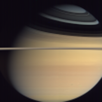
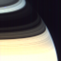
Right, a suggestion I made here in another topic made me wonder why not try that myself. A bunch of data was sitting on the PDS, after all. After a hassle figuring out just how the image cubes are organized and trying to read them, finally I was able to produce some results. This is all very rough work, can be considered first-iteration only and not particularly accurate.
Basically, I used the cubes to extract the visible spectrum in the 380-780 nanometer range which was then input to color matching code I found here by Andrew T. Young. The code integrates over 40 10-nm steps to produce CIE XYZ color components. I then converted these to RGB values. I'm aware of at least three inaccuracies in my code as of yet: one is the above sampled code apparently uses Illuminant C as the light source, not true solar spectra so the color turns out bluish (has a temp. of 9300 K instead of 6500 K, AFAIK). I tried to compensate at the moment by changing the final RGB white balance, but this is probably an inaccurate way to go. Another inaccuracy is I don't do bias removal from the cubes. This likely affects the outcome. Also, I don't use the precise wavelengths the code requires, but use the closest one in the cube. I intend to fix this by interpolating between nearest wavelengths. All images are enlarged 4x.
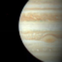
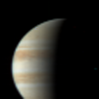
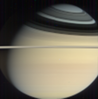
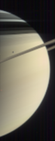
The leftmost image is a 4-cube mosaic. The colors in all four frames turned out identical which gives me at least some confidence. The image in the middle shows Dione's disc creeping in front of Saturn. Dione's disc appears elongated probably because as the lines were readout, it moved considerably in its orbit. The rightmost image shows a very overexposed Saturn image, the part below the ring shadows got overexposed. From what I've seen browsing through the PDS, a lot of the cubes are badly overexposed at some wavelengths. Here's a couple of Jupiter images. I'm not very satisfied with them as they seem to look somewhat greenish, but overall the color looks believeable:
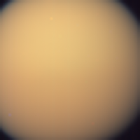
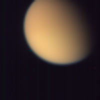
Lastly, two Titan composites. They turned out way more reddish than I thought they would.
It'll be interesting to see how much the results will change once I do a more proper processing pipeline working. -------------------- |
|||||||
 |
 
|
|||||||
 |
| Guest_DonPMitchell_* |
Sep 16 2006, 07:01 PM
Post
#2
|
|
Guests |
I also really like what you are doing. I hope you don't feel I am being discouraging. I am poking at the gamma issue, because I think you might have a bug someplace. Track it down, and then you will have rigorous "true color".
|
|
|
|
|
Sep 16 2006, 09:37 PM
Post
#3
|
||
|
Senior Member Group: Members Posts: 3648 Joined: 1-October 05 From: Croatia Member No.: 523 |
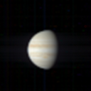
QUOTE (DonPMitchell @ Sep 16 2006, 08:01 PM)  I hope you don't feel I am being discouraging. Not at all. There's generally just too much "mystique" about gamma that I rather not mess around with it. Here's a literal implementation of a 1/2.2 power function in the code: 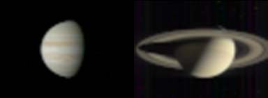 The above shows nicely why I'm not too fond of gamma manipulations -- the terminator comes out too sharp (you don't get the feeling Jupiter is actually 3D), the colors and contrast are bleached, and it also brings out an ever-present non-dark background. Hmm... or maybe that means I have to calibrate my monitor... Here's that Saturn mosaic again:
-------------------- |
|
|
|
|
|
| Guest_DonPMitchell_* |
Sep 17 2006, 04:17 AM
Post
#4
|
|
Guests |
QUOTE (ugordan @ Sep 16 2006, 02:37 PM) Here's a literal implementation of a 1/2.2 power function in the code: The real-life scene is probably not as saturated with color as a lot of photos show. Your gamma 2.2 images don't look like anything is going wrong in the software at all. I thought perhaps you were seeing something way off. |
|
|
|
|
Sep 17 2006, 04:44 PM
Post
#5
|
||||||
|
Senior Member Group: Members Posts: 3648 Joined: 1-October 05 From: Croatia Member No.: 523 |
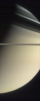
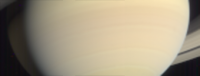
A couple of rough Saturn mosaics:
The blob in the middle image is Tethys. Ring mosaics:
All images magnified 2x and gamma-corrected. -------------------- |
|||||
|
|
|
|||||
|
Sep 17 2006, 07:17 PM
Post
#6
|
|
 Member Group: Members Posts: 241 Joined: 22-August 05 From: Stockholm Sweden Member No.: 468 |
I think it looks great. Very subtle beautiful colors.
Keep em coming! /M |
|
|
|
|
Sep 19 2006, 05:21 PM
Post
#7
|
|
|
Senior Member Group: Members Posts: 3648 Joined: 1-October 05 From: Croatia Member No.: 523 |
A few Jupiter images, fixed the greenish hue. It was due to my code subtracting out dark background when apparently it was already subtracted from the Jupiter flyby cubes.
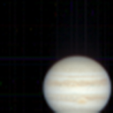  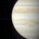 The middle and right image were taken not far apart, the rightmost image is much bigger because it utilized a high-resolution mode developed in-flight, it increases the spatial resolution by 3x at a cost of lowering the S/N ratio a bit. The leftmost image is also hi-res, but was taken far before closest approach. Outbound crescent, 2 cube mosaic: 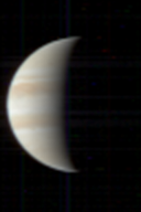 A couple of Europa transits: 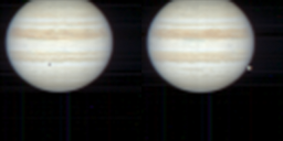 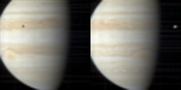 It's a shame the transit on the right didn't catch more area to the left of Jupiter's limb, there was a great grouping of Io and Ganymede there. The rightmost image is actually very close in time to an ISS narrow-angle sequence, taken on January 2nd, 2001. Again, all images magnified 2x and gamma-corrected. -------------------- |
|
|
|
|
Sep 19 2006, 07:23 PM
Post
#8
|
|
|
Member Group: Members Posts: 241 Joined: 22-August 05 From: Stockholm Sweden Member No.: 468 |
QUOTE (ugordan @ Sep 19 2006, 07:21 PM) A few Jupiter images, fixed the greenish hue. It was due to my code subtracting out dark background when apparently it was already subtracted from the Jupiter flyby cubes. Just for the sake of inconsistensy  I think it looks great. Fantastic actually. If i had to pick on something i would have to mention the almost invisible residual pattern in the images. faint thin horizontal and vertical lines. some of them seem to show up at the same place in all the images. (sometimes rotated 90 degrees but i guess thats you rotating the images for display) others seem more random. is this due to sensor sensitivity variation and/or does it have to do with the scanning process of the instrument? Do you write your image processing software for some standard platform (IDL or something) or do you write totally standalone code? /M |
|
|
|
|
Sep 19 2006, 07:37 PM
Post
#9
|
|
|
Senior Member Group: Members Posts: 3648 Joined: 1-October 05 From: Croatia Member No.: 523 |
The vertical stripes (most noticeable is a blue line) in some darker shots... I've checked and double-checked the flatfields and dark background removal code and none of them even touches that. There's a load of them in the raw data, they appear to be static so those are probably hot pixels on the CCD. Since the cubes are readout one line at a time, in a push-broom mode with the spectra of the line being split in the vertical dimension, It means same samples in all lines in a given spectral band will suffer from the same problem. Hence the vertical lines. What I don't understand is why adequate flatfields/dark current models haven't been produced to deal with this. This only affects the visible channel, the IR channel seems fine (note the VIS and IR channels are actually two different physical parts). So far, there's nothing I can do about it.
The code is an ad-hoc implementation in C, it's rudimentary and messy as I progressively modified it from simply trying to read the cubes to do more complex stuff like color matching. It doesn't even output a nice PNG color image, but a raw 64x64 pixel dump with 3 interleaved rgb channels 
-------------------- |
|
|
|
|
Sep 19 2006, 08:16 PM
Post
#10
|
|
|
Member Group: Members Posts: 241 Joined: 22-August 05 From: Stockholm Sweden Member No.: 468 |
I guess you have to make an additional flatfield removal using a homebrewn flatfield. Try simply takeing one row of an image of black space, scale to width of image and remove it from the data and see what it looks like.
/M |
|
|
|
|
Sep 20 2006, 07:24 AM
Post
#11
|
|
|
Senior Member Group: Members Posts: 3648 Joined: 1-October 05 From: Croatia Member No.: 523 |
QUOTE (Malmer @ Sep 19 2006, 09:16 PM) I guess you have to make an additional flatfield removal using a homebrewn flatfield. Try simply takeing one row of an image of black space, scale to width of image and remove it from the data and see what it looks like. I don't think it's a flatfield problem. Flatfields only correct for varying sensitivity of different pixels. This appears to be primarily a dark current problem - you can see the lines even in dark space which flatfields can't remove. Remember, you divide or multiply the image with a flatfield. This, on the other hand, will obviously need subtracting out. I don't even know where to begin modelling dark current data. The provided dark current model uses a two-parameter table, one a standalone part and the other a variable part multiplied by exposure, for each CCD pixel. The model seems fine for normal resolution cubes (though even that doesn't completely remove everything), but the hi-res one seems buggy. Furthermore, these Jupiter images where the dark was subtracted by the instrument itself show no apparent signs of those nasty lines. Then again, this could be due to the fact Jupiter images took a 4 times shorter exposure than Saturn targets, because of increased light levels there so dark current didn't have as much time to build up. A document on the PDS says new models are generated every month or so, but it looks to me the same tables appear on all 8 VIMS DVDs. I mailed one of the guys responsible for the PDS volumes so we'll see what they have to say. -------------------- |
|
|
|
|
Sep 20 2006, 08:48 AM
Post
#12
|
|
|
Member Group: Members Posts: 241 Joined: 22-August 05 From: Stockholm Sweden Member No.: 468 |
it was a typo. i actually ment darkcurrent. mixed them up in my head for some reason. (thats why i suggested you to use a bit of black space to serve as a DC remover)
|
|
|
|
|
Sep 20 2006, 09:22 AM
Post
#13
|
|
|
Senior Member Group: Members Posts: 3648 Joined: 1-October 05 From: Croatia Member No.: 523 |
Although the noise stays fixed, it changes intensity -- it's likely connected with exposure duration. It's not likely to be as easy as subtracting a generic dark cube from all cubes. I don't think a small bit of dark space would do the trick as there's also a fair bit of cosmic ray noise induced. It would be required to average many dark lines. There are many dark space cubes that weren't even readout as a full 64 width swath so they're of limited usefulness. Additionally, the physical resolution of the CCD is AFAIK 192x96 pixels with 192 being one spatial line and 96 being the visible spectral channels. All cubes have a maximum resolution of 64 spatial pixels. Normal mode of operation simply sums three pixels in a line to get 192/3=64 pixels. The high res mode, however doesn't sum the individual pixels and that's where the 3x resoulution increase comes from. This is where it gets complicated a bit: which 64 pixels out of 192 will be readout depends upon the offset factors and is somewhat clumsy. A fair bit of margin for error is present if you don't know exactly what you're doing. The PDS document isn't all too clear on certain aspects.
Which brings me to the point -- if this is as simple as we suggest, why didn't the VIMS folks do this in the first place? This noise problem must have been known at least since Saturn orbit insertion. IMHO, it's not up to us to fix the calibration and produce our own files that do basic stuff like dark current removal. Of course, all this is barring I haven't screwed up in my code somewhere, but I'm more and more certain that's not the case. -------------------- |
|
|
|
|
Sep 20 2006, 11:34 AM
Post
#14
|
|
|
Senior Member Group: Members Posts: 3648 Joined: 1-October 05 From: Croatia Member No.: 523 |
Not particularly related to my processing, but here are a couple of past releases by the VIMS team of Jupiter results and Titan results. The Jupiter page shows the same image as my bottom 2nd image from the right. Their image was mirrored left-right as Cassini never saw Jupiter from that vantage point. The dark spot on Jupiter's disc is not Io's shadow as they suggest, it's Europa. They used a simple 3-channel RGB composite, but it's notable there's some vertical banding present in their data as well. This is not the same noise we were discussing here, though. It's more likely artifacts during the scanning mirror uneven movement and different lines were unevenly exposed hence the brightness gradient.
The Titan page I bring up because it does show the ugly vertical lines -- note the false color composite labeled "VIS channel". Seems they were unable to remove it as well. -------------------- |
|
|
|
 ugordan Processing VIMS cubes Sep 10 2006, 07:51 PM
 Malmer its a really great "realitycheck" for th... Sep 12 2006, 09:48 PM
 ugordan QUOTE (Malmer @ Sep 12 2006, 10:48 PM) it... Sep 13 2006, 08:56 AM Malmer QUOTE (ugordan @ Sep 13 2006, 10:56 AM) I... Sep 13 2006, 03:04 PM dilo Very nice work, gordan... now we see the colors... Sep 12 2006, 10:21 PM ugordan QUOTE (dilo @ Sep 12 2006, 11:21 PM) To m... Sep 13 2006, 06:56 AM dilo QUOTE (ugordan @ Sep 13 2006, 06:56 AM) T... Sep 13 2006, 04:17 PM CAP-Team It looks as if the colors match Voyager's colo... Sep 13 2006, 02:16 PM Malmer QUOTE (ugordan @ Sep 10 2006, 09:51 PM) I... Sep 13 2006, 02:49 PM DonPMitchell How do you convert XYZ to RGB? Are you making sRG... Sep 13 2006, 04:55 PM ugordan Yes, I'm using that XYZ to RGB matrix. I had t... Sep 13 2006, 08:33 PM DonPMitchell Very good. Gamma 2.2 is technically what should b... Sep 14 2006, 04:07 AM ugordan The pixels are linear as far as I know, a 12 bit A... Sep 14 2006, 07:09 AM Malmer QUOTE (DonPMitchell @ Sep 14 2006, 06:07 ... Sep 14 2006, 09:30 AM Malmer The pixels in the ISS images are not linearly save... Sep 14 2006, 09:43 AM ugordan I am very well aware of the ISS data specifics. Wh... Sep 14 2006, 10:47 AM Malmer QUOTE (ugordan @ Sep 14 2006, 12:47 PM) I... Sep 15 2006, 12:50 PM ugordan QUOTE (Malmer @ Sep 15 2006, 01:50 PM) On... Sep 15 2006, 06:26 PM Malmer it would be fun to paint spheres in the colors you... Sep 15 2006, 11:40 PM DonPMitchell QUOTE (Malmer @ Sep 14 2006, 02:30 AM) co... Sep 14 2006, 03:39 PM Malmer I think the strange piecewise funktion has its ben... Sep 15 2006, 12:33 PM ugordan QUOTE (Malmer @ Sep 15 2006, 01:33 PM) I ... Sep 15 2006, 06:10 PM DonPMitchell One concept is to make an image that resembles wha... Sep 16 2006, 01:56 AM Malmer QUOTE (DonPMitchell @ Sep 16 2006, 03:56 ... Sep 16 2006, 09:42 AM ugordan A mosaic of Saturn's northern latitudes:
App... Sep 16 2006, 03:39 PM john_s Just checked out your gallery, ugordan- your proce... Sep 16 2006, 04:54 PM ugordan QUOTE (john_s @ Sep 16 2006, 05:54 PM) Ju... Sep 16 2006, 05:56 PM DonPMitchell QUOTE (Malmer @ Sep 16 2006, 02:42 AM) so... Sep 16 2006, 06:47 PM Malmer QUOTE (DonPMitchell @ Sep 16 2006, 08:47 ... Sep 16 2006, 09:02 PM Malmer QUOTE (ugordan @ Sep 20 2006, 11:22 AM) W... Sep 20 2006, 03:23 PM ugordan Here are a couple of... hm... questionable(?) resu... Sep 20 2006, 07:38 PM tedstryk Great work! As for the calibration data, it c... Sep 19 2006, 08:18 PM slinted UGordon, first off, this is an amazing project you... Sep 20 2006, 11:00 PM ugordan Thanks, Slinted! I'll certainly have a loo... Sep 21 2006, 07:46 AM JRehling QUOTE (ugordan @ Sep 21 2006, 12:46 AM) I... Sep 21 2006, 06:06 PM ugordan JRehling, those are all valid, good points. I said... Sep 21 2006, 07:16 PM DonPMitchell It is true that Judd and Vos made improvements to ... Sep 21 2006, 12:55 PM ugordan QUOTE (DonPMitchell @ Sep 21 2006, 01:55 ... Sep 21 2006, 02:25 PM DonPMitchell Reflectance is independant of the illuminant. It ... Sep 21 2006, 02:43 PM DonPMitchell
There's a brown Moon for you, taken by Galil... Sep 21 2006, 07:03 PM slinted Good points made by all,
Part of my confusion on... Sep 21 2006, 08:52 PM ugordan VIMS cubes, their raw form, capture the brightness... Sep 21 2006, 09:14 PM JRehling QUOTE (slinted @ Sep 21 2006, 01:52 PM) I... Sep 21 2006, 10:32 PM ugordan QUOTE (JRehling @ Sep 21 2006, 11:32 PM) ... Sep 22 2006, 08:07 AM ugordan I can understand the reasoning of not touching the... Sep 22 2006, 06:41 PM DonPMitchell QUOTE (ugordan @ Sep 22 2006, 11:41 AM) Y... Sep 22 2006, 07:06 PM ugordan Be my guest. For starters, here's a dump of th... Sep 22 2006, 07:45 PM tedstryk For Jupiter and Saturn, I am biased toward the rig... Sep 22 2006, 09:12 PM ugordan I've been experimenting with cleaning up the V... Sep 25 2006, 08:02 PM ugordan Sure enough, I got a response from the VIMS team. ... Sep 26 2006, 07:33 AM edstrick It probably boils down to too-much-to-do, not-enou... Sep 26 2006, 09:49 AM ugordan To reiterate what you said, on my asking if update... Sep 26 2006, 02:27 PM ugordan Here are a few quick results from the new PDS rele... Oct 4 2006, 05:55 PM Indian3000 First test to process VIMS cube ( gamma 2.2 )
v1... Oct 11 2006, 11:53 AM elakdawalla Hey folks, the Rings Node has generated preview im... Feb 18 2011, 10:20 PM ngunn A superb piece of work at TPS but we have to have ... Apr 28 2011, 09:27 PM
ugordan QUOTE (Malmer @ Sep 12 2006, 10:48 PM) it... Sep 13 2006, 08:56 AM Malmer QUOTE (ugordan @ Sep 13 2006, 10:56 AM) I... Sep 13 2006, 03:04 PM dilo Very nice work, gordan... now we see the colors... Sep 12 2006, 10:21 PM ugordan QUOTE (dilo @ Sep 12 2006, 11:21 PM) To m... Sep 13 2006, 06:56 AM dilo QUOTE (ugordan @ Sep 13 2006, 06:56 AM) T... Sep 13 2006, 04:17 PM CAP-Team It looks as if the colors match Voyager's colo... Sep 13 2006, 02:16 PM Malmer QUOTE (ugordan @ Sep 10 2006, 09:51 PM) I... Sep 13 2006, 02:49 PM DonPMitchell How do you convert XYZ to RGB? Are you making sRG... Sep 13 2006, 04:55 PM ugordan Yes, I'm using that XYZ to RGB matrix. I had t... Sep 13 2006, 08:33 PM DonPMitchell Very good. Gamma 2.2 is technically what should b... Sep 14 2006, 04:07 AM ugordan The pixels are linear as far as I know, a 12 bit A... Sep 14 2006, 07:09 AM Malmer QUOTE (DonPMitchell @ Sep 14 2006, 06:07 ... Sep 14 2006, 09:30 AM Malmer The pixels in the ISS images are not linearly save... Sep 14 2006, 09:43 AM ugordan I am very well aware of the ISS data specifics. Wh... Sep 14 2006, 10:47 AM Malmer QUOTE (ugordan @ Sep 14 2006, 12:47 PM) I... Sep 15 2006, 12:50 PM ugordan QUOTE (Malmer @ Sep 15 2006, 01:50 PM) On... Sep 15 2006, 06:26 PM Malmer it would be fun to paint spheres in the colors you... Sep 15 2006, 11:40 PM DonPMitchell QUOTE (Malmer @ Sep 14 2006, 02:30 AM) co... Sep 14 2006, 03:39 PM Malmer I think the strange piecewise funktion has its ben... Sep 15 2006, 12:33 PM ugordan QUOTE (Malmer @ Sep 15 2006, 01:33 PM) I ... Sep 15 2006, 06:10 PM DonPMitchell One concept is to make an image that resembles wha... Sep 16 2006, 01:56 AM Malmer QUOTE (DonPMitchell @ Sep 16 2006, 03:56 ... Sep 16 2006, 09:42 AM ugordan A mosaic of Saturn's northern latitudes:
App... Sep 16 2006, 03:39 PM john_s Just checked out your gallery, ugordan- your proce... Sep 16 2006, 04:54 PM ugordan QUOTE (john_s @ Sep 16 2006, 05:54 PM) Ju... Sep 16 2006, 05:56 PM DonPMitchell QUOTE (Malmer @ Sep 16 2006, 02:42 AM) so... Sep 16 2006, 06:47 PM Malmer QUOTE (DonPMitchell @ Sep 16 2006, 08:47 ... Sep 16 2006, 09:02 PM Malmer QUOTE (ugordan @ Sep 20 2006, 11:22 AM) W... Sep 20 2006, 03:23 PM ugordan Here are a couple of... hm... questionable(?) resu... Sep 20 2006, 07:38 PM tedstryk Great work! As for the calibration data, it c... Sep 19 2006, 08:18 PM slinted UGordon, first off, this is an amazing project you... Sep 20 2006, 11:00 PM ugordan Thanks, Slinted! I'll certainly have a loo... Sep 21 2006, 07:46 AM JRehling QUOTE (ugordan @ Sep 21 2006, 12:46 AM) I... Sep 21 2006, 06:06 PM ugordan JRehling, those are all valid, good points. I said... Sep 21 2006, 07:16 PM DonPMitchell It is true that Judd and Vos made improvements to ... Sep 21 2006, 12:55 PM ugordan QUOTE (DonPMitchell @ Sep 21 2006, 01:55 ... Sep 21 2006, 02:25 PM DonPMitchell Reflectance is independant of the illuminant. It ... Sep 21 2006, 02:43 PM DonPMitchell
There's a brown Moon for you, taken by Galil... Sep 21 2006, 07:03 PM slinted Good points made by all,
Part of my confusion on... Sep 21 2006, 08:52 PM ugordan VIMS cubes, their raw form, capture the brightness... Sep 21 2006, 09:14 PM JRehling QUOTE (slinted @ Sep 21 2006, 01:52 PM) I... Sep 21 2006, 10:32 PM ugordan QUOTE (JRehling @ Sep 21 2006, 11:32 PM) ... Sep 22 2006, 08:07 AM ugordan I can understand the reasoning of not touching the... Sep 22 2006, 06:41 PM DonPMitchell QUOTE (ugordan @ Sep 22 2006, 11:41 AM) Y... Sep 22 2006, 07:06 PM ugordan Be my guest. For starters, here's a dump of th... Sep 22 2006, 07:45 PM tedstryk For Jupiter and Saturn, I am biased toward the rig... Sep 22 2006, 09:12 PM ugordan I've been experimenting with cleaning up the V... Sep 25 2006, 08:02 PM ugordan Sure enough, I got a response from the VIMS team. ... Sep 26 2006, 07:33 AM edstrick It probably boils down to too-much-to-do, not-enou... Sep 26 2006, 09:49 AM ugordan To reiterate what you said, on my asking if update... Sep 26 2006, 02:27 PM ugordan Here are a few quick results from the new PDS rele... Oct 4 2006, 05:55 PM Indian3000 First test to process VIMS cube ( gamma 2.2 )
v1... Oct 11 2006, 11:53 AM elakdawalla Hey folks, the Rings Node has generated preview im... Feb 18 2011, 10:20 PM ngunn A superb piece of work at TPS but we have to have ... Apr 28 2011, 09:27 PM |

|
Lo-Fi Version | Time is now: 26th September 2024 - 10:19 AM |
|
RULES AND GUIDELINES Please read the Forum Rules and Guidelines before posting. IMAGE COPYRIGHT |
OPINIONS AND MODERATION Opinions expressed on UnmannedSpaceflight.com are those of the individual posters and do not necessarily reflect the opinions of UnmannedSpaceflight.com or The Planetary Society. The all-volunteer UnmannedSpaceflight.com moderation team is wholly independent of The Planetary Society. The Planetary Society has no influence over decisions made by the UnmannedSpaceflight.com moderators. |
SUPPORT THE FORUM Unmannedspaceflight.com is funded by the Planetary Society. Please consider supporting our work and many other projects by donating to the Society or becoming a member. |
|