Ground-based image reduction in support of Juno |

  |
Ground-based image reduction in support of Juno |
 Dec 9 2016, 04:09 PM Dec 9 2016, 04:09 PM
Post
#1
|
|
 Newbie  Group: Members Posts: 7 Joined: 9-December 16 From: University of Leicester Member No.: 8085 |
Hello everyone,
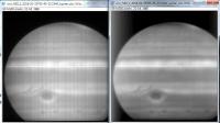
I am a postgraduate researcher studying the climate variability of Jupiter during the Juno mission. This involves analysis and comparison of ground-based observations taken from the Very Large Telescope (VLT) in Chile and data, to be used at a later date, from Juno, with ground-based observations corresponding with perijoves of the spacecraft. My first project has been working on reducing images taken by the VISIR mid-infrared instrument (operating range between 5 and 20 microns) on the VLT (more details found below). As a result of new AQUARIUS detector (installed 2016) on VISIR, there is a pattern that plagues all of the images. This pattern causes problems with data retrieval (getting useful information about temperature and composition of the atmosphere) and is also not very nice aesthetically and not entirely suitable for publication. The current technique for reducing this data and removing the lines works fine aesthetically, however it uses the program GiMP. This means that although it fixes the problem, it does so by smoothing or in-painting in ways that aren't truly scientific. Pixel values will be changed and information will be introduced or lost such that it actually affects the science output from the observations. I have provided the link to a public google drive folder containing some of the raw images as a sample of what we are dealing with, I can provide more if necessary. From my (limited) knowledge of programming (Python and IDL) I have been able to remove the central horizontal stripe, but the vertical stripes remain (although the images attached do not show this as they are purely raw images directly from the observatory). If anyone has experience with removing detector patterns and any pattern like this or can recommend some techniques to try it would be greatly appreciated! ESO - VISIR instrument: http://www.eso.org/sci/facilities/paranal/...ents/visir.html Google drive folder: https://drive.google.com/open?id=0B8_Ynti1o...M3hjS3dWal83X28 edit: fixed the links -------------------------------------------------------------------------------------------------- Thank you, Padraig Donnelly DISCLAIMER: All images provided are taken from the VLT in Chile and are fully credited to the European Southern Observatory (ESO). |
 |
 
|
|
Dec 9 2016, 06:04 PM
Post
#2
|
|
|
Senior Member Group: Members Posts: 2542 Joined: 13-September 05 Member No.: 497 |
QUOTE (PTDonnelly @ Dec 9 2016, 08:09 AM)  If anyone has experience with removing detector patterns... Do you have any flat fields? Is this a fixed pattern? If it is fixed, then this is detector 101 stuff. If it's not fixed, then your electronics is broken  -------------------- Disclaimer: This post is based on public information only. Any opinions are my own.
|
|
|
|
|
Dec 9 2016, 08:37 PM
Post
#3
|
|
|
Newbie Group: Members Posts: 7 Joined: 9-December 16 From: University of Leicester Member No.: 8085 |
QUOTE (mcaplinger @ Dec 9 2016, 06:04 PM) Do you have any flat fields? Is this a fixed pattern? If it is fixed, then this is detector 101 stuff. If it's not fixed, then your electronics is broken Yes it is fixed and I am working on getting the flat fields. Also it's the 'detector 101' stuff that I want to know! |
|
|
|
|
Dec 9 2016, 10:38 PM
Post
#4
|
||
 Member Group: Members Posts: 796 Joined: 27-February 08 From: Heart of Europe Member No.: 4057 |
If flat field doesn't work you can try some process for non-uniformity removal.
Here is quick and dirty example via bandpass filtering in FIJI.
Attached thumbnail(s)
-------------------- |
|
|
|
|
|
|
Dec 9 2016, 11:43 PM
Post
#5
|
||||
|
Senior Member Group: Members Posts: 2346 Joined: 7-December 12 Member No.: 6780 |
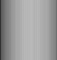
If no official flatfield is available, you may alternatively calculate your own flatfield. In this case, the upper and the lower half of the image seem to need two different essentially 1-dimensional flatfields.
Here a quick&dirty approach based on machi's screenshot of the raw: Crop the upper part of the lower half:
calculate vertical averages only, and stretch it over the required height, in this example the whole height of the source image, but a better solution would be a separate treatment for the upper half:
Usually divide by the flatfield. As an approximation, I've averaged with the negative of the flatfield, and stretched brightness:
The advantage with respect to bandpassing is conservation of high-frequency image components. This includes other instrument artifacts. |
|||
|
|
|
|||
|
Dec 9 2016, 11:52 PM
Post
#6
|
|
|
Member Group: Members Posts: 122 Joined: 26-June 04 From: Austria Member No.: 89 |
The software "Topaz Denoise" include a debanding feature.
But if you could find the real flatfield data this should be at first used to get calibration right before you try other techniques. Robert |
|
|
|
|
Dec 10 2016, 05:41 AM
Post
#7
|
|
|
Senior Member Group: Members Posts: 2542 Joined: 13-September 05 Member No.: 497 |
QUOTE (PTDonnelly @ Dec 9 2016, 12:37 PM) Also it's the 'detector 101' stuff that I want to know! It would surprise me if there wasn't a local expert at VLT who has tools to deal with the specifics of this instrument. For IR cameras, if you have a flat field at one scene temperature you can just subtract that from all scenes -- so-called "one point correction". If you have two flats at two different scene temps, you can produce a multiplicative correction by taking the ratio of the two flats and an subtractive correction with the colder flat ("two-point correction"). Usually individual bad pixels have to be mapped and then interpolated over, although running a 3x3 median filter over the image can often be good enough. -------------------- Disclaimer: This post is based on public information only. Any opinions are my own.
|
|
|
|
|
Dec 10 2016, 11:57 AM
Post
#8
|
|
|
Senior Member Group: Members Posts: 2346 Joined: 7-December 12 Member No.: 6780 |
Since you seem to work at the University of Leicester, and Leigh Fletcher is working Juno and Jupiter-related, too, he might find time to give you some specific advice.
|
|
|
|
|
Dec 10 2016, 07:18 PM
Post
#9
|
|
|
Member Group: Members Posts: 890 Joined: 18-November 08 Member No.: 4489 |
i use the terminal version of Gmic ( there is a gimp plugin ) to inpaint some things , it uses a heat flow pde .
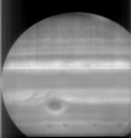
? scientifically accurate ? for vertical or horizontal noise i tend to use ISIS3 and the "dstripe" tool a( 73x1,1x73 ) boxcars  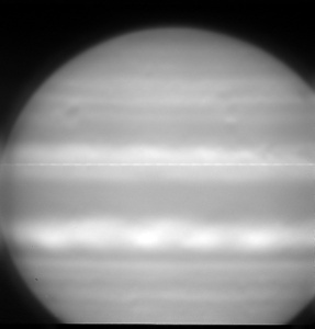 isis3 "cubenorm" 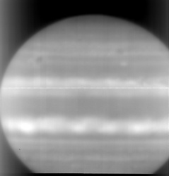
|
|
|
|
|
Dec 11 2016, 01:53 PM
Post
#10
|
|
|
Newbie Group: Members Posts: 7 Joined: 9-December 16 From: University of Leicester Member No.: 8085 |
QUOTE (Gerald @ Dec 10 2016, 11:57 AM) Since you seem to work at the University of Leicester, and Leigh Fletcher is working Juno and Jupiter-related, too, he might find time to give you some specific advice. He is my supervisor and the one who gave me this job! |
|
|
|
|
Dec 11 2016, 01:55 PM
Post
#11
|
|
|
Newbie Group: Members Posts: 7 Joined: 9-December 16 From: University of Leicester Member No.: 8085 |
QUOTE (Gerald @ Dec 9 2016, 11:43 PM) If no official flatfield is available, you may alternatively calculate your own flatfield. In this case, the upper and the lower half of the image seem to need two different essentially 1-dimensional flatfields. Here a quick&dirty approach based on machi's screenshot of the raw: Crop the upper part of the lower half: [image] calculate vertical averages only, and stretch it over the required height, in this example the whole height of the source image, but a better solution would be a separate treatment for the upper half: [image] Usually divide by the flatfield. As an approximation, I've averaged with the negative of the flatfield, and stretched brightness: [image] The advantage with respect to bandpassing is conservation of high-frequency image components. This includes other instrument artifacts. This could be a decent approach with some things, however you do lose some latitudinal variation within the belt/zone structure by doing this. |
|
|
|
|
Dec 11 2016, 01:57 PM
Post
#12
|
|
|
Newbie Group: Members Posts: 7 Joined: 9-December 16 From: University of Leicester Member No.: 8085 |
QUOTE (JohnVV @ Dec 10 2016, 07:18 PM) i use the terminal version of Gmic ( there is a gimp plugin ) to inpaint some things , it uses a heat flow pde . ? scientifically accurate ? for vertical or horizontal noise i tend to use ISIS3 and the "dstripe" tool a 73x1 and 1x73 boxcar [image] [image] isis3 "cubenorm" [image] Unfortunately, much like using a high-n 'n*n' fliter, you lose a lot of the important wave and weather structures though excessive smoothing. |
|
|
|
|
Dec 11 2016, 01:59 PM
Post
#13
|
|
|
Newbie Group: Members Posts: 7 Joined: 9-December 16 From: University of Leicester Member No.: 8085 |
QUOTE (mcaplinger @ Dec 10 2016, 05:41 AM) It would surprise me if there wasn't a local expert at VLT who has tools to deal with the specifics of this instrument. For IR cameras, if you have a flat field at one scene temperature you can just subtract that from all scenes -- so-called "one point correction". If you have two flats at two different scene temps, you can produce a multiplicative correction by taking the ratio of the two flats and an subtractive correction with the colder flat ("two-point correction"). Usually individual bad pixels have to be mapped and then interpolated over, although running a 3x3 median filter over the image can often be good enough. I have tried to get in contact with operators at the VLT directly, but to no avail as of yet. I do want to try the flat fields and I am currently trying to get the ones from this observation run. I will try the technique you mention, thanks. |
|
|
|
|
Dec 13 2016, 11:59 PM
Post
#14
|
||
 IMG to PNG GOD Group: Moderator Posts: 2254 Joined: 19-February 04 From: Near fire and ice Member No.: 38 |
As others have indicated, flat fields and/or some instrument-specific processing should be possible. The problem currently seems to be lack of information.
Without more information/data, it is necessary either to attempt to construct a flat field (as suggested above by Gerald) or somehow to digitally filter the image in an attempt to remove the artifacts. Below is an image (the same one as used above by JohnVV) that has been destriped several times using different stripe widths. This is comparable to what the ISIS program dstripe does. The destriping can result in minor loss of real details but in this case the loss of details isn't very obvious.
|
|
|
|
|
|
|

|
Lo-Fi Version | Time is now: 24th September 2024 - 10:22 AM |
|
RULES AND GUIDELINES Please read the Forum Rules and Guidelines before posting. IMAGE COPYRIGHT |
OPINIONS AND MODERATION Opinions expressed on UnmannedSpaceflight.com are those of the individual posters and do not necessarily reflect the opinions of UnmannedSpaceflight.com or The Planetary Society. The all-volunteer UnmannedSpaceflight.com moderation team is wholly independent of The Planetary Society. The Planetary Society has no influence over decisions made by the UnmannedSpaceflight.com moderators. |
SUPPORT THE FORUM Unmannedspaceflight.com is funded by the Planetary Society. Please consider supporting our work and many other projects by donating to the Society or becoming a member. |
|