Juno PDS data |

  |
Juno PDS data |
 Jun 28 2016, 07:11 AM Jun 28 2016, 07:11 AM
Post
#16
|
|
 Member  Group: Members Posts: 238 Joined: 15-January 13 Member No.: 6842 |
QUOTE (mcaplinger @ Jun 27 2016, 06:49 PM)  We didn't take any RGB images of stars and the zodiacal light. I see. Emily's page gave me an impression that you did, with headers like: QUOTE 2013107_00C048 Filters: BGR I used IMG2PNG to create JNCE_2013107_00C048_V01.png but as I don't know much about processing such images, I got a black stip with barely a hint of what looks like noise. And I also don't know how to combine that raw imagery into an RGB composite. -------------------- Curiosity rover panoramas: http://www.facebook.com/CuriosityRoverPanoramas
My Photosynth panoramas: http://photosynth.net/userprofilepage.aspx...;content=Synths |
 |
 
|
|
Jun 28 2016, 12:14 PM
Post
#17
|
|||
|
Senior Member Group: Members Posts: 2346 Joined: 7-December 12 Member No.: 6780 |
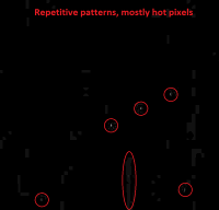
This is a 16-fold brightness-stretched and 2-fold enlarged crop of 2013107_00C048:
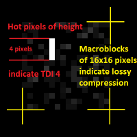
It shows one copy of a pattern which repeats each 3x128=384 pixel rows in the raw swath. Those repetitive patterns are mostly caused by hot pixels. But there exist some repetitive spots of different type, too. The 3x128 pixels are resulting from exposures made of three color bands times 128 pixels framelet height. This is a 16-fold enlarged crop:
It shows a vertical line of 4 bright pixels. This line is the result of one hot pixel on the CCD copied 4-times by the TDI mechanism. It indicates, that 4 TDI steps have been applied for this image. - TDI 4 is hard for finding many stars. TDI 64 and TDI 80 are much better-suited for this purpose. The 16x16 noisy block indicates, that the image has been compressed lossily on macroblocks (tiles) of 16x16 pixels. When looking for real objects, first mark all repetitive patterns, or clean the image from these patterns. Then decompose the swath into framelets of height 128 pixels, grouped into exposures of 3 framelets. Insert a gap of 27 pixels between neighbouring framelets within one exposure. Assign a color channel to each framelet within each exposure. Shift the exposures vertically, until you get a match of corresponding features (about 114 pixels, give or take a few). Use the valid color channel of each exposure to obtain full rgb coverage. The result will be a first draft of an RGB image. I'd recommend to use 2013282_000C91 (aka EFB01), showing Earth's moon, as a first exercise. The first 22 slides of the pdf I've provided a few weeks ago should apply to moon and star RGB images, as well. Spacecraft trajectory and rotation of the target objects can be neglected for distant targets. You may use weights for the colors in order to adjust the raw colors, if you use EDRs; the weights for the colors are likely to undergo refined calibration. |
||
|
|
|
||
|
Jun 28 2016, 02:16 PM
Post
#18
|
|
|
Senior Member Group: Members Posts: 2517 Joined: 13-September 05 Member No.: 497 |
QUOTE (Gerald @ Jun 28 2016, 04:14 AM) This is a 16-fold brightness-stretched and 2-fold enlarged crop of 2013107_00C048: This particular image was part of a mapping operations test. Since it has a short exposure, it likely doesn't show any real objects, just noise. -------------------- Disclaimer: This post is based on public information only. Any opinions are my own.
|
|
|
|
|
Jul 2 2016, 03:33 AM
Post
#19
|
|
|
Newbie Group: Members Posts: 1 Joined: 17-June 16 Member No.: 7982 |
QUOTE (wildespace @ Jun 27 2016, 04:59 AM) I don't know how to work with IMG files (they won't even mount on a virtual drive on my laptop), so could someone please post JunoCam's RGB images of stars and the zodaical light? Information about the exposure for those images would be appreciated too. Thanks  Hi, I've been working to load and process .IMG file using Octave / MATLAB scripts. Take a look to https://javierluiso.wordpress.com/, I hope my work will be useful to you. Javier |
|
|
|
|
Jul 2 2016, 07:13 PM
Post
#20
|
|
|
Member Group: Members Posts: 890 Joined: 18-November 08 Member No.: 4489 |
any reason you are not opining img files as a raw whit a header
or using img2png or using isis3 or using vicar or using ??? now Juno data is a bit odd and needs a lot of processing |
|
|
|
|
Jul 2 2016, 08:47 PM
Post
#21
|
|
|
Senior Member Group: Members Posts: 2346 Joined: 7-December 12 Member No.: 6780 |
Reading the IMGs is just the first small hurdle. The IMGs are raw binary data streams without an embedded header. More important is opening the files in a tool or with a computer language you're used to, and which is sufficiently powerful to perform the sophisticated processing.
|
|
|
|
|
Jul 2 2016, 09:05 PM
Post
#22
|
|
|
Senior Member Group: Members Posts: 2517 Joined: 13-September 05 Member No.: 497 |
QUOTE (Gerald @ Jul 2 2016, 12:47 PM) The IMGs are raw binary data streams without an embedded header. "raw binary data streams"? They're just normal 2D images, in row-major order, with 8 or 16-bit pixels. You could load them raw into Photoshop if you read the image dimensions out of the label manually. Unpacking the framelets might be a bit of a challenge, but we do that for you with the image releases that have actual content, like EFB. Most simple manipulations are a few lines of code in any modern processing environment. -------------------- Disclaimer: This post is based on public information only. Any opinions are my own.
|
|
|
|
|
Jul 3 2016, 06:25 AM
Post
#23
|
|
|
Senior Member Group: Members Posts: 2346 Joined: 7-December 12 Member No.: 6780 |
To me, the most easy file format to handle is the EDR IMG format, as provided in the MSSS PDS. But I can't assess, whether I'm representative.
Essential for fast and good results is early accessibility to these files. But I can handle the RDRs, too. If intermediately processed images will be the only available, I might need to reconstruct the EDRs as far as possible. |
|
|
|
|
Mar 8 2017, 04:05 AM
Post
#24
|
|
|
Senior Member Group: Members Posts: 2346 Joined: 7-December 12 Member No.: 6780 |
Juno PDS Imaging Node is online.
|
|
|
|
|
Jun 27 2017, 10:54 PM
Post
#25
|
|
 Administrator Group: Admin Posts: 5172 Joined: 4-August 05 From: Pasadena, CA, USA, Earth Member No.: 454 |
-------------------- My website - My Patreon - @elakdawalla on Twitter - Please support unmannedspaceflight.com by donating here.
|
|
|
|
|
Aug 26 2017, 01:07 AM
Post
#26
|
|
 IMG to PNG GOD Group: Moderator Posts: 2251 Joined: 19-February 04 From: Near fire and ice Member No.: 38 |
Today when starting work on some additional Juno images after a hiatus of several weeks, I noticed that new versions are available of some important instrument/frame SPICE kernels. This is of importance for everyone using SPICE data for JunoCam processing. In particular the new version of the JunoCam instrument kernel is interesting; among other things it contains this note:
QUOTE ...there is a fixed bias of 61.88 msec in the start time with a possible jitter of order 20 msec relative to the reported value (that is, you should add 61.88 msec to the value of START_TIME.) You should also add 1 msec to the value of INTERFRAME_DELAY. The interframe delay 1 msec addition has been discussed earlier in at least one of the perijove image processing threads. However, the 61.88 msec bias is new and significant information to me. I had started to suspect that something like this might be happening since the correction I had to make to the pointing was always rather similar (but not identical), even for images from different perijoves. There is also a new version (juno_v12.tf) of the frame kernel. |
|
|
|
|
Sep 5 2017, 09:29 PM
Post
#27
|
|
|
IMG to PNG GOD Group: Moderator Posts: 2251 Joined: 19-February 04 From: Near fire and ice Member No.: 38 |
The new frame and instrument kernels (plus information/comments they contain) mentioned in the previous post have eliminated most of the systematic errors I have been getting, meaning that the corrections I need to make to the camera pointing are now much smaller. What I'm doing is comparable to what ISIS3's deltack does. However, small errors apparently remain. Because of this there is one issue I hope Mike can clarify (I suspect Gerald also knows something about this).
juno_junocam_v02.ti has lines like this: INS-6150#_DISTORTION_X = 814.21 The width of the images is 1648 pixels. Does the above line mean that the optical axis passes through x=814.21 in the images and not width/2 (=824) as in other spacecraft cameras (e.g. Cassini, Voyager, Galileo and Dawn) I'm familiar with? |
|
|
|
|
Sep 5 2017, 10:58 PM
Post
#28
|
|
|
Senior Member Group: Members Posts: 2517 Joined: 13-September 05 Member No.: 497 |
QUOTE (Bjorn Jonsson @ Sep 5 2017, 01:29 PM) Does the above line mean that the optical axis passes through x=814.21 in the images and not width/2 (=824) as in other spacecraft cameras (e.g. Cassini, Voyager, Galileo and Dawn) I'm familiar with? Yes. At least that's what we are suggesting you use in the camera model. No camera really has the optic axis going directly through width/2 -- if it says it does, that most likely only means that other parts of the camera model have been adjusted to compensate for that assumption (camera model parameters don't have to be physically accurate as long as the residual errors are low.) For this most recent kernel update, we (a summer intern and I) measured thousands of cruise star image locations and then used Nelder-Mead nonlinear optimization to minimize camera model error while varying seven model parameters: image optical center (cx, cy), the first two terms in the radial distortion function (k1, k2), camera focal length (fl), and camera boresight angular misalignment in X and Y (xr, yr). The residual error is still about 1 pixel cross-spin and ~2.5 pixels down-spin (1 sigma); the latter higher because of remaining timing slop. -------------------- Disclaimer: This post is based on public information only. Any opinions are my own.
|
|
|
|
|
Sep 6 2017, 12:02 PM
Post
#29
|
|
|
Senior Member Group: Members Posts: 2346 Joined: 7-December 12 Member No.: 6780 |
x=814.21 for the optical axis is astonishingly similar to the values I got in subsubsection 4.1.3 of the article of my above post.
Unfortunately, I need to deviate from the best fits derived from star positions in order to obtain best-fits of local RGB alignment, the latter two orders of magnitude more accurate. There must still be some unconsidered effect, at least in my models. I hope, that I'll find more time for geometrical calibration near the end of this year. Possibly K3 plays some role near the margins. And I'm inclined to verify, whether there is some small chromatic aberration, and whether the pixels are perfectly square. |
|
|
|
|
Sep 6 2017, 04:57 PM
Post
#30
|
|
|
Senior Member Group: Members Posts: 2517 Joined: 13-September 05 Member No.: 497 |
QUOTE (Gerald @ Sep 6 2017, 04:02 AM) Unfortunately, I need to deviate from the best fits derived from star positions in order to obtain best-fits of local RGB alignment, the latter two orders of magnitude more accurate. If you could document this for inclusion in the PDS kernels, that would be a very useful contribution. -------------------- Disclaimer: This post is based on public information only. Any opinions are my own.
|
|
|
|
|

|
Lo-Fi Version | Time is now: 23rd May 2024 - 03:38 PM |
|
RULES AND GUIDELINES Please read the Forum Rules and Guidelines before posting. IMAGE COPYRIGHT |
OPINIONS AND MODERATION Opinions expressed on UnmannedSpaceflight.com are those of the individual posters and do not necessarily reflect the opinions of UnmannedSpaceflight.com or The Planetary Society. The all-volunteer UnmannedSpaceflight.com moderation team is wholly independent of The Planetary Society. The Planetary Society has no influence over decisions made by the UnmannedSpaceflight.com moderators. |
SUPPORT THE FORUM Unmannedspaceflight.com is funded by the Planetary Society. Please consider supporting our work and many other projects by donating to the Society or becoming a member. |
|