MSL landing site: Gale Crater |

  |
MSL landing site: Gale Crater |
 Aug 1 2012, 03:56 PM Aug 1 2012, 03:56 PM
Post
#301
|
|
|
Member  Group: Admin Posts: 976 Joined: 29-September 06 From: Pasadena, CA - USA Member No.: 1200 |
QUOTE (jmknapp @ Aug 1 2012, 07:09 AM)  OK--just shrunk the image to 4 mpp (17 MB) & added a link at the end of the blog post. Not sure if that's entirely kosher, depending on how ImageMagick averages pixels, but it's probably pretty close. I guess the right way to do it would be to downsample the original DTMs by averaging and recreate the mosaic from scratch--right, but painful! Joe, I downloaded the full size and saw you did an exceptionally good job at mosaicking. Really good job. For subsampling, what I would do is to process at full res and subsample the full res. You can report the max slope in a NxN kernel, where N is the reduction factor. This would be the most conservative estimate of the slope at any given point. If you reprocess the DTM you would end up with a different baseline for the slope and might not be representative of the slopes actually seen by the rover. May I suggest one more version? For the color overlay have these four bands only: 0-10 deg: transparent (very little slip on any terrain) 10-12.5 : blue (some slip on sand, little slip on bedrock) 12.5-25 : green (no traverse on sand, some slip on bedrock) slope > 25: red (little chance it would make it on any soil) Paolo -------------------- Disclaimer: all opinions, ideas and information included here are my own,and should not be intended to represent opinion or policy of my employer.
|
 |
 
|
|
Aug 1 2012, 04:13 PM
Post
#302
|
|
|
Member Group: Admin Posts: 976 Joined: 29-September 06 From: Pasadena, CA - USA Member No.: 1200 |
For locating the rover traps, here's how I did it. I took the slope map and select all pixels below 25 deg. Now locate the connected components and discard the connected component that has the larger area. What is left is all the areas that have slopes less than 25 deg but surrounded by slopes higher than 25 deg. Week in mind that there will be hundreds of thousands of connected components so you will need an implementation that will handle a very large number of labels. Matlab for example does handle very large numbers. I'm not sure about OpenCV. I had a version I implemented many, many years ago and used that one.
Paolo -------------------- Disclaimer: all opinions, ideas and information included here are my own,and should not be intended to represent opinion or policy of my employer.
|
|
|
|
|
Aug 1 2012, 07:45 PM
Post
#303
|
|
 Senior Member Group: Members Posts: 1465 Joined: 9-February 04 From: Columbus OH USA Member No.: 13 |
QUOTE (RoverDriver @ Aug 1 2012, 11:13 AM) For locating the rover traps, here's how I did it. I took the slope map and select all pixels below 25 deg. Now locate the connected components and discard the connected component that has the larger area. What is left is all the areas that have slopes less than 25 deg but surrounded by slopes higher than 25 deg. Let me see if I understand this. Is a trap then defined as the points below 25° in these connected components, or maybe those components plus the surrounding >25° slope? Seems like such slopes would extend the trap, at least if they're facing inward toward the component. If they're facing outward, I suppose the rover can safely go down greater slopes than it can go up? Also, you mention that sandy soils have tighter limits, so that would affect the extent of some traps, yes? Do you know fairly well the composition of the soils across the area? Re: the color scheme, the green-blue-red system has some intuitive appeal (green for go, red for stop), but I like to think that, on Mars, red is virtue. 
-------------------- |
|
|
|
|
Aug 1 2012, 09:54 PM
Post
#304
|
|
|
Member Group: Admin Posts: 976 Joined: 29-September 06 From: Pasadena, CA - USA Member No.: 1200 |
QUOTE (jmknapp @ Aug 1 2012, 12:45 PM) Let me see if I understand this. Is a trap then defined as the points below 25° in these connected components, or maybe those components plus the surrounding >25° slope? Seems like such slopes would extend the trap, at least if they're facing inward toward the component. If they're facing outward, I suppose the rover can safely go down greater slopes than it can go up? One could argue that a trap is an area where you cannot move around, but my line of reasoning is that if you are on a steep slope (an area above 25 deg for example) you can always try to drive downslope and reach a driveable area. This is my justification for defining "rover traps" as driveable areas surrounded by non-traversable areas. QUOTE Also, you mention that sandy soils have tighter limits, so that would affect the extent of some traps, yes? Do you know fairly well the composition of the soils across the area? Yes your understanding is correct. By setting the threshold to 25 deg I was trying to simplify things as at the moment I do not have a "public domain" solution for you to implement a texture classifier to determine where you have sand. We do have a terrain classifier, we also have thermal inertia maps (very coarse, 100x100 m per pixel). There are some hypothesis on what the terrain composition is and what vehicle performance to expect but only Mars knows what the terrain will be. My hunch is that it will be more like Gusev than Meridiani. QUOTE Re: the color scheme, the green-blue-red system has some intuitive appeal (green for go, red for stop), but I like to think that, on Mars, red is virtue.  it is then. I just followed the color scheme we typically use on other products. it is then. I just followed the color scheme we typically use on other products. Paolo -------------------- Disclaimer: all opinions, ideas and information included here are my own,and should not be intended to represent opinion or policy of my employer.
|
|
|
|
|
Aug 1 2012, 11:02 PM
Post
#305
|
|
 Member Group: Members Posts: 404 Joined: 5-January 10 Member No.: 5161 |
Thanks you guys for sharing the discussion on the rover traps and terrain maps in general. Very interesting, to the extent I understand. I tried downloading the huge .jpg files, but they failed to open both times
 . I plan on watching the landing with some friends and family and will be well-equipped for good talking points! The rover-trap concept is very cool, and scary. . I plan on watching the landing with some friends and family and will be well-equipped for good talking points! The rover-trap concept is very cool, and scary. A quick question for Paulo: my understanding is that the lander radar will also look for hazards and direct the thrusters to avoid them, hazards such as boulders, embankments, etc. Did the engineers ever consider equipping the on board computer with a copy of a wide-area hazard map so that it could compare it to a photo taken while still very high up? then if the lander finds that it's on a trajectory to a rover trap zone, it could do a major adjustment to get out of it, followed by a normal hazard-avoidance landing. |
|
|
|
|
Aug 1 2012, 11:32 PM
Post
#306
|
|
|
Founder Group: Chairman Posts: 14432 Joined: 8-February 04 Member No.: 1 |
QUOTE (walfy @ Aug 1 2012, 03:02 PM) my understanding is that the lander radar will also look for hazards and direct the thrusters to avoid them, hazards such as boulders, embankments, etc. No - it doesn't do that. It will land where it lands - and it's simply a statistics game as to how likely it is that there will be a problem. All the radar does is plot altitude, vertical and horizontal velocity |
|
|
|
|
Aug 2 2012, 04:53 AM
Post
#307
|
|
|
Member Group: Admin Posts: 976 Joined: 29-September 06 From: Pasadena, CA - USA Member No.: 1200 |
QUOTE (walfy @ Aug 1 2012, 04:02 PM) ... A quick question for Paulo: my understanding is that the lander radar will also look for hazards and direct the thrusters to avoid them, hazards such as boulders, embankments, etc. Did the engineers ever consider equipping the on board computer with a copy of a wide-area hazard map so that it could compare it to a photo taken while still very high up? then if the lander finds that it's on a trajectory to a rover trap zone, it could do a major adjustment to get out of it, followed by a normal hazard-avoidance landing. Sorry to be picky but it is PaOlo. There are projects currently underway to locate hazards on descent and match their location with a map but these are still not ready for prime time. When you land you potentially have millions of hazards and even if you can reduce your search space as you are descending, the problem is still quite hard. This technique will definitely be used, not only for safety but also for pin-point landing allowing multiple spacecrafts to land close enough to cooperate. And ad Doug said while MSL has guided descent, it does not have any hazard detection or avoidance during that phase. Paolo -------------------- Disclaimer: all opinions, ideas and information included here are my own,and should not be intended to represent opinion or policy of my employer.
|
|
|
|
|
Aug 2 2012, 06:15 AM
Post
#308
|
|
|
Member Group: Members Posts: 279 Joined: 19-August 07 Member No.: 3299 |
the equipment MARDI, the Mars Descent Imager, will record a full-color video of the ground view. This will provide MSL team with information about the landing site and its surrondings, to aid interpretation of the rover's ground-level views and planning of initial drives. It is not equiped as hazard avoidance software.
|
|
|
|
|
Aug 2 2012, 11:24 AM
Post
#309
|
||
|
Senior Member Group: Members Posts: 1465 Joined: 9-February 04 From: Columbus OH USA Member No.: 13 |
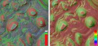
QUOTE (RoverDriver @ Aug 1 2012, 05:54 PM) it is then. I just followed the color scheme we typically use on other products.The blue-green-red scheme comes out chunkier & not as pretty IMO but I suppose it has utility for those of you involved in actually getting the rover around. I.e., if the slope is greater than 25° then it really doesn't matter whether it's 60° or 26°, it's a no-go. I made a comparison image on a small detail:
Doug mentioned that the amount of total area of the rover traps is a minuscule fraction of the total landing ellipse. I take that to say that the probability of a mission failure due to that cause is an order of magnitude less than failure due to other causes, so even if it were eliminated through fancy hazard avoidance methods, the overall chance of failure wouldn't be affected very much. -------------------- |
|
|
|
|
|
|
Aug 2 2012, 12:25 PM
Post
#310
|
|
|
Member Group: Admin Posts: 976 Joined: 29-September 06 From: Pasadena, CA - USA Member No.: 1200 |
QUOTE (jmknapp @ Aug 2 2012, 04:24 AM) The blue-green-red scheme comes out chunkier & not as pretty IMO but I suppose it has utility for those of you involved in actually getting the rover around. I.e., if the slope is greater than 25° then it really doesn't matter whether it's 60° or 26°, it's a no-go. I made a comparison image on a small detail: That is quite close to what I have! Yes it is not pretty but it will give you and UMSF a back-seat-driver pocket map to follow us along the way. QUOTE Doug mentioned that the amount of total area of the rover traps is a minuscule fraction of the total landing ellipse. I take that to say that the probability of a mission failure due to that cause is an order of magnitude less than failure due to other causes, so even if it were eliminated through fancy hazard avoidance methods, the overall chance of failure wouldn't be affected very much. That is correct. Keep in mind that the size of the ellipse, although much smaller than MER, is still quite large compared to the possible rover traps. In all it turned out a fraction of one percent. Paolo -------------------- Disclaimer: all opinions, ideas and information included here are my own,and should not be intended to represent opinion or policy of my employer.
|
|
|
|
|
Aug 2 2012, 01:00 PM
Post
#311
|
|||
|
Senior Member Group: Members Posts: 1465 Joined: 9-February 04 From: Columbus OH USA Member No.: 13 |
UNNECESSARY QUOTING REMOVED _ ADMIN
That is quite close to what I have! Yes it is not pretty but it will give you and UMSF a back-seat-driver pocket map to follow us along the way.[/quote] That's a point, for the full Total Recall experience. As for pretty, I guess neither can compete with Van Gogh:
Attached thumbnail(s)
-------------------- |
||
|
|
|
||
|
Aug 3 2012, 08:01 AM
Post
#312
|
|
|
Junior Member Group: Members Posts: 53 Joined: 15-July 09 Member No.: 4867 |
QUOTE (jmknapp @ Aug 2 2012, 01:24 PM) if it were eliminated through fancy hazard avoidance methods, the overall chance of failure wouldn't be affected very much. You are right, but this should not be the case for future missions landing in much riskier areas.
|
|
|
|
|
Aug 3 2012, 11:59 AM
Post
#313
|
|
|
Senior Member Group: Members Posts: 1465 Joined: 9-February 04 From: Columbus OH USA Member No.: 13 |
Per Paolo's description of the coloring scheme used in JPL's slope maps, I redid mine:
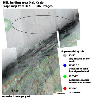 Click on the above image to go a blog post with a link to the full-res image. I cropped the image to keep it under 30,000 pixels in width and height, so it should be viewable by more programs. -------------------- |
|
|
|
|
Aug 3 2012, 12:47 PM
Post
#314
|
|
|
Member Group: Admin Posts: 976 Joined: 29-September 06 From: Pasadena, CA - USA Member No.: 1200 |
That is great, Joe! One of the things I will be doing once we are on the ground, is to validate the slope map by comparing it to the IMU measurements as we drive around. I'm not sure what telemetry will be released to the public this time, but if the vehicle attitude is reported in the image header you can do the same evaluation and adjust the map accordingly.
Paolo -------------------- Disclaimer: all opinions, ideas and information included here are my own,and should not be intended to represent opinion or policy of my employer.
|
|
|
|
|
Aug 3 2012, 02:49 PM
Post
#315
|
|
|
Senior Member Group: Moderator Posts: 4279 Joined: 19-April 05 From: .br at .es Member No.: 253 |
QUOTE (jmknapp @ Aug 3 2012, 01:59 PM) ... I cropped the image to keep it under 30,000 pixels in width and height, so it should be viewable by more programs. I'm wondering how would it look on Google Earth. Some time ago I worked with MapTiler to create some background map tiles for Endeavour Crater (Opportunity site) and I think it may be able to handle this picture. Probably, the only real problem will be to correctly register the image (i.e. find the right lat / long coordinates for the corners). Stay tuned. |
|
|
|
|

|
Lo-Fi Version | Time is now: 27th April 2024 - 12:10 AM |
|
RULES AND GUIDELINES Please read the Forum Rules and Guidelines before posting. IMAGE COPYRIGHT |
OPINIONS AND MODERATION Opinions expressed on UnmannedSpaceflight.com are those of the individual posters and do not necessarily reflect the opinions of UnmannedSpaceflight.com or The Planetary Society. The all-volunteer UnmannedSpaceflight.com moderation team is wholly independent of The Planetary Society. The Planetary Society has no influence over decisions made by the UnmannedSpaceflight.com moderators. |
SUPPORT THE FORUM Unmannedspaceflight.com is funded by the Planetary Society. Please consider supporting our work and many other projects by donating to the Society or becoming a member. |
|