MSL Descent and Landing - Remastering MARDI imagery |

  |
MSL Descent and Landing - Remastering MARDI imagery |
 Oct 10 2013, 06:03 PM Oct 10 2013, 06:03 PM
Post
#16
|
|
|
Senior Member  Group: Members Posts: 2511 Joined: 13-September 05 Member No.: 497 |
I can't parse this. We never sent the data in raw form, but lossless compression means you decompress them and then they're in raw form. This is as close to raw as will ever be released.
The RDR DXXX product is essentially raw. -------------------- Disclaimer: This post is based on public information only. Any opinions are my own.
|
 |
 
|
|
Oct 26 2013, 12:16 PM
Post
#17
|
||
 Newbie Group: Members Posts: 8 Joined: 3-October 13 Member No.: 7010 |
Upon further inspection on what is available in PDS, I've hit a major snag. The raw data is a small subset of what was previously recorded in comparison with the whole JPG sequence found here > http://mars.nasa.gov/msl/multimedia/raw/?s...mp;camera=MARDI
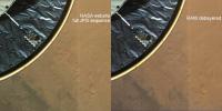
This means from a total of 1283 frames recorded there are about 650 - 750 frames relevant for the EDL and on the PDS website, the latest release is only 388 frames long. A quick look indicates that this release is showing every 3rd frame of what was captured. This means I am forced to work with the full JPG sequence in order to compute the whole camera motion. About the raw non de-bayered images I tried debayering blindly, without respecting the tables in the documentation. I have found that there are two schemes for interpolating the green channel but there is more work to be done here. One conclusion is that the compression is applied, probably o board the craft for memory reasons. 4GB of DRAM if I remember correctly. The point is that even the non de-bayered images are exhibiting signs of spatial compression thus reducing the color fidelity by introducing visible color macro-blocks. Quick comparison in the attachment.
Attached thumbnail(s)
|
|
|
|
|
|
|
Oct 26 2013, 12:19 PM
Post
#18
|
||
|
Newbie Group: Members Posts: 8 Joined: 3-October 13 Member No.: 7010 |
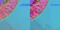
This is a HSV colorspace version to further show the chrominance macro-blocking.
Attached thumbnail(s)
|
|
|
|
|
|
|
Oct 26 2013, 03:36 PM
Post
#19
|
|
|
Senior Member Group: Members Posts: 2511 Joined: 13-September 05 Member No.: 497 |
QUOTE (AdrianC @ Oct 26 2013, 05:16 AM)  ...from a total of 1283 frames recorded there are about 650 - 750 frames relevant for the EDL and on the PDS website, the latest release is only 388 frames long. Are you sure? A quick look at http://pds-imaging.jpl.nasa.gov/data/msl/M...EX/RDR_CMDX.TAB shows 1280 EDL frames (all as "MrdiRecoveredProducts") though these are inconveniently scattered across releases 1-3 because of their transmission times (32 on 1, 864 on 2, and 384 on 3). QUOTE One conclusion is that the compression is applied, probably o board the craft for memory reasons. Per the documentation, the raw data are the digitized samples coming out of the camera and then passed through a 12-to-8-bit square-root table with no additional lossy compression. I'm not certain what you are concerned about in your images, but we've found that the two green pixels in the Bayer pattern have slightly different responses and this has to be accounted for for best color reconstruction. Bayer reconstruction is a very involved topic. -------------------- Disclaimer: This post is based on public information only. Any opinions are my own.
|
|
|
|
|
Oct 26 2013, 05:09 PM
Post
#20
|
|
|
Newbie Group: Members Posts: 8 Joined: 3-October 13 Member No.: 7010 |
QUOTE Are you sure? A quick look at http://pds-imaging.jpl.nasa.gov/data/msl/M...EX/RDR_CMDX.TAB shows 1280 EDL frames (all as "MrdiRecoveredProducts") though these are inconveniently scattered across releases 1-3 because of their transmission times (32 on 1, 864 on 2, and 384 on 3). This is good news. My only source was MSL Curiosity Analyst's Notebook http://an.rsl.wustl.edu/msl/mslbrowser/br2.aspx?tab=solsumm The search returned only 388 MARDI products. I was under the assumption that this was the whole release. I greatly appreciate the help.  QUOTE Per the documentation, the raw data are the digitized samples coming out of the camera and then passed through a 12-to-8-bit square-root table with no additional lossy compression. I'm not certain what you are concerned about in your images, but we've found that the two green pixels in the Bayer pattern have slightly different responses and this has to be accounted for for best color reconstruction. Bayer reconstruction is a very involved topic. My first concern was that I was forced to use the public JPG images. Not that great for feature detection. My second concern (not being able to correctly parse the raw files and forced to use the DRCL .IMG versions) I was stuck with the moire pattern generated by the different response in the green pixels. Again, thanks for the valuable information. I will now try to implement the decompanding tables. |
|
|
|
|
Oct 26 2013, 05:31 PM
Post
#21
|
||
|
Newbie Group: Members Posts: 8 Joined: 3-October 13 Member No.: 7010 |
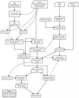
I'm posting a workflow diagram to better illustrate the process I'm trying to follow.
Please note I made this from memory on my phone, please excuse any errors. The diagram is based on the assumption that the main image source is compressed.
Attached thumbnail(s)
|
|
|
|
|
|
|
Oct 26 2013, 06:53 PM
Post
#22
|
|
|
Senior Member Group: Members Posts: 2346 Joined: 7-December 12 Member No.: 6780 |
Is the varying color of the terrain due to surface specularity and changing camera position implicite in your flow-chart?
I'd think, that specularity needs to be subtracted away to get phong light conditions and surface specularity separated for an appropriate texture / vertex definition and rendering. Or do you intend to switch textures during the sequence (working purely with phong), as an alternative? |
|
|
|
|
Oct 26 2013, 08:08 PM
Post
#23
|
|
|
Founder Group: Chairman Posts: 14432 Joined: 8-February 04 Member No.: 1 |
QUOTE (AdrianC @ Oct 26 2013, 10:31 AM) I'm posting a workflow diagram to better illustrate the process I'm trying to follow. At that point - why not just render an animation derived from the MARDI imagery. You're so far from the original data you might as well just make a composite HiRISE / MARDI image mosaic, drape it over a HiRISE DTM and rotoscope it to match the MARDI frames. |
|
|
|
|
Oct 26 2013, 10:27 PM
Post
#24
|
|
|
Senior Member Group: Members Posts: 2511 Joined: 13-September 05 Member No.: 497 |
QUOTE (djellison @ Oct 26 2013, 01:08 PM) why not just render an animation derived from the MARDI imagery... It's unclear from the processing flow, but it's possible that that's essentially what he's proposing. That said, estimating the position and pose of each MARDI frame would be a useful contribution all by itself. -------------------- Disclaimer: This post is based on public information only. Any opinions are my own.
|
|
|
|
|
Oct 30 2013, 07:54 PM
Post
#25
|
|
|
Newbie Group: Members Posts: 8 Joined: 3-October 13 Member No.: 7010 |
QUOTE s the varying color of the terrain due to surface specularity and changing camera position implicite in your flow-chart? I'd think, that specularity needs to be subtracted away to get phong light conditions and surface specularity separated for an appropriate texture / vertex definition and rendering. Or do you intend to switch textures during the sequence (working purely with phong), as an alternative? @Gerald Specularity will be substracted from each image. This will definitely keep the result close to the original. I was thinking of complementing the effect with a simple shading model, but in the images we get lots of phenomenons like: specularity, atmospheric diffraction, CCD amplifier glow (vertical glowing strips mostly visible when the shield detaches) etc. There will be texture switching but performed only on the frames of substracted specularity which will be added back on the final composite. On the other hand the CCD amplifier glow will be an added effect, because the shield will be an actual animated 3D object with textures derived from the original, but with CG shadows. QUOTE It's unclear from the processing flow, but it's possible that that's essentially what he's proposing. That said, estimating the position and pose of each MARDI frame would be a useful contribution all by itself. @djellison and @mcaplinger That is correct. Summing the whole process to a few words is basically MARDI imagery draped over HiRise elevation data. The key difference I am trying to make is to keep the whole process as scientifically accurate as possible in order to derive some interesting data like: instant altitude, instant velocity, orientation, amount of dust blown before touchdown, etc. Everything depends on how all the data sets come together. As a digital VFX artist we usually work with artistic impressions of reality, and mostly because of time constrains, just plain old empirical approaches of just about everything. It may not sound like what "making of" promotional materials describe about movie VFX, but it's just how things are done in this industry. After a whole decade I find this disappointing and inefficient process, with too much decision weight on untrained people like some directors and directors of photography. I'm not naming people but imagine that some DOP's have immensely limited knowledge about optics and basic light behavior and sometimes physics in general. Please excuse this rant, it's strictly my opinion, but this is one of the main reasons I started this project. It's because I want it to have quantifiable results, not end up as an artistic impression or some "simulation". |
|
|
|
|

|
Lo-Fi Version | Time is now: 26th April 2024 - 08:54 AM |
|
RULES AND GUIDELINES Please read the Forum Rules and Guidelines before posting. IMAGE COPYRIGHT |
OPINIONS AND MODERATION Opinions expressed on UnmannedSpaceflight.com are those of the individual posters and do not necessarily reflect the opinions of UnmannedSpaceflight.com or The Planetary Society. The all-volunteer UnmannedSpaceflight.com moderation team is wholly independent of The Planetary Society. The Planetary Society has no influence over decisions made by the UnmannedSpaceflight.com moderators. |
SUPPORT THE FORUM Unmannedspaceflight.com is funded by the Planetary Society. Please consider supporting our work and many other projects by donating to the Society or becoming a member. |
|