Viking '75 Science Test Lander, Detail photographs of the Science Test Lander from Viking '75 |

  |
Viking '75 Science Test Lander, Detail photographs of the Science Test Lander from Viking '75 |
 May 16 2012, 03:59 AM May 16 2012, 03:59 AM
Post
#1
|
|
 Member  Group: Members Posts: 101 Joined: 3-May 12 From: Massachusetts, USA Member No.: 6392 |
Recently I spent an enjoyable afternoon photographing the Viking '75 Mars Lander
which is on display at the Virginia Air and Space Center in Hampton VA. Based on many details, I am sure this is the so-called Science Test Lander (STL) which was installed in the NASA/JPL "sandbox" during the missions. I have uploaded 277 detail photos (totaling nearly 2GB) to a Picasa Web album. (As far as I know, the best/only way to download them all is to install and execute Google's free Picasa application for Windows PCs. Note a quirk with the Picasa Web magnifier tool: on large images such as these, the full resolution usually is not loaded right away when you activate the magnifier. If you wait ten seconds or so, usually the full 4K-pixel version will become available via the navigator pop-up in the corner. Sometimes it never does, however.) The STL in its current museum display configuration has two very interesting attributes. First, the insulation blankets and cloth covers which normally surround the fuel tanks, associated plumbing, and roll-control thrusters has been removed. I happily captured a fair number of photos of the exposed (and complex!) fuel-system plumbing, valves, wiring, and thrusters. Second, the lander's bottom cover plate has been cut open in the 30-inch square area normally covered by the Terminal Descent Landing Radar (TDLR) box. The TDLR is not installed; instead it is mocked-up on two side with tall white flanges. I would like to see an accurate TDLR someday (the Smithsonian's Proof Test Capsule is also missing a TDLR), so it's a bit of a shame not to find one here. However, the trade-off is wonderful -- the large opening in the bottom allows a peek at the lander's interior! It is not really possible to see visually inside, due to geometry of the museum display, but a carefully-positioned camera can get some views. :-) The STL body is essentially empty, but a few interesting details are present. The dacron-covered insulation blankets lining the interior sidebeam walls are there, restrained with authentic vertical nylon ties. The Equipment Plate is installed, which is a large hexagonal aluminum plate spanning the interior about five inches down from the lander's top cover plate. (The computer, batteries, science instruments, radios, etc. were bolted to and hung from the bottom of the Equipment Plate.) The plate is partially painted black (for thermal control) in areas which were not to be covered by mounted components, and this is visible. The thin coolant-loop tubing which snakes around the underside of the Equipment Plate is there. The three cylindrical struts from which the TDLR was to be hung are there. The Thermal Switches to which the Radioisotope Thermoelectric Generators were mounted are there, and I managed to capture a peek at the flexible copper "Contactor" of one of them. The STL has somewhat simplified external wiring, and the externally-mounted electronics units on sides 1 and 3 are simple wood mock-ups. This includes the Inertial Reference Unit, the two Radar Altimeter Electronics units, and the Valve Drive Amplifier. The three Terminal Descent Engines are also mostly wood mock-ups, however TDE #2 (on the "front") has an authentic top plate and gold thermal shield. I was able to take a number of detail measurements, which will eventually be incorporated into plans I've barely begun to create. All in all, I was very happy to have made the trip to see this lander. -- Tom |
 |
 
|
|
May 18 2012, 10:15 AM
Post
#2
|
|
 Member Group: Members Posts: 796 Joined: 27-February 08 From: Heart of Europe Member No.: 4057 |
This is really nice and huge Viking Lander gallery. Thanks!
-------------------- |
|
|
|
|
May 18 2012, 11:38 AM
Post
#3
|
|
 Member Group: Members Posts: 495 Joined: 12-February 12 Member No.: 6336 |
Thank you for sharing those images.
'They don't build them like that anymore' J/k.  And perhaps not joke there, many of those welded and bolted on parts do indeed look heavy. Especially compared to how such a lander would be built today, or yesteryear also for that matter like Phoenix. But yes it is one amazing piece of engineering. |
|
|
|
|
May 18 2012, 06:57 PM
Post
#4
|
|
 Administrator Group: Admin Posts: 5172 Joined: 4-August 05 From: Pasadena, CA, USA, Earth Member No.: 454 |
Is this the same model that was the star of the "Mars in 3D" video?
-------------------- My website - My Patreon - @elakdawalla on Twitter - Please support unmannedspaceflight.com by donating here.
|
|
|
|
|
May 18 2012, 08:46 PM
Post
#5
|
|
|
Member Group: Members Posts: 101 Joined: 3-May 12 From: Massachusetts, USA Member No.: 6392 |
QUOTE (elakdawalla @ May 18 2012, 01:57 PM)  Is this the same model that was the star of the "Mars in 3D" video? It seems very likely that the lander in that film was the STL, but I've only seen a low-res version and did not study the frames in detail. Thus assuming that the lander in the Virginia Air and Space Center pictured in my album is indeed the STL (more on that in another reply to come), yes they are the same. -- Tom |
|
|
|
|
May 18 2012, 11:51 PM
Post
#6
|
|
|
Member Group: Members Posts: 101 Joined: 3-May 12 From: Massachusetts, USA Member No.: 6392 |
I would like to verify the origin of the lander which is on display at the Virginia Air and Space Center (VASC). I believe it is the Science Test Lander (STL) for reasons listed below; however, perhaps it has some other origin. I hope the community can come to a conclusion. I have written to the curator of the VASC but have not received a response in a couple of weeks.
Firstly, here are three certain photos of the STL: one linked near the bottom of this page by Don Davis (a contributor to this forum), one from NASA, and a second similar one. I have been using these photos for identification. Landers created by Martin Marietta A basic question is what landers were created by Martin Marietta in the first place? There were of course three "Flight Capsule" landers: FC1 and FC2 which are on Mars, and FC3 (backup) which is now in the Museum of Flight near Seattle. I have a large photo album for FC3 here. What about non-Flight landers? There is a list on page 258 of NASA SP-4212 "On Mars" which states: "The major Viking simulators included: Lander (structural) dynamic-test model (LDTM). A flight-style structure with partial flight-style or equivalent propulsion lines and tanks. Mass (weight) simulators were used for nonstructural hardware. The LDTM was used for structural vibration, acoustic noise, separation tests, and pyrotechnic shock evaluation. Lander (structural) static-test model (LSTM). A flight-style structure used for qualification of the primary structure under steady-state and low-frequency loads. Orbiter thermal effects simulator (OTES). A simulator used to study the orbiter's thermal and shadowing effects during the lander-development thermal environmental tests. Proof-test capsule (PTC). A complete Viking lander capsule assembly assembled from flight-style hardware, used for system-level qualification. [This is at the Smithsonian NASM.] Structural landing test model (SLTM). A 3/8, geometrically scaled model of the lander, dropped at various velocities and attitudes to determine landing stability boundaries. The 3/8 scale was chosen because the Martian gravity was 3/8 that of Earth's. Thermal-effects test model (TETM). A full-scale model incorporating developmental thermal control systems and flight cabling test harness. Flight equipment thermal effects were simulated by special equipment. The TETM was used to verify the system developed for controlling the temperature of the lander." [Here is a photo of the TETM which I scanned from a copy of NASA SP-336 I own.] One major question in my mind is: which of the above is the STL? I do not think the JPL-STL is the PTC. The PTC is on display at the Smithsonian NASM, and I've taken a few hundred photos of the PTC. Many details do not match. However, I do suspect that the lander pictured in the famous photograph with Carl Sagan in Death Valley is the PTC, not the STL. For example the loose-fitting fabric cover on fuel tank #1, the detail wrinkling of the main fuel-line insulation (especially just above the aeroshell shear fitting near the left end of sidebeam #2), and the gray colors of the large electrical connectors for the aeroshell (along the bottom edge of short side #2 and sidebeam #2) suggests this conclusion. Clues that the VASC Lander is the JPL-STL Here are some observations which suggest to me that the lander at the VASC is the Science Test Lander. Some of these are pretty obscure; bear with me! For what it's worth the PTC at the Smithsonian does not match these various details. * Mock-up Terminal Descent Landing Radar box below the lander. The VASC lander has two deep white sheet-metal flanges which represent two sides of the 30-inch square TDLR box. The STL has a white TDLR box which looks similar from the "front." * There are various survey target "bulls-eye" stickers on the lander, such as near the Load Limiter mounts along the lower corners of sidebeam #2 and near the tops of the primary support fittings for landing legs #2 and #3. * Details of how insulation is wrapped around the main fuel line which runs across the lower face of sidebeam #2. See the down-pointing triangle bulge near the aeroshell shear fitting near the left end, and the general thickening near the right end. The fuel-line insulation on the PTC and the STL differ considerably, both in the above details and in that the STL insulation has much tighter wrinkles overall. * The orange electrical cable extending vertically amid the fuel, pressurant, and coolant lines which go up in front of RTG #1's windcover (which were designed to pass through the Base Cover and Bioshield cap). I'll grant that the JPL-STL has two such orange cables, whereas the VASC lander has only one, but I haven't seen even one on other landers. * The heavily-bolted body panel on the right half of short side #3. Just to the right of the primary support fitting for leg #3 is a panel with four columns of fasteners. This is lacking on the PTC (and Flight lander bodies). * The hand-inked black serial number lettering on the sides of the leg bipod struts. They each have the numeral 1, 2, or 3 written near the footpad end, and some have "S/N 000000x" written near the Load Limiter end. (Curiously on the VASC lander, the bipod struts for legs #1 and #3 have been swapped!) * The thick black electrical connector for one of the three aeroshell connections -- the one along the bottom edge of short side #2 -- has a tilted or sloped damaged top. These are black mock-up connectors, different than the functional gray ones on the PTC. * The stitching (or similar) along the top rim of the protective box for the Meteorology Sensor Assembly when stowed. The PTC has a smooth plastic-looking box. (The Flight landers have yet different boxes, with pressed stiffener ribs.) * The folding of insulation on the large six-element electrical connection box on the left side of sidebeam #2 below the surface sampler, and the particular arrangement of only three cables. * The markings on the fixed post of camera #1, in particular the blue NASA property sticker. (I'm not sure how many authentic Itek cameras have such a sticker, but it's lacking on the Flight lander cameras, the PTC cameras, and the development unit camera at the NASM.) * The fact that Radar Altimeter Electronics #2 (mounted on top of the lander near the High Gain Antenna) is a plain gold-colored mock-up, in contrast to essentially all the other top-mounted components which look very authentic. Don Davis's STL photo is consistent with the VASC lander in this manner. All of the above strongly suggests to me that the VASC lander is the Science Test Lander from JPL. Also, the other landers on display here and there (e.g., NASM, KSC, Kansas Cosmosphere, and California Science Center) differ from the STL in numerous ways. Thus the STL is not at those institutions. Mis-matches between VASC Lander and the STL There are some mis-matches between the VASC and JPL-STL landers, however. * The American flag marking on RTG #2's windcover is in a different position. * Camera #2's fixed post is different (though both the VASC and JPL-STL landers have an unusual dark lower half). * The white fabric contamination fairings which cover the upper primary struts for the landing legs have different "hose clamps" at top and bottom. * On the side of the Meteorology Boom Assembly's hinge, the VASC lander has a dark-colored blank rectangle in the position where the TRW manufacturer data plate would be. The MBA on the JPL-STL has no data plate of any kind. * The orange electrical cable which connects to the Meteorology Boom near its mount is covered with thick caulk-like material on the VASC lander, which obscures the shape of the underlying cable connector components. On the JPL-STL it is possible to see the smooth cylindrical orange connector parts. Perhaps these discrepancies could be explained by swaps of components during the latter stages of the STL's life, but they are puzzling. One definite swap can be found in Terminal Descent Engine #2, near the surface sampler. The overhead image by Don Davis shows a clear mock-up engine (with whitish nozzles, gold-painted thermal side shield and smooth gold top), whereas the NASA side-view photos show metallic nozzles and an authentic-looking very reflective gold-plated thermal shield. Conclusion So where did the VASC's lander come from? I think it's the STL. More generally where did the STL come from? Is it a conversion of the LDTM, LSTM, or TETM? I don't know. |
|
|
|
|
May 21 2012, 02:59 AM
Post
#7
|
|
|
Member Group: Members Posts: 101 Joined: 3-May 12 From: Massachusetts, USA Member No.: 6392 |
To aid those interested in studying the details which I mentioned in the prior reply, I have assembled a few photo montages which make the comparisons fairly clear (you may wish to use Picasa-Web's magnifying class feature to see the full-resolution images):
* Survey target "bulls-eye" markings * Fuel line insulation * Body panel and aeroshell electrical connectors * Hand-drawn lettering on bipod struts The images I used of the Science Test Lander as installed at JPL during the mission are here and here. The photo of Carl Sagan in Death Valley is from here. The images of the landers at the Virginia Air and Space Center, and at the Smithsonian National Air and Space Museum (the Proof Test Capsule), were taken by me over the past few months. |
|
|
|
|
Jan 12 2013, 03:35 AM
Post
#8
|
|||
|
Member Group: Members Posts: 101 Joined: 3-May 12 From: Massachusetts, USA Member No.: 6392 |
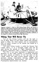
I recently discovered some new (to me) information about the origin of the Viking lander known as the "Science Test Lander" (STL). There is an article titled Viking That Will Never Fly in the August 11 1975 issue of the Langley Researcher newsletter. Accompanying the article is a photograph (reproduced below) of the STL with the caption:
QUOTE Engineers Leonard V. Clark of VPO (Viking Project Office) and Vernon P. Gillespie of SED (System Engineering Division) discuss the status of the Viking Science Test Lander being fabricated by personnel of SED and FID (Flight Instrumentation Divisions). This full-scale working model of the Viking Lander will be shipped to JPL (Jet Propulsion Laboratory) in Pasadena, California, in late August for utilization during Viking Flight Operations.
The article essentially confirms in my mind that the circa-1975 STL is a distinct unit from the Proof Test Capsule (now in the Smithsonian National Air and Space Museum) which was assembled earlier by Martin Marietta in Denver and used extensively in numerous test programs during lander development. The full text of the article reads as follows: QUOTE Viking That Will Never Fly Not all the Viking Landers will see the light or life on Mars. While its two sisters mated with Orbiters, speed to Mars, the third capsule will sit complacently here on Earth, content to be viewed and tested as a working model. The third Viking Lander is called the Science Test Lander (STL). It is a full-scale model that will be used during the period of Flight Operations at Jet Propulsion Laboratory (JPL) in Pasadena, California. The STL is an exact duplicate in appearance and geometry of the Flight Landers. A particular emphasis has been placed on fidelity of the top deck of the Lander where the Mars surface sample inlets to the principle science instruments (biology, GCMS (Gas Chromatograph/Mass Spectrometer) and XRFS (X-ray Fluorescence Spectrometer) are located. An important feature of the Lander model is its operational subsystems, namely, a pair of facsimile cameras and a surface sampler. The cameras will be operated to scan 360 degrees to take panoramic pictures of the area around the Lander. They can be used in a special "line scanning" mode to detect motions. Its color filters can perform chemical minerology investigations on the surface near the Lander. The surface sampler can be commanded to reach out its retractable ten foot arm, scoop up the Mars surface samples and deposit the grains into the mini-laboratories that will perform the experiments. The model has been assembled at Langley using an assortment of surplus hardware from the many test programs that preceded the building of the flight Lander components. The STL will be shipped to JPL in late August. It will be installed by Langley staff in the Atrium adjacent to Von Karman Auditorium. The Atrium, enclosed by floor to ceiling glass viewing windows, was reconstructed and powered to house the working model in a suitable surrounding. The facility will be operational by October. The Surface Sampler Team of the Viking Science Group is responsible for the operational phase. By testing and studying this working capsule, the crew will be able to understand, command and control the other two Landers for their performance and data return. The facility will initially be used to provide camera and surface sampler data for the Lander Simulation System, and to support Flight Team Test and Training exercises. Later, the STL will be used extensively by the Imaging and Surface Sampler Teams to develop an instrument performance data base, to develop command sequences for nominal and off-nominal situations, and to develop and verify flight commands. Sometimes called the "Kiwi" or "Gooni Bird" by the joking staff, who nonetheless are proud to be its guardian, the STL will provide an interesting close-up display during its working hours to the fascinated viewers. Edited to add some more information: I was re-reading a set of Viking Mission Status Bulletins that I acquired a while ago, and came across a definitive statement in the cover story of No. 36, about Lander 1's early surface sampler locking-pin troubles. The story includes the following statement clearly indicating the independent status of the STL and PTC: QUOTE The situation was quickly evaluated, and tests were made to duplicate and determine the nature of the problem using the science test Lander at JPL and the proof test Lander at Martin Marietta in Denver.
|
||
|
|
|
||
|

|
Lo-Fi Version | Time is now: 25th April 2024 - 08:08 PM |
|
RULES AND GUIDELINES Please read the Forum Rules and Guidelines before posting. IMAGE COPYRIGHT |
OPINIONS AND MODERATION Opinions expressed on UnmannedSpaceflight.com are those of the individual posters and do not necessarily reflect the opinions of UnmannedSpaceflight.com or The Planetary Society. The all-volunteer UnmannedSpaceflight.com moderation team is wholly independent of The Planetary Society. The Planetary Society has no influence over decisions made by the UnmannedSpaceflight.com moderators. |
SUPPORT THE FORUM Unmannedspaceflight.com is funded by the Planetary Society. Please consider supporting our work and many other projects by donating to the Society or becoming a member. |
|