Juno at Jupiter, mission events as they unfold |

  |
Juno at Jupiter, mission events as they unfold |
 Aug 1 2016, 03:30 PM Aug 1 2016, 03:30 PM
Post
#61
|
|
|
Senior Member  Group: Members Posts: 2346 Joined: 7-December 12 Member No.: 6780 |
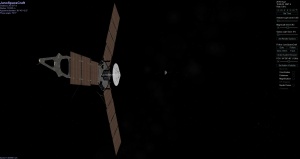
A refined Jupiter Approach AVI.
I've removed images 588, 624, 672, 1006, 1185, and 1186, since they caused flickering. The rendered version of image 1006 is invalid by a cause which is to be investigated. The other five images don't show Jupiter. You'll barely perceive a color channel misalignment in the AVI. [Obsolete, see edit: Edit: Ok, I found the simple cause for the misalignment in some of the still to be published version of the stills: The conversion from BMP to PNG hasn't been completed for the latest parameter adjustment, when I assessed the quality of the PNG stills. The AVI used the BMPs, and should be of acceptable quality. Stills are in preparation for post. |
 |
 
|
|
Aug 2 2016, 03:45 AM
Post
#62
|
|
|
Senior Member Group: Members Posts: 2346 Joined: 7-December 12 Member No.: 6780 |
Added still images of refined version.
Besides images 1006, and the five black images, rgb channel registering should be better than one raw pixel, now. Next, I'm intending to quantify the remaining subtle mismatch, and to find a subspace of best parameter settings consistent with the Jupiter Approach images, in order to accelerate the search for the correct parameter settings, once the expected raw perijove images will become available. The latter search initially needs to consider more degrees of freedom, which will be reduced this way. |
|
|
|
|
Aug 2 2016, 04:13 AM
Post
#63
|
|
|
Member Group: Members Posts: 890 Joined: 18-November 08 Member No.: 4489 |
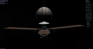
Juno is on it's way back to Jupiter
|
|
|
|
|
Aug 2 2016, 09:02 AM
Post
#64
|
|
 Member Group: Members Posts: 238 Joined: 15-January 13 Member No.: 6842 |
If Juno will be passing over the night side of Jupiter during its close approaches, is there a chance it could photograph lightning and aurora on Jupiter? It would also be cool to see close-up photos of the terminator line, aka the sunsets and sunrises in Jupiter's clouds.

-------------------- Curiosity rover panoramas: http://www.facebook.com/CuriosityRoverPanoramas
My Photosynth panoramas: http://photosynth.net/userprofilepage.aspx...;content=Synths |
|
|
|
|
Aug 2 2016, 11:23 AM
Post
#65
|
|
|
Senior Member Group: Members Posts: 2346 Joined: 7-December 12 Member No.: 6780 |
Juno's trajectory will likely be suitable to probe Jupiter's aurora from the inside. If a sequence of subsequent JunoCam images will be taken, it might be possible to apply tomography to obtain information about the 3d structure of the aurora in different wavelength bands. Other Juno instruments (Juno-UVS) at least will try to do so. Being able to add according data from the visible spectrum would be great.
It might also be possible to retrieve additional radiation (flux) data from JunoCam images. If there are lightnings at the proper instant, JunoCam should be able to see them, but it may require some disambiguation from energetic particle impacts. The PJ1 images near August 27 will give us a first idea of what's possible. |
|
|
|
|
Aug 2 2016, 08:28 PM
Post
#66
|
|||||
 IMG to PNG GOD Group: Moderator Posts: 2250 Joined: 19-February 04 From: Near fire and ice Member No.: 38 |
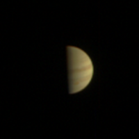
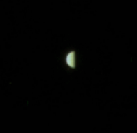
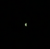
I have been experimenting with the color in the Juno images by multiplying the green and blue values with correction coefficients >1. Here is the last image (JNCE_2016181_00C1588_V01.png) that shows the GRS without any color correction:
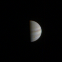
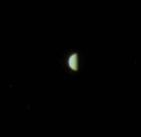
North is up and the image has been enlarged by a factor of 4. It is obviously too yellowish. Here the color balance has been adjusted to make the average color of the bright zones approximately white. This is common practice when processing Earth-based images of Jupiter. This is much more realistic than the version above.
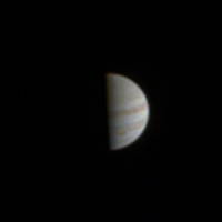
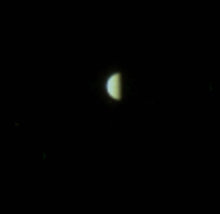
And here is a sharpened version. This image shows hints of various familiar features.
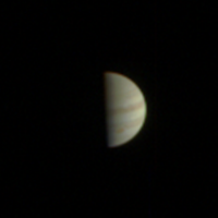
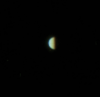
And here is yet another version which has been processed to make the global color match Jupiter's global spectrum. This is only approximate, both because the viewing geometry is very differenet from the viewing geometry of Earth based instruments and because Jupiter's global color varies slightly with time.
This may be slightly more realistic than the version processed to make the zones whitish. I also get acceptable results if I correct the color balance using the parameters that work well for correcting the EFB images (like the Jupiter images they are also too yellowish if the color is not corrected). Of course this raises some questions: (1) Are there any 'official' color correction/calibration coefficients that are used to get correct color? I have been using ~1.1 for green and 1.4 to 1.7 for blue. (2) If these coeffcients exist, are they constant or do they vary with things like exposure, gain etc.? |
||||
|
|
|
||||
|
Aug 2 2016, 08:41 PM
Post
#67
|
|
 Senior Member Group: Members Posts: 1630 Joined: 5-March 05 From: Boulder, CO Member No.: 184 |
Interesting to see the version that matches the global color spectrum. In this case it looks like the bright zones are yellowish instead of white? What type of data is there for Jupiter's spectrum?
-------------------- Steve [ my home page and planetary maps page ]
|
|
|
|
|
Aug 2 2016, 09:08 PM
Post
#68
|
|
|
Senior Member Group: Members Posts: 2346 Joined: 7-December 12 Member No.: 6780 |
QUOTE (Bjorn Jonsson @ Aug 2 2016, 10:28 PM)  I have been experimenting with the color in the Juno images by multiplying the green and blue values with correction coefficients >1. Here is the last image ... Of course this raises some questions: (1) Are there any 'official' color correction/calibration coefficients that are used to get correct color? I have been using ~1.1 for green and 1.4 to 1.7 for blue. (2) If these coeffcients exist, are they constant or do they vary with things like exposure, gain etc.? I've been hesitating to use factors >1 in order to avoid saturation, but this might be unnecessarily conservative. There exists a radiometrically corrected version as linearized RDRs of the EFBs. That's probably what comes closest to "official". By calibrating Earth's moon to grey vs. Earth's clouds to grey/white I got different results for the factors. I doubt, that there exists a perfect color calibration, since the spectral characteristics of the JunoCam color filters and the human color receptors differ significantly. And it's not quite clear, whether extinction by Earth's atmosphere should be included in the calibration; the latter seems to vary pretty much particularly for the blue color band. As I've mentioned in some other post, there doesn't seem to exist a common convention of how to color-calibrate Jupiter images. The approach to set the mean color to grey would make best use of the color space in some way, but then one can't expect, that the color looks "natural" at the same time. |
|
|
|
|
Aug 2 2016, 10:44 PM
Post
#69
|
|
|
Senior Member Group: Members Posts: 1630 Joined: 5-March 05 From: Boulder, CO Member No.: 184 |
I think the bright Earth clouds would be a better white reference, and matching the color of the sun better that itself is a pretty good approximation of white as seen from space. The moon apparently has a slight color - though I forget which direction it is.
-------------------- Steve [ my home page and planetary maps page ]
|
|
|
|
|
Aug 3 2016, 12:54 AM
Post
#70
|
|
|
Senior Member Group: Members Posts: 2346 Joined: 7-December 12 Member No.: 6780 |
Ah, yes, this could resolve the discrepancy. I've seen material from Earth's moon from less than a meter distance, and it looked perfectly grey. But it likely wasn't directly from the surface. If Moon's surface reddens from space weathering, then it should look reddish, consistent with the appearence of Moon in EFB01, after I've been following your advice to use Earth's clouds as white calibration targets. (One of the (large!) resulting processed EFB12 files here.) However, the color of the clouds aren't quite uniform, so this a compromise.
Since then I've applied the weights (0.74, 0.88, 1.0) for square-root encoded (r,g,b ). Stretching to red=1.0, this would correspond to (1.0, 1.19, 1.35) for square-root encoded (r,g,b ), or to about (1.0, 1.41, 1.83) for linearized (r,g,b ). The CCD should behave close to linear with exposure time, according to subsection 4.1 of the JunoCam paper: QUOTE Linearity and full well were measured using integrating sphere images taken with a series of exposure times. This shows excellent linearity (r = 0.99) until the full well is reached at about 1872 DN (30,500 electrons), illustrated in Fig. 18.
|
|
|
|
|
Aug 5 2016, 11:47 AM
Post
#71
|
|||||||||
|
Senior Member Group: Members Posts: 2346 Joined: 7-December 12 Member No.: 6780 |
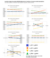
Quantitative measurements of the structure and velocity of Jupiter's cloud top may require a very accurate calibration of JunoCam's geometry.
However, when going well below one raw pixel alignment accuracy, it's hard to measure inaccuracies visually. Here seven animated examples, one for each of seven considered camera parameters, with five frames for each of the animated gifs. You may try to find out in which of the gifs you can perceive a change of color at the limbs, before looking at the graphics below. Varying the assumption of JunoCam frames per Juno rotation:
Varying the x/z ratio of the pinhole part of the model:
Varying the x-position of the optical axis:
Varying the y-position of the optical axis:
Varying the Brownian radial distortion coefficient K1:
Varying the Brownian radial distortion coefficient K2:
Varying the assumption of the JunoCam CCD being rotated around its optical axis:
The subtle changes of the RGB misalignment can be quantfied more accurately by comparing the positions of the centroids for each color band in the processed images:
The misalignment unit in the graphics and data is 30 arc seconds, or about 1/4 raw pixel. Here the values as csv file:  JNCE_2016164_00C196_V01_proc013.BMP_RGBGradCSV.txt ( 10.09K )
Number of downloads: 224
JNCE_2016164_00C196_V01_proc013.BMP_RGBGradCSV.txt ( 10.09K )
Number of downloads: 224The graphics suggests locally linear dependence of the misalignments on the considered parameters. The misalignment can hence be approximated well by a system of linear equations, eventually written as y=Ax+b, with x,y,b vectors, and A a matrix. Since the number of parameters is 7, but there are only 4 linearly independent measurements, the space of solutions with (close to) perfect alignment is likely to be 3-dimensional for each image. The set of solution spaces for a sequence of images can then undergo statistical analysis. The graphics also suggests, that the x-alignment of the blue channel (yellow lines) can reasonably be obtained only by adjusting the y-position of the optical axis and/or adjusting the rotation of the camera around the optical axis, unless additional parameters are added to the model. |
||||||||
|
|
|
||||||||
|
Aug 8 2016, 11:18 PM
Post
#72
|
||
|
Senior Member Group: Members Posts: 2346 Joined: 7-December 12 Member No.: 6780 |
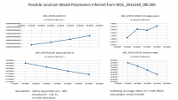
Based on images JNCE_2016164_00C196 to JNCE_2016164_00C220, and assuming 80.943 JunoCam frames per Juno rotation,
Brownian K1=-0.00000003839251, K2=2.6E-015, I found an x/z pinhole scale factor of 1477.939165 +/- 0.275290, an x-position of the optical axis of 835.665952 +/- 3.204528, a y-position of the optical axis of 601.001077 +/- 1.892324, the CCD rotated around the z-axis by 0.002747 +/- 0.000225 radians, (0.157 degrees), with 1-sigma error bars over the considered data set, or 5-sigma error bars of the means by a sample size of 25, and normal distribution presumed. The parameters have been optimized for each image individually. The above parameters and errors are mean and standard deviation over the individual images (not the standard deviation of the mean). The maximum misalignment of the red and green centroid along either x or y relative to the green centroid was -0.032618/120 degree (about 0.01 raw pixels). The applied model is a spinning pinhole model distorted by a purely radial Brownian model with coefficients K1 and K2, slightly rotated around the optical axis. Most of the values look credible, but I doubt, that the x-position of the optical axis can be made consistent with EFB images and SPICE trajectory data. Therefore I think, that some assumption is wrong. For completeness, I'm intending to modify the three constant parameters, i.e. number of frames per rotation, K1, and K2, as an approach to register the color channels. But I'm skeptical (based on preliminary data), that the misalignments will turn out to be sufficiently sensitive with respect to these parameters to be able to allow for a good value for the x-position of the optical axis, and to stay consistent with EFB images and with laboratory data. Hence I expect considering a small chromatic aberration as the most promising approach to resolve the misalignments in an overall consistent way. Parameters for each of the considered images:
JNCE_C196_C220_RGBAlignCSV.txt ( 7.24K )
Number of downloads: 218An aligned example images (C197) :
|
|
|
|
|
|
|
Aug 9 2016, 05:04 PM
Post
#73
|
||
|
Senior Member Group: Members Posts: 2346 Joined: 7-December 12 Member No.: 6780 |
Image JNCE_2016164_00C200 is sensitive to the number of JunoCam frames per rotation.
So, I've chosen this image to explore the 3-dimensional subspace of RGB-aligned solutions within the 7-dimensional space of the considered family of camera models, which assume zero chromatic aberration. This graphics assumes the optical axis at y = 600, and a Brownian K2 = 2.6E-15. It varies the x-position of the optical axis:
These assumptions imply a CCD rotated around z by about 0.00283 radians. This is the according csv file:
JNCE_2016164_00C200_V01_proc014b_1_00x.BMP_RGBGradCSV.txt ( 1.25K )
Number of downloads: 215I tried K2 = 0; the effect has been tiny:
JNCE_2016164_00C200_V01_proc014c_1_00x.BMP_RGBGradCSV.txt ( 1.25K )
Number of downloads: 217K2 affects mainly the area near the left and right margin of the images. Since in the images Jupiter is closer to the center, the subspace of main interest for the Jupiter Approch sequence is the 2-dimensional projection which neglects K2. Assuming y = 620 reduced the z-rotation of the CCD:
JNCE_2016164_00C200_V01_proc014d_1_00x.BMP_RGBGradCSV.txt ( 1.25K )
Number of downloads: 230This led me to set the z-rotation of the CCD to zero. The result is a y-position of the optical axis near 624.5 (without adjusting for TDI) :
JNCE_2016164_00C200_V01_proc014e_1_00x.BMP_RGBGradCSV.txt ( 1.25K )
Number of downloads: 231For the lab value of K1 = 3.839251E-8, K2 = 0, and zero CCD rotation, I got an optical axis position near (835.0; 624.6) (with (0; 0) at the lower left, and again without adjusting for the 1.5 pixels y-displacement for TDI 4) :
JNCE_2016164_00C200_V01_proc014f_1_00x.BMP_RGBGradCSV.txt ( 404bytes )
Number of downloads: 235 |
|
|
|
|
|
|
Aug 9 2016, 05:29 PM
Post
#74
|
|
|
Senior Member Group: Members Posts: 2511 Joined: 13-September 05 Member No.: 497 |
To be honest, I'm not really sure what you're trying to do here. IMHO, the small-disc Jupiter images are not great for assessing fine-scale distortions because they don't cover a large area of the field and there's not a straightforward error metric that you can minimize, like residuals in star images would have. Unfortunately we haven't taken RGB star images because of TDI limitations, but maybe we need to look into what we could do along those lines.
Be warned that spin axis knowledge may need to be refined post JOI and PRM burns because of s/c balance changes. There's also some evidence of nutation effects that I have yet to track down. Mods: I think that this whole discussion should be moved to the "Juno PDS data" subforum, and that subforum be renamed to better reflect a detailed technical discussion of Juno instrument specifics. -------------------- Disclaimer: This post is based on public information only. Any opinions are my own.
|
|
|
|
|
Aug 9 2016, 05:43 PM
Post
#75
|
|
 Administrator Group: Admin Posts: 5172 Joined: 4-August 05 From: Pasadena, CA, USA, Earth Member No.: 454 |
QUOTE (mcaplinger @ Jul 29 2016, 09:00 AM) One minor nit: two of the last three images (1586 and 1588) were taken with TDI 1. It may be worth pointing out that south is up in all of these. Our final processed images are rotated 180 degrees. These issues are, belatedly, fixed. I'll work on forum organization when I have time. -------------------- My website - My Patreon - @elakdawalla on Twitter - Please support unmannedspaceflight.com by donating here.
|
|
|
|
|

|
Lo-Fi Version | Time is now: 29th April 2024 - 11:22 AM |
|
RULES AND GUIDELINES Please read the Forum Rules and Guidelines before posting. IMAGE COPYRIGHT |
OPINIONS AND MODERATION Opinions expressed on UnmannedSpaceflight.com are those of the individual posters and do not necessarily reflect the opinions of UnmannedSpaceflight.com or The Planetary Society. The all-volunteer UnmannedSpaceflight.com moderation team is wholly independent of The Planetary Society. The Planetary Society has no influence over decisions made by the UnmannedSpaceflight.com moderators. |
SUPPORT THE FORUM Unmannedspaceflight.com is funded by the Planetary Society. Please consider supporting our work and many other projects by donating to the Society or becoming a member. |
|