Printable Version of Topic
Click here to view this topic in its original format
Unmanned Spaceflight.com _ Past and Future _ Viking '75 Mars Lander Construction
Posted by: Tom Dahl May 17 2012, 12:38 AM
Greetings all! I am searching for detailed construction and design information about the NASA Viking '75 Mars project hardware, particularly for the lander, aeroshell, base cover, and bioshield. Can anyone recommend good sources? I am especially looking for engineering drawings and under-construction photographs.
To set the stage, here is an https://picasaweb.google.com/113792041573871319555/VikingLanderDiagrams?authuser=0&feat=directlink&noredirect=1 drawings and photos which I've collected so far.
I have already read the "usual" books, such as NASA RP-1027 "Viking '75 Spacecraft Design and Test", the press kits, the scientific papers produced about the mission, a number of industry papers covering various instruments and subsystems, the major Martin Marietta books, etc. I am hoping to find additional sources. Any ideas?
Also, does anyone know if there are aeroshell, base cover, or bioshield components lurking in a museum or in storage somewhere?
FYI, I have visited three of the best landers still on Earth: The Proof Test Capsule in the Smithsonian NASM, the Flight Capsule 3 (backup) in the Museum of Flight near Seattle, and the Science Test Lander in the Virginia Air and Space Center. I've taken nearly 1,000 photos of the three of them (most of which are publicly available in other Picasa Web albums of mine). I've taken a few measurements, but I would dearly love to find more authoritative drawings of more hardware (interior, exterior, everything). I have begun submitting some Freedom of Information Act requests to NASA/JPL which has started to bear some trivial but kind of fun fruit.
---
Update as of March 2017: During the past few years I have been fortunate enough to collect a significant amount of information on the Viking lander hardware. My thanks to a number of organizations for providing me access to their resources:
- http://www.thevikingpreservationproject.org
- http://www.museumofflight.org
- https://www.nasa.gov/langley
- https://californiasciencecenter.org
- http://www.vasc.org
- https://airandspace.si.edu
https://goo.gl/photos/hedHCChRTyAbsN7W9
https://goo.gl/photos/bp6qyitviWuS55VCA
https://goo.gl/photos/DPPq6cci1dNQJRVP9
https://goo.gl/photos/nwr4Mt2CAaHYJraw9
https://goo.gl/photos/kk3cojepePDNo3yg6
https://goo.gl/photos/fPBQcWmbmo8gbwzt8
https://goo.gl/photos/zEF5GqU7D8WZWSVGA
https://goo.gl/photos/7HoHmLFPzzL3eYee8
https://goo.gl/photos/FDcpciijf1HSjj2G7
https://goo.gl/photos/sczxRikkwJ2DB83j8
https://goo.gl/photos/pPY6yjAum8BBYxjR7
https://goo.gl/photos/JyKWiSegW9rVDAcL8
https://goo.gl/photos/14Ldse5HR3EWJjYa7
https://goo.gl/photos/WGbCanF4ugRVXRV17
https://goo.gl/photos/K6gmGctCWjX7kRMaA
https://goo.gl/photos/dGEy1SLphDRKEgCu8
https://goo.gl/photos/CGCyfMukJZde3MxQ8
https://goo.gl/photos/mwqoNUkLXdVn6X5t9
https://goo.gl/photos/CjNUtwXwfFCgrBC57
The main focus of my efforts during the past few years has been to create an accurate and high-fidelity digital 3D model of the Viking lander. I've chosen to use the https://www.sketchup.com software to build the model because a near-full-featured free version is available, allowing other people to use my model. The 3D model itself, as a work-in-progress, is https://www.dropbox.com/s/ulbw4ukmvbfyc6g/Viking%20Lander.skp?dl=0. I update that model file periodically as major elements get added. I've created an album containing numerous https://goo.gl/photos/bcdFG1M2YMwQqyfq9 of digital model components, and I have a https://www.youtube.com/channel/UCL223KT3dfyv_hGzdnsrw5g/videos?shelf_id=0&view=0&sort=dd with some videos about the modeling project. I have also uploaded the https://3dwarehouse.sketchup.com/model/u9531a20a-cbee-4b19-af25-69ebc01ce0f9/Viking-75-Mars-Lander-Core-Body and the https://3dwarehouse.sketchup.com/model/d5d47be8-62cd-4b50-beba-79398231108c/Viking-75-Mars-Lander-Surface-Sampler-Collector-Head to the SketchUp 3D Warehouse so that other people can easily access those components (the 3D Warehouse can be accessed from within SketchUp, or via web browser). The file on DropBox lister earlier contains those components and others.
-- Tom
Posted by: tasp May 17 2012, 12:32 PM
Can't remember where I read this, but at least one piece of a spare aeroshell assembly wound up in someones backyard.
Seems like I saw a pic somewhere. Maybe Sky and Telescope a LONG time ago.
Posted by: Tom Dahl Jun 21 2012, 02:40 AM
I have begun creating a 3D model of the Viking lander, attempting to be fairly detailed and as accurate as I can manage (based on the references I have, including some 900 photographs I've taken of three authentic landers). I recently completed my first pass at the lander's sidebeam #1, which forms one third of the lander's hexagonal body. Here is https://picasaweb.google.com/lh/photo/YK2b9Cmb3gXecs_x0B8p29MTjNZETYmyPJy0liipFm0?feat=directlink of the backup lander body in the Museum of Flight near Seattle.
The model linked above represents the solid machined aluminum beam without any of the brackets, fittings, and flanges which are bolted or screwed to the sidebeam. The attachment points for all those brackets etc. are represented as carefully-located bolt holes. As I understand it, each sidebeam consists of a lander-body long side and half of the adjacent two short sides. The three sidebeams are apparently connected to each other via the vertical landing leg https://picasaweb.google.com/lh/photo/MvsF3IwLRP9vdREuxNN59tMTjNZETYmyPJy0liipFm0?feat=directlink, which are bolted across and under the joints between adjacent sidebeams. The top and bottom cover plates also help to hold the body together; fastener locations for those plates are included in the model.
Proportions of the model are based on dimensions I have taken from some authentic landers, various published references, and a lot of photo interpretation and cross-check. I have been careful to ensure that the various points of contact between the lander and its aeroshell are reconciled (three large bolts, one under each leg primary support fitting; six shear points, two under each sidebeam; and three guiderail roller assemblies).
If anyone has corrections or questions, I would be pleased to address them!
Posted by: Tom Dahl Jul 9 2012, 02:06 AM
I am looking for a good-quality version of an image published in NASA Ref. Pub. 1027, "Viking '75 Spacecraft Design and Test Summary: Volume 1 - Lander Design" issued by the Langley Research Center in 1980. Figure 20 "Lander Body" (on page 25) is what I hope to find.
The http://ntrs.nasa.gov/archive/nasa/casi.ntrs.nasa.gov/19810001592_1981001592.pdf (10MB) on the NASA Technical Reports Server has an almost illegible image of Figure 20. I have examined two original printed copies of RP-1027 from nearly libraries; in both cases the original halftone printing of Figure 20 is fairly poor. https://picasaweb.google.com/lh/photo/TVAMbGu4rV4b5xp3axAj69MTjNZETYmyPJy0liipFm0?feat=directlink which I scanned at 400 DPI from one of the copies.
Does anyone know if a photographic print or high-resolution scan of that image is available in some archive somewhere? I recently sent a message to the "Contact Langley" web site asking about this image, in case that turns it up.
Edited to add: as a prior reply mentions, I am creating a 3D digital model of the lander. My intention is to make that model freely available, both as a 3D SketchUp mesh and as 2D blueprints. The purpose of the blueprint form is to aid my ultimate goal of scratch-building an actual model, probably 1/8th scale. My https://picasaweb.google.com/113792041573871319555/VikingLanderDiagrams?authuser=0&feat=directlink&noredirect=1 (including "Figure 20" linked above, which shows the lander's internal Equipment Plate) are already shared, in case they help folks also interested in the Viking project.
Posted by: Tom Dahl Aug 11 2012, 04:10 AM
I've now completed the first-pass 3D model of the lander's three sidebeams. https://picasaweb.google.com/lh/photo/PBYQvqSvQH7-dQeVOj77ZtMTjNZETYmyPJy0liipFm0?feat=directlink, and one render by itself (sidebeam 3 is in the lower right, #1 on the left, and #2 in the upper right, with meteorology boom mounting bracket attached):
This is only a small fraction of the job, but it's nice to see the shell of the lander in the round.
-- Tom
Posted by: Tom Dahl Aug 29 2012, 02:27 AM
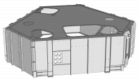
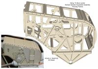
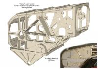
For those following at home  I have added the Viking lander's top cover plate to my 3D model. It was a challenge to reconcile the externally-visible features with Martin Marietta's drawing of the interior Equipment Plate (instrument locations, support posts, etc.). I've tried to minimize the discrepancies. Here is a line drawing of the overall body:
|
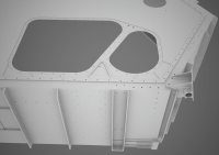
And here is a close-up of the right upper corner of sidebeam 2. Prominent are the mount for the meteorology boom and magnet cleaning brush (on the right corner), and large openings in the top cover for camera 1 (on the right), the biology and gas chromatograph mass spectrometer inlet processors (on the left), and thermal switch contactor for Radioisotope Thermoelectric Generator 1 (partly visible at top):
|
The current state of the 3D model is https://dl.dropbox.com/u/91575394/Viking%20Lander.skp (6.8MB; hopefully it's downloadable).
I had a very enjoyable phone conversation today with Prof. Jim Tillman of the University of Washington, who along with his daughter were principal agents in saving and restoring the Flight Capsule 3 (backup) lander body. I'm hoping to return to visit the FC3 in the Museum of Flight near Seattle in a few weeks. I'm glad I could share a bit of my enthusiasm for the Viking program with Prof. Tillman and thank him for saving an important historic object.
Posted by: djellison Aug 29 2012, 03:41 AM
There is a model - I'm not sure of its fidelity - at the California Science Center. If there are details there that could be useful, let me know and I'll head over with a camera.
Doug
Posted by: nprev Aug 29 2012, 09:38 AM
IIRC, they've got the actual ground engineering test lander in the lobby of the National Air & Space Museum in DC. I wonder if the curators there have complied a dataset of public-domain information on same; might be worth an e-mail.
Posted by: Tom Dahl Aug 29 2012, 12:46 PM
Hi Doug -- regarding the California Science Center's lander, thank you very much for the offer! I suspect that unit is a replica created by Penwal Prototypes, rather than an authentic Martin Marietta unit. I base this largely on the photo shown on the http://www.penwalprototypes.com/portfolio/signature-projects.html (look for the Viking Lander thumbnail), compared to on-line photos I've found of the CSC's lander. Details such as Camera 1's clear housing; the mock-up BIO and GCMS inlet processors; the silver foil bands on some leg's white cloth contamination fairing skins; the dark bands wrapping the meteorology boom cabling; the fuel tank and roll-control thrusters, and fuel-line routing and joints. I wrote to Penwal a few months ago asking about their replica and whatever references they may have had, but never received a response.
Overall I don't think it is authentic enough for my purposes, except I am very curious about the exposed camera 1. Did Penwal manage to acquire a surplus original ITEK facsimile camera unit? It seems out of character with the rest of the lander; too much detail. So I would very much enjoy seeing some photographs of that camera's innards (both the upper rotating opto-mechanical part, and the lower fixed electronics part) from various angles. If possible!
Hi nprev -- that's the Proof Test Capsule in the National Air and Space Museum. I've actually visited it three times in the last year, and accumulated about https://picasaweb.google.com/113792041573871319555/VikingMarsLander?authuser=0&feat=directlink&noredirect=1 of that fantastic unit. I have not yet attempted to contact the NASM archive division, which I really should do! Thanks for the nudge.
Posted by: Tom Dahl Nov 12 2012, 06:11 PM
In September had the opportunity to spend a couple of days at the Museum of Flight near Seattle WA, and study the Viking lander Flight Capsule 3 (flight-backup) on display there. I took over 500 detail photographs of the lander. I recently completed processing (e.g., brighten shadows, diminish background distractions, add captions) and have uploaded them to a Google https://picasaweb.google.com/113792041573871319555/VikingLanderFC3?authuser=0&feat=directlink&noredirect=1 if anyone else is interested. They join about 180 photos of the FC3 I had taken a year ago.
The images are about 12MPixels in size. If you use Picasa web's magnifying-glass tool to see the full version, it usually takes five seconds or so before the complete image is available. Before then the little zoom-navigation widget only goes to about half size; the bar will re-scale to access the full detail when ready.
I also had a chance to meet Chris Vancil and Eckart Schmidt, both of whom worked to restore the FC3 for display (Eckart worked during the mission at Rocket Research Company on the terminal descent engines), and also Ron Hobbs of the museum staff. It's a great facility with an amazing collection.
Posted by: Tom Dahl Jun 7 2013, 03:57 PM
A few months ago I was delighted to acquire a vintage set of blueprints of the "Viking Lander Body Structure Assembly" by Martin Marietta. With the permission of the UMSF administrators I am making scans of them available to all, hoping they provide useful information or at least enjoyable viewing. Here is a https://picasaweb.google.com/113792041573871319555/VikingLanderBodyBlueprints?authuser=0&feat=directlink&noredirect=1.
Overview
I suspect this set of blueprints was intended to guide assembly of the core body and its myriad brackets and fittings, rather than to support the fabrication of the various piece parts. There are extensive dimensions listed on the plans (which is what I find so valuable!), but not enough to fully define the parts. The print set consists of 35 sheets. Sheet 1 is composed of over 100 individual pages, consisting of notes, parts lists, and Design Change Notices. Sheets 2 through 35 are the actual shop drawings (one large page per sheet). In the above album I have shown the drawing sheets first, then the various notes pages. What follows in this message are some of my interpretations and explanations of the contents of this historic blueprint set.
Five Lander Body Variants
Martin Marietta's part number for the core lander body is 837J3100000. The plans show five (5) distinct variants of the body, denoted with tags -009, -010, -019, -020, and -029. All five have unique features (generally quite small). Variants 9 and 29 are fairly close to each other; 10, 19, and 20 have a lot in common. I would love to learn what variants correspond to which manufactured lander body units. There is a table on Sheet 1 https://picasaweb.google.com/lh/photo/Uj4Qw8Oq_yXNZZCajy1uZ-g0AB190KvrXvgQeGCzRsQ?feat=directlink&noredirect=1 which seems to list the five body variants with cryptic nomenclature:
ASSY/PART NO. --- NEXT ASSEMBLY --- TT
837J3100000-009 --- 837K0100000 --- PC (?Proof Test Capsule, PTC?)
837J3100000-010 --- 837J1000200 --- TM (?Thermal Effects Test Model, TETM?)
837J3100000-019 --- 837J2000200 --- SD (?Lander Structural Dynamic-Test Model, LDTM?)
837J3100000-020 --- 837J3000200 --- SS (?Lander Structural Static-Test Model, LSTM?)
837J3100000-029 --- 837K0100000 --- <blank>
I don't know the meaning of the "TT" column, but I'll guess that it represents the purpose or role of the lander units (perhaps Test Type). If so, I wonder if the table's two-letter designations represent the test units who's names I've added to the table in parentheses. For what it's worth, the Flight Capsule 3 (backup) lander body in Seattle's Museum of Flight has stenciling from Martin Marietta on https://picasaweb.google.com/lh/photo/3T9Ylrc_YI5rcuymf_O_odMTjNZETYmyPJy0liipFm0?feat=directlink&noredirect=1 which includes the notation "P/X 837K0100000-009" (as well as "S/N 0000003"). This suggests that the FC3 body is of variant type -009; perhaps the two Flight bodies FC1 and FC2 are also this type?
According to the set's revision history information, the initial release of the prints was on 27 June 1972. The revisions incorporated into this set occurred during the interval from 7 March 1973 to 15 January 1975 -- just seven months prior to launch of Viking 1. The last few revisions are mostly re-labeling of part-numbers or changes to fasteners. (Assembly of the Flight landers had been largely completed by late 1974.)
The lander body components are assigned Martin Marietta part numbers generally of the form 837J310xxxx-yyy, where xxxx identifies the component and yyy identifies a specific variant. For example 837J3100053-001 is the Surface Sampler's main mount (which happens to only come in one variant). The drawings often do not identify a specific variant in overview contexts, but all components have a formal variant tag. Sheet 1's parts-list pages include a group for each of the five lander variants (e.g., pages 9.001 to 9.021 contain the parts list for variant 9; pages 19.001 to 19.017 list parts for variant 19). I have collated all parts-lists pages into a https://docs.google.com/spreadsheet/pub?key=0Apy4CXbgbQHxdHlDdkdpWmxLeWFGY19seVFGY29TNkE&output=html showing which component variant belongs to which body variant(s). The spreadsheet also enumerates the drawing sheet(s) on which the given component is notably visible.
Scan Process
My paper copies of the drawing sheets are printed on C-size (17 x 22 inch) sheets, reduced from the master E-size (34 x 44 inch) sheets. The reduction is by a bit over 50%; Martin Marietta's reduction-copy process was a bit casual, yielding some skewed orientations accommodated by wide margins. I suspect this print set came from two different master original printings, because some sheet images are slightly larger with different borders than others. I have rectified the scans to be squared to the image area and of uniform size. I scanned the paper sheets at 600 DPI, which yields an image of about 120 million pixels (nearly 13K by 10K pixels). Google's PicasaWeb service currently allows a maximum image size of 50M pixels, therefore the album contains 300 DPI versions. Each sheet's image caption includes a link to a full-resolution version on DropBox.
A few of the drawing sheets are fairly clear prints, but most have extensive background mottling introduced in Martin Marietta's copy/print process. I have begun digitally cleaning the scans. In order to avoid loss of faint and obscured detail this is largely a manual masking job, which is very tedious. To date I have completed masking the first three drawing sheets (numbers 2, 3, 4). I hope to occasionally replace others with cleaned versions. A few of the sheets have annotations applied by a prior owner of the set. I will be removing such annotations during masking.
Lander Body Size
All linear dimensions are in inches and are usually specified to thousandths. These blueprints confirmed my earlier suspicion that the hexagonal body's long and short side lengths of 43 and 22 inches as stated in some NASA documents are incorrect. The long side length is approximately 43.359 inches; the published figure probably resulted from a simple rounding. However, the short side actual length is approximately 24.566 inches, which is about 10% larger than the published value. The height of the core body (excluding top and bottom covers and some integrally-machined protrusions) is exactly 18.000 inches, which agrees with the published value.
By the way the odd values for the side lengths are not direct design parameters. They are derived from the actual design parameters which are the distances from the body geometric center to the perpendicular midpoints of the sides. The design distance from the body center to the midpoint of a long side is specified as exactly 26.700 inches. From body center to midpoint of a short side is specified as exactly 32.125 inches. Application of some mathematics yields the side length values listed above. (I was pleased to discover that length estimates I had made earlier, based on known https://picasaweb.google.com/lh/photo/K7o_gOK9kRyoZ7-xXWwoSNMTjNZETYmyPJy0liipFm0?feat=directlink&noredirect=1, a scale https://picasaweb.google.com/lh/photo/3zZLv00h0MP0qgCjQ1HnGNMTjNZETYmyPJy0liipFm0?feat=directlink&noredirect=1, and knowledge of the nine-point interface between Aeroshell and lander, were only off by a few hundredths of an inch.)
The core lander hexagonal body consists of three (3) sidebeams, each machined from a single piece of aluminum. The three sidebeams are broadly similar but differ in numerous details (flanges, holes, stiffeners, etc.). The sidebeams are spliced or butted together with the vertical joints on the centerlines of the three landing legs. Therefore each sidebeam represents one complete long side and the halves of two adjacent short sides (appearing as angled short "wings" seen from above). Here is a https://picasaweb.google.com/lh/photo/YK2b9Cmb3gXecs_x0B8p29MTjNZETYmyPJy0liipFm0?feat=directlink&noredirect=1 I've created of sidebeam 1.
Blueprint Notations
Each of the drawing sheets has a border dividing the sheet into an 8 by 8 grid of 64 zones. Zone coordinates range from 1 to 8 (bottom to top) and A to H (right to left). One portion of a drawing will frequently refer to another view or section on the same or a different sheet. Such zone references are denoted by a square containing number / letter coordinates, with a small sheet-number outside the upper right corner.
Large circles with multi-line text generally represent part numbers (e.g., 837J3101042-009) or fastener types (e.g., ST25D40-5-3).
Small circles containing a dash and three digits denote a simple flat shim part (of which the lander contains dozens). Sometimes the circle is omitted. The three-digit number is the variant tag for the shim's part number, all of which belong to the overall lander part number 837J3100000. For example, a notation of "-075" refers to shim 837J3100000-075. The parts-list pages show the shim's nominal sizes, with width and height larger than final to allow for trimming tolerances. The drawing sheets generally show the final shim sizes (which I've listed in the above spreadsheet when known).
Horizontal triangles containing a number are flags which reference one of the notes listed on pages https://picasaweb.google.com/lh/photo/ltp63TfVi1ODE0sdmRXFIug0AB190KvrXvgQeGCzRsQ?feat=directlink&noredirect=1 to 2.003 of sheet 1. Such notes detail process operations, assembly instructions, etc.
Small rectangles define construction reference planes, or specify tolerances in relation to a reference plane or point. In the following example the lower rectangle defines the associated feature (not seen in this fragment) to be Plane E. The upper rectangle specifies that this plane must be parallel ("||") to Plane A (defined elsewhere) within 0.020 inches.
A few features on the lander required a particular degree of machined surface finish. These are denoted with a stylized kind of letter J with an adjacent number (representing the roughness average value in microinches).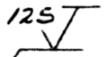
Anachronism
Most of https://picasaweb.google.com/lh/photo/ylPWatM5dsBO988gX-EGm-g0AB190KvrXvgQeGCzRsQ?feat=directlink&noredirect=1 is devoted to a prominent component which is not present on the final Flight-type lander bodies. It is an earlier design for the lander's Radar Altimeter Antenna mount (described in the parts list as "Support-LAA" and belonging to body variant 10). https://picasaweb.google.com/lh/photo/RrlCDHW3TOzmfhR5j8GzSNMTjNZETYmyPJy0liipFm0?feat=directlink&noredirect=1 of the Thermal Effects Test Model (TETM) has such a projecting assembly, visible at the right upper corner of the front of the inverted body (which corresponds to the lower left corner of sidebeam 2). This reinforces the idea that body variant -010 was used for the TETM, and that "TM" in the table I listed near the top of this write-up is the Thermal Model.
Posted by: Tom Dahl Aug 17 2013, 06:44 PM
Thanks to the extremely kind assistance and cooperation from the staff at the California Science Center I have been able to take detailed measurements and photographs of the Viking lander on display at the CSC. I owe a huge debt of gratitude to David Gansen, Frank Hernandez, and Ken Phillips of the CSC senior staff for facilitating my recent visit -- thank you gentlemen!
My https://picasaweb.google.com/113792041573871319555/VikingLanderAtTheCSC?authuser=0&feat=directlink&noredirect=1 is now available, with captions. Also available is an https://picasaweb.google.com/113792041573871319555/VikingLanderMeasurements?authuser=0&feat=directlink&noredirect=1 totaling over 300 individual measurements.
I used a variety of tools to capture the measurements, principally a high-quality 6-inch dial caliper and 12-inch outside caliper. Longer or hard-to-reach features were measured with a small tape measure (with ability to directly measure diameters). Angular measurements were made with a digital angle gauge. Profiles were captured with a multi-tooth plastic contour gauge. Broad curves were captured with flexible curve templates. A few part outlines were directly traced on paper.
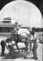
There was discussion earlier in this thread regarding the origin of the lander displayed at the CSC. Last year I had reservations regarding its authenticity based on its numerous mock-up components and the listing of this apparent unit on the Penwal Prototypes http://www.penwalprototypes.com/portfolio/signature-projects.html web site. Over a year ago I had written to Penwal asking about their involvement, but never received a reply. The CSC staff does not have much information regarding the nature of this lander. I have not been able to contact Lockheed Martin, who loaned the unit to the CSC. Then a couple of months ago I found and purchased a vintage 1981 Denver Post https://picasaweb.google.com/lh/photo/iMx7OAfYWzZ-aIjK4GyMVdMTjNZETYmyPJy0liipFm0?feat=directlink&noredirect=1 which appears to show the same lander:
|
The original press caption with that image identifies some Martin Marietta employees who were installing the unit for display at the Denver Pavilion of Science Technology in May 1981. Unusual features matching the CSC's lander include the roll control thrusters (on fuel tank 2) mounted upside down; odd main fuel line routing; and not-quite Flight design of the High Gain Antenna (HGA) mast, drive head, and dish. In addition upon close inspection of the CSC's lander I observed numerous original Martin Marietta part and serial number stencils on lander components. Camera 1 is an authentic Itek lander camera (serial number 0001 according to its data stencil). All of this evidence convinces me now that the lander displayed at the California Science Center is one of the four test units created by Martin Marietta.
It is nevertheless true that various external components are clear mock-ups, including the Meteorology Boom Assembly; camera 2; the Inertial Reference Unit; the Radar Altimeter Electronics and Lander Pyrotechnic Control Assemblies; and the Valve Drive Amplifier (some of which are constructed of wood). Further trivia: leg 3's primary strut differs slightly from the final design; the three Terminal Descent Engines are Rocket Research Company original units, with TDE 1's gold housing featuring a slight variation (square cut-out for the throttle valve).
I had an extremely enjoyable day at the California Science Center, and hope to return in the future (there is much more work to do). Thanks again to David, Frank, and Ken for your hospitality and help!
Posted by: Tom Dahl Jun 23 2014, 02:43 AM
Here is a progress report on my 3D digital model of the Viking lander. I had begun modeling the body in 2012, but started completely over this past winter. During late 2012 and 2013 I had acquired the original blueprints described in a prior reply, and captured a few hundred additional photographs of the landers in the Museum of Flight (Flight Capsule 3 aka the backup body) and the California Science Center (what I suspect is the Thermal Effects Test Model or TETM). These new data motivated me to re-start the model. Here is an overall view of the current effort:
|
Additional renders can be seen in https://picasaweb.google.com/113792041573871319555/VikingLander3DDigitalModel?authuser=0&feat=directlink&noredirect=1. The three core body sidebeams are done, as are the complex top and bottom body dust covers. Mounting brackets for the High Gain Antenna (HGA) deployment mechanism and the Meteorology Boom Assembly (MBA) are complete and give a bit of personality. The most recent additions are the primary support fittings for the three landing legs, and their associated internal body shims and splice-joint plates.
I estimate all features (such as fastener holes) are located to within five or so millimeters of true in the worst cases (requiring complex interpolation); most are within one or two mm or less. Many are exact thanks to the blueprints. The model is being created in the free version of SketchUp; all the component files are available in the following https://www.dropbox.com/sh/irxexra7unnoedy/AABhrrFHzSEFqF_A90ZMArv2a.
Posted by: elakdawalla Jun 23 2014, 03:17 PM
Nice work, and thanks for sharing the SketchUp files so that others may play
Posted by: Tom Dahl Nov 23 2014, 04:17 AM
Update on my project to create a 3D digital model of the Viking lander: I have added more and more core body fittings, brackets, equipment mounts, shims, etc. It's probably not yet recognizable as a Viking lander to most folks, but it's starting to look interesting. I've created a few simple fly-around (and -through) animations of the work-in-progress https://www.dropbox.com/sh/irxexra7unnoedy/AABhrrFHzSEFqF_A90ZMArv2a?dl=0 (in the preceding public directory the file named "Viking Lander" is the composite model with all components in place). They are listed on my brand-new https://www.youtube.com/channel/UCL223KT3dfyv_hGzdnsrw5g/videos. Here are individual links (with video times):
https://www.youtube.com/watch?v=DKn7YSTMuX0
https://www.youtube.com/watch?v=tI_OdL1kf2g
https://www.youtube.com/watch?v=W_eFM7P3tsU
https://www.youtube.com/watch?v=oG_xh6ACid0
Edited to add: if your computer and network access allow it, viewing at full-screen in 720 or 1080 resolution makes for a nice clear image.
Posted by: PaulH51 Nov 23 2014, 05:47 AM

Very impressive, can see the hours that have gone into getting this far. Good luck with the rest of the project.
Posted by: vikingmars Nov 23 2014, 09:22 AM
AWESOME !!! Thanks a lot Tom !

(==> PS : Now, we should add a VL footpad as an emoticon !)
Posted by: droidtoaster Nov 24 2014, 12:35 AM
Amazing Tom, thanks!
When I was at the CSC I was somewhat puzzled by the odd look of their display unit, so your ideas on how it came to be make sense.
For me just the photos are a tremendous resource for vehicle construction; I was quite time limited the day I spent there (with so much to see) and didn't take nearly enough images (a dozen or so) and not from the angles you were allowed. And the comparison notes between the display and designs are fantastic!
Posted by: Tom Dahl Dec 21 2014, 09:17 PM
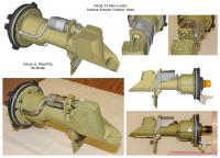
Here is some additional information on Viking lander hardware which I collected in Hampton Virginia USA in November, at NASA's Langley Research Center (home to the Viking Program Office) and at the Virginia Air and Space Center. Thanks to the generous time and assistance of Mary Gainer, LaRC Historic Preservation Officer, I had the rare privilege to examine a Viking surface sampler's Collector Head and Shroud Unit in the LaRC archives. Thanks to the extremely kind cooperation of Allen Hoilman, Curator and Director of Exhibits at the VASC, I was able to spend an entire day (when the VASC was closed to the public) measuring and photographing the Viking lander on display. I believe this unit was the Science Test Lander while at JPL in the 1970s.
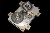
Examining the surface sampler Collector Head Shroud Unit (CHSU) at LaRC was an extreme treat. I have never found high-quality photographs of such a unit, to say nothing of seeing and handling one in person! The LaRC's CHSU is accompanied by a collector head as well (serial number 20). It is a pristine unit, fabulously clean compared to the units mounted on the landers at the VASC and Smithsonian National Air and Space Museum (both of which which saw much testing during the '70s and thus are quite grubby), or the collector head on the lander displayed at the California Science Center (which has a thick coat of cracked and peeling yellow paint). I was able to capture nearly 100 http://tinyurl.com/vikingchsu of the CHSU and collector head. Here is a reduced-resolution sample:
|
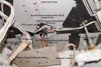
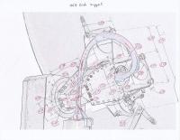
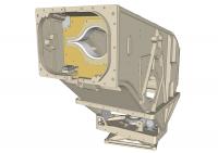
My 11-hour day at the VASC measuring their lander was exhausting but very rewarding. I captured nearly 600 individual http://tinyurl.com/vikingmeasurevasc, and added about 350 detail high-resolution photographs to http://tinyurl.com/vikingvasc of that lander. Most excitingly this includes a number of images capturing the interior (mostly empty) of this lander, which has an open bottom. (I suspect the mounting area for the Terminal Descent Landing Radar (TDLR) was cut from the lander's bottom cover to facilitate disposal of simulant Mars soil samples which were deposited during testing and mission planning into the Processing and Distribution Assembly (PDA) inlets of the Biology and Gas Chromatograph Mass Spectrometer instruments.) Here is an annotated interior image, and a sample of measurements of the Biology PDA:
|

|
Thanks again to Mary Gainer at the LaRC and Allen Hoilman at the VASC for their assistance in allowing me to conduct these examinations.
Posted by: Tom Dahl Jun 17 2015, 12:47 AM
My on-going quest to research the Viking '75 missions recently took me to the Pacific Northwest where I had opportunities to measure and photograph some unusual Viking lander hardware. My thanks to Rachel Tillman and http://jimtillman.net and the http://www.thevikingpreservationproject.org for granting me access to a Meteorology Electronics Assembly (MEA), Tape Recorder (TR), and S-Band High Gain Antenna (HGA), as well as some rare original technical documentation, and also special access to the backup Flight Capsule 3 lander body in the Museum of Flight in Seattle. My grateful thanks also to the http://www.museumofflight.org staff including Senior Curator Dan Hagedorn and Registrar and Accessions Team Leader Christine Runte for facilitating my after-hours access to the FC3. All of your help was critical in making my 3000 mile trip a very enjoyable success.
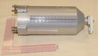
Firstly are about 50 photographs and some measurements of lander http://tinyurl.com/vikingtr serial number 001. The lander tape recorders were unusual in having all-metal recording tape in order to survive the ~240F sterilization temperature to which the complete lander capsules were subjected. This unit lacks its top cover which thus exposes the tape transport and record/playback head mechanisms to view. A marvelous device. For reference https://picasaweb.google.com/lh/photo/1yKMWLCyT5Dc3bcq5pB-WdMTjNZETYmyPJy0liipFm0?feat=directlink&noredirect=1 of one of the lander tape recorders right after its installation within a Flight lander. Here's a reduced-size image of the TR under study:
|
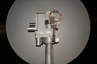
Next up was a session photographing a lander http://tinyurl.com/vikingmsa (MSA). For protection of the MSA's delicate thermocouples this unit is kept within a metal and glass frame which somewhat obscures the view, but keeps the unit pristine. Normally the MSA would be installed at the end of the lander's external deployable Meteorology Boom Assembly (MBA).
I then spent a few hours at the Museum of Flight doing further study of the backup lander body exhibited there. I added some 70 photographs to my album of http://tinyurl.com/vikingfc3, now containing over 700 images. I was especially pleased to capture about 170 total http://tinyurl.com/vikingmeasurefc3 of the Meteorology Boom Assembly and of a landing leg's internal mechanisms.
A few days later I was in Portland OR to study some additional materials. Here are some photographs I was able to capture of technical drawings of the http://tinyurl.com/vikingvmis (VMIS) components. The images suffer from various distortions due to non-flat document pages, a hand-held camera, etc. but they nevertheless record fascinating information such as MBA measurements and internal details of the MBA hinge mechanism.
I captured photographs of a unit I had never seen in person previously, a http://tinyurl.com/vikingmea (MEA) which would be located within the lander body near leg 2. Rachel Tillman and the Viking Preservation Project own serial number 001. Seeing an MEA in person was very nice. For those unfamiliar, here is the MEA:
|
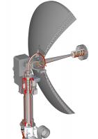
Lastly I spent a couple of hours capturing about 170 measurements and nearly 90 detail photographs of an S-Band http://tinyurl.com/vikinghga (HGA), serial number 21. Because this unit is not mounted on a lander, close-up views from all sides (including the top, normally hard to see) were possible. Here is a taste of the resulting measurements (depicting the dish mount and elevation pivot mechanisms):
|
My thanks again to Rachel Tillman, Jim Tillman, Dan Hagedorn, and Christine Runte for allowing me such a treat to examine authentic Viking artifacts.
Posted by: pospa Jun 17 2015, 12:30 PM
Hi Tom, regarding PDA or better SSPDA (soil sample processing and distribution assembly) you might be willing to contact Steve Jurvetson as he in now the owner of flight qualified Biological instrument unit SN 104 including SSPDA as a newest item of his space artefacts collection. Maybe he could support your effort and let you measure this unit in detail for your 3D modelling purposes.
https://m.flickr.com/#/photos/jurvetson/18595056106/in/set-72157623704246792/
Posted by: Mr Valiant Jun 18 2015, 12:17 AM
Tom,
Your in depth examination of the Viking Lander is exemplary. Viking was my first interplanetary experience.
It was well covered by Australian media at the time, and I cut out from the newspapers every clipping related
to the mission and pasted them in a scrap book. Sadly, that book slowly fell to pieces over the years.
After getting home from primary school, I couldn't wait for Dad to come home from work with the daily
papers, which I would scan, page for page for any scrap of information on Viking.
Just like Apollo, we wonder how so much was achieved with what today is regarded as ancient technology.
It was robust, it was tested inside out, then tested again. It was the best of its day - as we all were.
Many thanks,
Gary Fearon
Posted by: Tom Dahl Aug 31 2015, 02:12 AM
Today's update on my digital 3D http://tinyurl.com/viking3dmodel of the Viking lander (which is freely available at the preceding link): the core lander body is essentially complete, including over 300 unique pieces. To celebrate I created a new https://youtu.be/xvaLlSN4Fiw, about three and a half minutes long, presenting various aspects of the model.
Posted by: monty python Aug 31 2015, 03:46 AM
Wow Tom. Thanks much for the video. It gives me insight into one of my favorite missions and all your hard work.
Posted by: vikingmars Aug 31 2015, 07:57 AM
WOW ! WOW ! WOW ! Incredible Tom... what a NICE work.
If Conway Snyder was still among us, he would have been so happy to see the Viking landers re-born thanks to you !
Posted by: bear10829 Sep 4 2015, 09:27 AM
In case you don't know about this particular treasure trove of high resolution Viking hardware images, have a look at
http://crgis.ndc.nasa.gov/historic/Viking_Archives_Collection.
I was unable to leave that archive before I downloaded every single one of them.
Posted by: Tom Dahl Sep 4 2015, 02:17 PM
Hi bear10829, that is indeed a wonderful archive. In fact I've met Mary Gainer, NASA Langley Research Center's Historic Preservation Officer who is driving the on-going enlargement of that site. With Mary's generous permission I visited Langley in November 2014 to examine and measure a Viking lander surface sampler http://tinyurl.com/vikingchsu that is in the Langley archives. Every few weeks Mary and her team add new images to that archive site.
Posted by: RachelVL3 Nov 1 2015, 04:09 PM
Tom,
Your progress is astounding and it is a pleasure to support your work!
Posted by: Tom Dahl Nov 1 2015, 04:30 PM
Thank you Rachel, I appreciate the compliment and I look forward to our future Viking collaborations. You and the http://www.thevikingpreservationproject.org/ have an incredibly valuable collection.
Posted by: Tom Dahl Jan 16 2016, 02:15 PM
I just completed a https://youtu.be/tKiiQpMdnTM of my work-in-progress digital 3D http://tinyurl.com/viking3dmodel of the Viking lander (which is freely available at the preceding link). This video is nearly six minutes long and shows detailed operation of the lander leg mechanisms, with cut-away sections revealing internal latches, springs, the honeycomb attenuator, pin-puller, etc.
Posted by: Tom Dahl Jun 6 2016, 11:48 PM
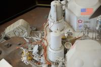
On May 20 I visited the Smithsonian National Air and Space Museum in Washington DC to photograph the Viking lander Proof Test Capsule (PTC), which has recently been undergoing conservation prior to being re-exhibited in the remodeled Boeing Milestones of Flight Hall. Thanks to the very kind assistance of Matthew Shindell, curator in the space history department, and Jessica Bulger of the collections department, I had an hour of special access prior to museum opening. This allowed me to get over and under the lander for detail photography, and include scale references against some components. The result was nearly 900 images I've processed, added descriptions, and uploaded in a new http://tinyurl.com/vikingptc2016.
This was the last time in probably quite a while that 360-degree access will be possible to the Viking PTC due to the new exhibit arrangement that will not allow the "back" (leg 1 area) to be readily seen. For the past few decades the PTC has been exhibited in a very professional glass-walled module, which allowed 360-degree views but mostly through one or two panes of brown-tinted glass. For a short period this spring, including the recent day I was photographing, the lander was removed from that module (which is not being re-used). Thus reflection- and smudge-free images were possible, and I took great advantage of the opportunity - hence the large size of my new album. (During three visits in 2011 and 2012 I acquired about 450 earlier images, some of which suffer from glass artifacts.) Most of the images were taken later on May 20 during normal operating hours, around and between the temporary barriers surrounding the lander. But the early-morning hour with the Smithsonian staff allowed unusual details to be captured, for which I am very grateful! It was a privilege to be granted such access. Thank you Matthew and Jessica.
On a related note my on-going project to create a high-fidelity digital 3D model of the Viking lander continues. I decided to try having a commercial 3D print made of some small parts, for fun. I had to choose something which I had already modeled (of course!), which had a minimum wall thickness large enough to be within the printing capability (which eliminates some parts, even at full scale), and which was not cost-prohibitively large. I chose to print one of the guide roller assemblies that interfaced between the lander and its Base Cover guide rails:
|
The vendor I chose (partly based on materials and print technology availability) is https://i.materialise.com based in Belgium. As can be seen in the image there are three wheels, which spin nicely on their (separately printed) axles. The faceting visible in the curved rollers is how the digital model was designed, for simplicity. The axles have 0.02-in (wide and deep) grooves near their ends for retaining clips, which printed satisfactorily. The wheels and axles were printed in "prime gray" and the body was printed in "high detail resin".
Posted by: Tom Tamlyn Jun 7 2016, 05:53 AM
I had assumed that your interesting project was to create a detailed 3D model of the external shape of the Viking lander. This animation includes some selected internal details. Was that a limited extravagance, or is it your goal ultimately to include all the internal mechanisms as well? Or perhaps you simply intend to pursue as much detail as you can find, whether internal or external.
Did this session satisfy all of your needs for examination of the Proof Test Capsule? Or is there ongoing tension between your interests and the Smithsonian's view of its mission and responsibilities?
Posted by: Tom Dahl Jun 7 2016, 11:42 PM
My main goal is to model essentially all exterior piece-parts of lander hardware (though I'm undecided about a few external components such as the prominent wiring bundles - they would be hard to model and I don't have good data on the routing of the Flight lander wiring, which differs from the PTC and other test-unit wiring in various places). I would like to model the interior but I lack sufficient references to do a high-fidelity job on most items (and doing so would add about two years to the project). I'm doing selected "hidden" parts for which I have good information and which catch my eye, such as the leg mechanisms and the three interior struts that support the large Terminal Descent Landing Radar (TDLR) box below the lander body. I plan to model the Radioisotope Thermoelectric Generators (RTGs) to a good level of detail because they are such iconic devices and I have the info. I'm not sure about internals of the three Terminal Descent Engines (TDEs), I've got almost enough information on them.
In my fantasy I would also model the Aeroshell and its numerous components, and the Base Cover and Mortar Support Truss. But they would entail another couple years' work, so that's very uncertain.
Regarding my recent Viking research at the Smithsonian NASM, it was wonderful and a real privilege to be allowed a one-hour session right up against the lander with a collections specialist! To be clear I am not affiliated with any institutions, the staff did not know me, and I have no formal credentials. Thus being granted that access was an honor for which I am grateful. With that said there was a LOT of additional information I would have loved to acquire. Quite understandably (for the reasons above) I was not permitted to make contact with the lander myself. I did provide references to my earlier visits at NASA Langley, the Virginia Air and Space Center, the California Science Center, the Museum of Flight in Seattle, and the founders of the Viking Mars Missions Education and Preservation Project, who all allowed me to take direct careful measurements of authentic lander hardware. I could have spent ten hours gathering measurements and still not covered everything on my "PTC Bucket List." But I completely understand why that was not permitted.
Posted by: Tom Dahl Aug 7 2016, 01:18 PM
I recently completed a 12-minute https://youtu.be/1vyzoWudom8 that illustrates some of the research methods and modeling approaches I've been taking during creation of the Viking lander digital model.
In July I was delighted to show and discuss the model at the 40th landing anniversary event organized by the http://www.thevikingpreservationproject.org, with a personal invitation by Rachel Tillman. The event was sponsored by Lockheed Martin and held at the Wings over the Rockies Air and Space Museum in Denver CO. The lander was built by Lockheed Martin heritage company Martin Marietta just outside Denver. I met a number of original Viking folks at the event, which was a treat!
Posted by: Tom Dahl Nov 22 2016, 01:11 AM
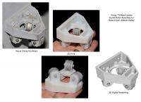
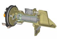
This past weekend I completed a 3D digital model (using SketchUp) of the Viking lander's Surface Sampler Collector Head, a complicated electro-mechanical device. Here is an image comparing the model to an https://goo.gl/photos/pPY6yjAum8BBYxjR7 that I was able to examine at NASA Langley Research Center in 2014:
|
The 3D model contains all major and many minor internal components which allow it to virtually "operate" as the real thing. Here is a cut-away showing the internal sealed DC gear-motor (in gray), the motor-housing/gimbal structure (partly in green, to signify a somewhat approximated design due to lack of references), the solenoid (behind the lid), and the ring magnet arrays in the backhoe:
|
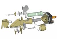
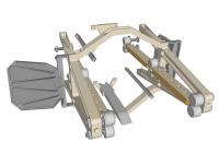
Here is an exploded view of the parts:
|
The model has been uploaded to the https://3dwarehouse.sketchup.com/model.html?id=d5d47be8-62cd-4b50-beba-79398231108c. My thanks to the http://www.thevikingpreservationproject.org for providing some valuable collector head internal design documentation from Martin Marietta.
Posted by: Tom Dahl Dec 24 2016, 04:30 PM
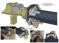
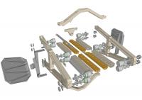
I've completed modeling the hardware that mounts the Surface Sampler Collector Head to the sampler boom or arm. Here are some renderings of the model:
|
|

|
Posted by: rlorenz Dec 25 2016, 03:58 PM
Amazing achievement, Tom. Keep posting about this great project..
Posted by: Tom Dahl Mar 28 2017, 02:53 PM
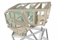
Making progress on the Surface Sampler Acquisition Assembly (SSAA) housing, from which the furlable boom (with collector head mounted at tip) extends and retracts. Here are the eight frames comprising the housing's structure. The numerous skin panels which are bonded or screwed to the frames are not yet modeled.
|
|
Posted by: djellison Mar 28 2017, 03:44 PM
As someone who has dabbled in various 3D platforms for some time - including SketchUp - I genuinely doff my cap to you - this is incredible work, Tom.
Have you considered using Structure from Motion (i.e. ingesting a LOT of photos into something like AgiSoft Photoscan) - as way of getting reference photos into a 3d digital domain? Happy to help with that if it could be useful.
Posted by: Tom Dahl Mar 29 2017, 11:24 PM
Thank you for the compliment, Doug! It's a labor of love, equal emphasis on labor and love. I've probably invested about 1500 hours in front of SketchUp and Photoshop working on the lander model. The whole thing is available to anyone free of charge on my DropBox site; I'm sure I posted a link earlier in this thread.
Regarding automated processing of 2D photographs into a 3D image, I have in fact experimented briefly with AgiSoft's Photoscan. Last summer Mattias Malmer and I corresponded about our respective spacecraft-modeling projects and he suggested it. I was totally disappointed with the result, though I acknowledge I gave it a challenging object to detect and model. I have 30 or so photos of a particular bracket on the lander (High Gain Antenna down-lock), which I fed to the software. The images were ~4300x2800 pixels and taken from viewing angles of about 180 degrees horizontally and perhaps 90 degrees vertically (range limited by obstructions). It never yielded anything more than a blob. I tried a few different crop levels, and even masking out the (complex) background. Nada. I suppose I should have tried on a simpler case, but I was suspicious of the level of dimensional accuracy that might result in the best of cases.
In total I have over 3500 photos I've taken of actual viking test hardware (all posted for free access in Google Photo albums), so I've got a reasonable collection of source images for experimentation. Maybe again at some point!
Posted by: djellison Mar 30 2017, 05:51 PM
Yeah - structure from motion can struggle with flat mechanical parts - I tried a couple of years ago with the refurbished Ranger bus being worked at the California Science Center ( https://sketchfab.com/models/cae6c1b3d25349efb59bc6af98f95e51 ) and the effort was barely worth it. I'd like to try with your photos - but the links to your albums earlier in this thread appear to have died.
Posted by: Tom Dahl Mar 30 2017, 11:31 PM
Thanks for pointing out dead links. I have edited the base post to add a complete set of the on-line resources I've created, using the current Google Photos style links.
If you want to experiment with structure from motion, perhaps a good candidate would be the High Gain Antenna. There is an album of https://goo.gl/photos/dGEy1SLphDRKEgCu8 dedicated to the HGA. There are also a fair number of HGA photos in a few other albums: the https://goo.gl/photos/hedHCChRTyAbsN7W9 at The Museum of Flight, the https://goo.gl/photos/DPPq6cci1dNQJRVP9 and https://goo.gl/photos/nwr4Mt2CAaHYJraw9 at the Smithsonian NASM, and the https://goo.gl/photos/kk3cojepePDNo3yg6 at the Virginia Air and Space Center.
|
Edited to add that I forgot to comment on the Ranger representation you shared. Fascinatingly uneven result, if I may say. Some of the small orange cables look very nice while seemingly-prominent structural elements are incomplete. I suppose a result of the particular image coverage used to perform the reconstruction?
Posted by: Tom Dahl May 20 2017, 03:54 PM
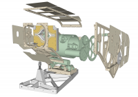
During the past few weeks I've added the front inset bulkhead (through which the boom or arm protrudes) with nearby boom-retract limit microswitch, plus the exterior skin panels of the Surface Sampler Acquisition Assembly (SSAA) housing frames. The SSA looks a bit more complete at this point (even though it's empty). Also added are the pedestal base on which the SSAA sits and the yoke gimbal mount (more details in next reply).
|
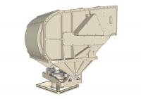
|
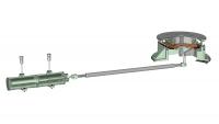
Posted by: Tom Dahl May 20 2017, 03:59 PM
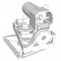
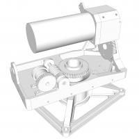
Here are close-ups of the pedestal base and yoke gimbal mount, which includes the azimuth and elevation drive assemblies, for the Viking lander's surface sampler's housing. The gear train for the azimuth drive (horizontally-arranged gearing, on the left) is based on a drawing of the actual hardware though the tooth counts and dimensions are estimated. The vertically-oriented elevation drive has an approximately-correct fixed worm-wheel gear, but the spur and bevel gears inside the little gearbox are speculative due to lack of reference documentation. The gear tooth profiles are simplified. The large cylinder is a very rough model of the drive motor for the elevation axis.
|
|
Posted by: Tom Dahl Jun 27 2017, 12:01 AM
Next up are the components of the boom extend-retract drive mechanism and the boom stowage drum for the lander's Surface Sampler Acquisition Assembly, in approximate form due to lack of detailed reference material (as denoted by the green tint). The hollow interior of the large drum contained a few feet of the Flat Conductor Cable (FCC) that runs through the middle of the boom (not shown here, but see earlier replies for renderings of it). This slack allows the boom to extend and retract by ten feet, as the slack within the drum is wound clockwise around the stationary hub when at one end of full travel, and re-wraps to be counter-clockwise around the hub by the time the other end of travel is reached. The flattened boom itself wraps around the exterior of the drum. The large slot in the drum (visible in the second image) allows the FCC to pass from the boom into the drum, and the slot in the hub (partly visible in the first image bracketed by curled bend-limiter fences) allows the FCC to exit the assembly through the center of the hub (coming out on the side visible in the third image).
|
|
|
Posted by: PaulH51 Jun 27 2017, 09:45 AM
Wonderful stuff.... Thanks for sharing this with us here... Thinking out loud, I wonder if we'll ever see any of the Mars rovers in this or similar format
Probably not in my lifetime...Posted by: monty python Jun 28 2017, 05:31 AM
Thanks. Always wondered how that worked.
Posted by: Tom Dahl Aug 4 2017, 04:14 PM
The Viking lander's Surface Sampler Acquisition Assembly (SSAA) is complete, for now at least. The https://3dwarehouse.sketchup.com/model/7bf78edb-6655-4c80-9ad9-8632f2abcac8/Viking-Lander-Surface-Sampler-Acquisition-Assembly is available at the 3D Warehouse. The final set of components to be finished included the boom supports and guides:
|
|
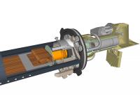
Here is the overall lander (still missing most external components) with the SSAA and its Collector Head in place (the second view shows the collector head fully retracted):
|
|
This view shows the surface sampler with its Collector Head Shroud Unit (CHSU) attached and configured for launch, cruise to Mars, and landing wherein the SSAA is pivoted down to engage the triangular restraint post. The CHSU sealed the ultra-clean and sterilized collector head:
|
Posted by: Tom Dahl Jan 14 2018, 12:37 AM
I've completed a detailed (nearly 18 minutes long) https://youtu.be/4c5o6jaJOuI that demonstrates operation of the Viking lander's Surface Sampler Acquisition Assembly. The video features the 3D digital model of the lander that I've been working on for the past few years (and which has a few more years to go until completion), described in earlier replies.
My thanks to the following organizations who have allowed me to research their Viking artifacts:
https://vikingpreservationproject.org
http://www.museumofflight.org
https://californiasciencecenter.org
http://www.vasc.org
https://www.nasa.gov/langley
https://airandspace.si.edu
Posted by: vikingmars Jan 14 2018, 08:37 AM
My thanks to the following organizations who have allowed me to research their Viking artifacts:
https://vikingpreservationproject.org
http://www.museumofflight.org
https://californiasciencecenter.org
http://www.vasc.org
https://www.nasa.gov/langley
https://airandspace.si.edu
WOW ! Thanks so much Tom for this astounding video: lots of congratulations to you
I feel being back at JPL and I'm remembering a lot of events !
|
Posted by: monty python Jan 14 2018, 09:14 AM
Tom, that is fantastic! I am old enough to remember those missions, and have always wondered how those arms worked.
Thank you for being such a Viking fan and for your hard work.
Posted by: Floyd Jan 14 2018, 03:24 PM
Tom, thank you for a fantastic movie. It is visually striking and extremely informative. The details of how the ten foot arm roles up are ingenious. I would think this movie would be particularly valuable for engineering courses to show how design translates into function---with details from two of the most iconic space craft ever. The description, narration and music all incredibly well done.
Posted by: john_s Jan 26 2018, 09:23 PM
Beautiful engineering, beautifully rendered and presented. Congratulations!
John
Posted by: PFK Jan 27 2018, 11:44 AM
As a humble chemist (albeit one who vividly remembers reports of the mission at the time and the pictures splashed across newspaper front pages) I have to say I'm blown away by this. Brilliantly informative and impressive stuff!
Posted by: Tom Dahl Jan 9 2019, 12:51 AM
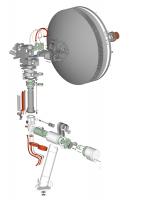
The next chapter in the effort to create a high-fidelity Viking '75 Mars lander 3D digital model is complete - the S-Band https://3dwarehouse.sketchup.com/model/4c0d0d3b-a1d9-4d81-9453-63d912fe27a0/Viking-75-Mars-Lander-High-Gain-Antenna-Direct-Communications-System (HGA) and its https://3dwarehouse.sketchup.com/model/f1b84d8e-7062-428f-ba59-549df33ae2ce/Viking-75-Mars-Lander-High-Gain-Antenna-Deployment-Mechanism (the preceding links lead to the SketchUp https://3dwarehouse.sketchup.com/user/u6e66c350-32eb-4e02-a5c5-ae6a9e4c3ac3/Tom-D?nav=models where the model files are freely available). Here are images comparing the model to actual antenna units:
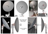
|
|
Here are exploded and cut-away views of the antenna:
|
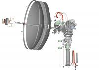
|
|
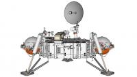
And an overall view of the work-in-progress lander model with antenna in place (most of the lander's external components are yet to be modeled):
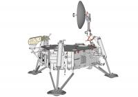
|
All externally-visible piece-parts of the HGA and deployment mechanism (along with a selection of internal parts for which I've found some documentation) are modeled in detail - nearly 300 in all. A https://goo.gl/photos/bcdFG1M2YMwQqyfq9 contains renderings of the model as progress has been made over the past few years (newer at the bottom).
Sincere thanks to the https://vikingpreservationproject.org, who allowed me many hours of access in 2015 and 2017 to HGA serial number 21 in their collection. I was able to capture hundreds of detail measurements with precision calipers along with hundreds of close-up photographs to guide the model during two trips from my home in Massachusetts USA to the VMMEPP in the Pacific Northwest.
Posted by: PaulH51 Jan 9 2019, 01:31 AM
I'm going to need more time to look at these in great detail.... wonderful stuff... Thank you Tom.
Posted by: sittingduck Jan 9 2019, 03:41 PM
Tom, what you're doing is not only historical preservation, but a work of art.
I wish you the best of luck in continuing the effort.
Posted by: Tom Dahl Oct 3 2019, 02:12 AM
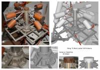
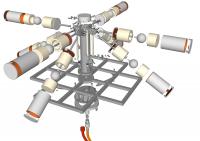
I've completed the remaining two communications antennas of the Viking '75 Mars lander: the S-band Low Gain Antenna (LGA) and the UHF antenna. The LGA was small a receive-only antenna used to pick up commands sent from Earth. Here are rendering of the LGA (https://3dwarehouse.sketchup.com/model/648d8c07-f99e-493a-99b0-35fc5d1f5e51/Viking-75-Mars-Lander-Low-Gain-Antenna):
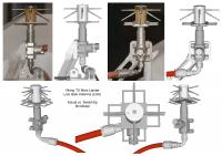
|
|
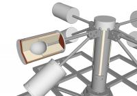
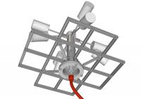
The UHF antenna was used to relay information from the lander through either of the two Viking orbiters and onward to Earth (which could be done either in real-time or deferred via the orbiter's tape recorder). Here are renderings of the UHF antenna (https://3dwarehouse.sketchup.com/model/443644b3-8b73-41cf-8934-56f5ac32951d/Viking-75-Mars-Lander-UHF-Antenna):
|
|
|
|
Posted by: scalbers Oct 3 2019, 09:56 PM
Nice to see these antennas again. I especially recall the LGA from the downlinked images. Thanks Tom!
Posted by: mcaplinger Apr 2 2020, 07:46 PM
Over on nasawatch it's being claimed that the NASA worm logo appeared on the Viking lander, but I couldn't find any evidence of this. Bicentennial logo, yes, Viking patch logo, yes, American flag, yes, but no obvious worm. Maybe there's a small one on the patch? I couldn't find any high-res images of the patch as it appeared on the lander. Anyone know?
Posted by: climber Apr 2 2020, 08:49 PM
What about a PM message to Olivier? I mean Vikingmars
Posted by: atomoid Apr 2 2020, 10:13 PM
its already April 2nd, so what the heck is the NASA "worm" logo? so i found this https://arstechnica.com/science/2020/04/nasa-brings-its-iconic-worm-logo-back-to-mark-return-of-human-spaceflight/ article. This https://www.nasa.gov/audience/forstudents/5-8/features/symbols-of-nasa.html says it was used from 1975 to 1992, so guessing everything on the lander would have been finalized before then, so no probably not on Viking hardware. 
Posted by: Tom Dahl Apr 2 2020, 10:57 PM
As far as I know, the NASA "worm" logo did not appear on the Viking landers. As mentioned, the wind covers for the two Radioisotope Thermoelectric Generators on each lander sported an American flag, the US Bicentennial logo, and the patch designed by Peter Purol. The Proof Test Capsule lander at the Smithsonian National Air and Space Museum has a good representation of the Flight wind cover decorations:
|
Here is better view of Peter's patch (which reveals no worm logo):
|
Posted by: Tom Dahl Jul 8 2020, 12:02 PM
I have completed a 22-minute video that describes the Viking lander's three https://youtu.be/ISRnnCQG06I in detail (UHF relay antenna for transmitting to either Viking orbiter, S-Band Low Gain Antenna for direct reception from Earth, S-Band High Gain Antenna for direct transmission and reception to/from Earth). I hope that people find it interesting.
Posted by: Tom Dahl Apr 18 2021, 02:42 AM
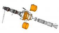
The latest addition to my work-in-progress Viking '75 Mars lander 3D digital model is the propellant- or fuel-system tanks, valves, piping, and the MR-50F roll-control thrusters that are mounted on the fuel tanks. The digital model is freely available via DropBox as a https://www.dropbox.com/s/ulbw4ukmvbfyc6g/Viking%20Lander.skp?dl=0 model file.
|
|
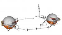
|
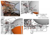
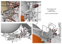
The following montage compares the 3D model with the test lander at the https://vasc.org. That unit has slightly different piping compared to the two Flight landers, and it is missing the 1/4-inch serpentine line that connects the two roll-control thrusters on each fuel tank.
|
Posted by: Tom Dahl Apr 18 2021, 02:53 AM
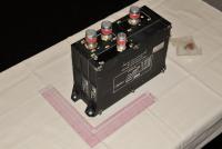
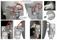
Here are detailed views of the MR-50F roll-control thrusters, made by Rocket Research Company (now part of Aerojet Rocketdyne), with solenoid valves by Parker Hannifin. The thrusters were used during the final minute of landing on Mars to orient the lander such that it would point in a desired azimuth in its landed location to optimize mid-day solar illumination in "front" of the lander where the two cameras had best coverage of the Mars surface.
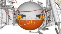
|
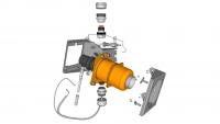
|
|
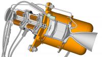
|
Posted by: Tom Dahl Apr 18 2021, 03:08 AM
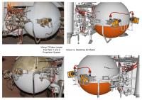
Here are details of the pair of main valves on each of the lander's two fuel tanks. First the valves and lines for fuel tank 1:
|
The valves and lines for fuel tank 2:
|
And details with exploded view of the main valve pair on fuel tank 1 (the main valves on fuel tank 2 are inverted from this arrangement). The valve on the right (upright T) is Normally-Open (NO), allowing fuel to flow through the 0.75 inch fuel line (tube) leading from the bottom of the fuel tank. When pyrotechnically triggered, the NO valve will permanently close, blocking the flow of fuel upon landing. The valve on the left (inverted T) is Normally-Closed (NC), preventing fuel from flowing from the tank toward the lander's three Terminal Descent Engines (TDEs). When pyrotechnically triggered, the NC valve will permanently open, allowing the flow of fuel to reach the TDEs during descent to Mars. During the mission the NC valve triggers first, opening to allow fuel to flow (through the already-open NO valve and then the now-open NC valve). At landing, the NO valve triggers second, closing to ensure the TDEs shut down.
|
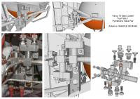
Posted by: Tom Dahl Oct 23 2021, 12:38 AM
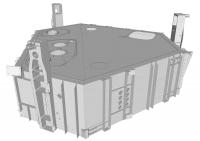
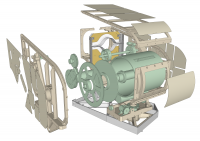
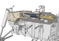
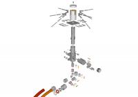
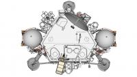
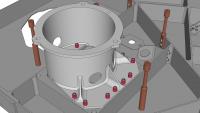
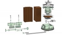
I have been adding some major internal components to the Viking '75 Mars lander 3D digital model, including the large Equipment Plate that spans most of the upper interior of the lander. The Equipment Plate is a one-piece aluminum machined unit which is supported by nine titanium fittings attached to the sides of the lander body. Most of the lander's interior equipment (batteries, power control, tape recorder, science instruments, computer, communications assemblies) are bolted to the bottom surface of the Equipment Plate and hang down below it within the volume of the lander body. Here is an overall view of the lander body and equipment plate, without the lander's top dust cover.
|
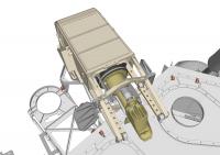
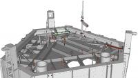
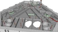
Here is an above view of the equipment plate and attached components, including those nine titanium support fittings arranged around the plate's perimeter. The little red cylinders are standoffs to support the lander body top dust cover.
|
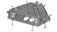
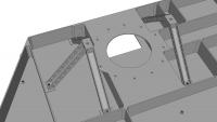
Here is a below view of the equipment plate, which is relatively plain. It does show the portion of the serpentine coolant loop which was attached to the underside of the plate. The coolant loop was used prior to launch to circulate chilled water around the lander's two Radioisotope Thermoelectric Generators (RTGs), which produced more excess heat under Earth seal-level conditions than the lander was designed to sustain. As seen here, the loop also traveled around the equipment plate to reduce internal lander temperatures.
|
Here is a detail view of one of the two camera mount adapters bolted to the top of the equipment plate, to which a camera was attached on top of the lander (this is the mount for camera #1). The little red fasteners are Hi-Lok collars, a specialized type of nut that was used extensively in assembling the lander. The collars work with Hi-Lok pins, a type of bolt. Along with a special installation tool, the Hi-Lok pins and collars can be installed in situations with limited access to the bolt-side of the fastener. The tip of the pin has a hex recess; the installation tool uses this to prevent the pin from rotating when the collar is tightened.
|
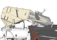
This detail view shows a small tripod and bipod attached to the equipment plate's upper surface. These supported the inboard side of RTG #2; the outboard side was supported by the upper edge of the adjacent lander body side beam (not shown in this image, but visible in the first image above). A similar tripod-bipod pair for supporting RTG #1 is located across the equipment plate.
|
Posted by: vikingmars Oct 25 2021, 10:02 PM
Here is an above view of the equipment plate and attached components, including those nine titanium support fittings arranged around the plate's perimeter. The little red cylinders are standoffs to support the lander body top dust cover.
Here is a below view of the equipment plate, which is relatively plain. It does show the portion of the serpentine coolant loop which was attached to the underside of the plate. The coolant loop was used prior to launch to circulate chilled water around the lander's two Radioisotope Thermoelectric Generators (RTGs), which produced more excess heat under Earth seal-level conditions than the lander was designed to sustain. As seen here, the loop also traveled around the equipment plate to reduce internal lander temperatures.
Here is a detail view of one of the two camera mount adapters bolted to the top of the equipment plate, to which a camera was attached on top of the lander (this is the mount for camera #1). The little red fasteners are Hi-Lok collars, a specialized type of nut that was used extensively in assembling the lander. The collars work with Hi-Lok pins, a type of bolt. Along with a special installation tool, the Hi-Lok pins and collars can be installed in situations with limited access to the bolt-side of the fastener. The tip of the pin has a hex recess; the installation tool uses this to prevent the pin from rotating when the collar is tightened.
This detail view shows a small tripod and bipod attached to the equipment plate's upper surface. These supported the inboard side of RTG #2; the outboard side was supported by the upper edge of the adjacent lander body side beam (not shown in this image, but visible in the first image above). A similar tripod-bipod pair for supporting RTG #1 is located across the equipment plate.
What a GREAT work ! Thank you so much Tom
Posted by: Tom Dahl May 19 2022, 10:39 PM
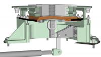
The next Viking lander component 3D models to be completed represent the lander's two thermal switches, which were mounted on the upper surface of the lander's Equipment Plate (the subject of my prior post above). The thermal switches are seen here as green-tinted boxy objects (the contactor assembly) connected to horizontal cylinders (the actuator assembly), on the left and right sides of the rendering. The green coloration represents the fact that I don't have exact measurements for these components.
|
The purpose of each thermal switch was to permit and regulate the transfer of heat from the Radioisotope Thermoelectric Generator (RTG, not shown) mounted directly above the switch contactor assembly, into the lander interior. The near-surface atmospheric temperature of Mars, as measured by the Viking landers, varied from about 1F during a summer day to -178F during a winter night. Most of the lander's components, including electronics and especially its rechargeable batteries, would not survive well-below-freezing temperatures. The RTG's housing exterior was at a fairly steady temperature of about 330F (thanks to the natural radioactive decay of plutonium contained in the RTG's internal fuel capsule), and the lander was designed to utilize that heat to maintain adequate internal temperatures. During cold periods the thermal switch actuator would close the thermal switch, forming a thermally-conductive path between the bottom of the RTG and the lander's internal Equipment Plate. During relatively warm periods, the actuator would open the switch, interrupting the high-conductivity path and allowing relatively little heat to flow into the lander.
When the RTGs were installed onto the landers prior to launch, Earth's relatively dense sea-level atmosphere provided an excess of available heating during the final months prior to launch. Even with the thermal switches open, there was too much heating. Therefore, a coolant loop was incorporated into the lander which circulated chilled water through End Cap Coolers mounted on top of and below each RTG. The top side of the thermal switch contactor assembly was hard-bolted to the underside of the corresponding RTG's lower End Cap Cooler. The bottom of the contactor assembly was hard-bolted to a platform machined into the Equipment Plate.
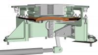
Here is a cut-away view of a thermal switch with actuator assembly on the left and contactor assembly on the right, connected via a linkage that transmitted the horizontal movement of a piston within the actuator to the contactor.
|
Here is an exploded view of a thermal switch. The brown objects in two stacks at center are 0.001 inch thick copper foils, 100 per stack. These foils are the core of the conductive path. In the assembled thermal switch, the stacks are interleaved forming a 200-foil group (visible in the middle of the exploded contactor on the right). The foils are bonded together where they overlap at center, and also at their ends, forming a cross with short flexible arms.
|
Here is a close-up of the cut-away actuator assembly. Freon gas filled the volume surrounding the two bellows chambers. When warmed, the freon expanded and pushed the central piston to the right. The piston pushed the linkage rod which connects the actuator to the contactor via clevises at both linkage ends.

|
Here are close-up cut-away views of the contactor assembly, first showing the closed configuration and then as opened. The central area of the stack of copper flexible foils is moved up (when closed) and down (when open) via a bellcrank driven from the actuator assembly by the linkage rod. A layer of highly-conductive tin is cast on top of the foil stack. When the switch is closed, the tin "seat" presses hard against the underside of a very thick block called the platten (at top-center of the images, with a vertical thread hole). The platten is hard bolted to the lower End Cap Cooler, upon which is mounted the hot RTG housing itself. Heat from the RTG flows downward through the lower End Cap Cooler, the platten, the tin seat, and into the center of the stack of copper foils. The heat then flows sideways through the flexible foil arms and into the boxy lower base (tinted green, across the center of the image) of the contactor assembly. Because the base is hard-bolted to the Equipment Plate, heat flows into the plate and spreads throughout the upper part of the lander interior. The lander's internal temperature-sensitive components (computer, batteries etc.) are bolted to the underside of that plate and therefore receive heat.
When the switch is opened the central portion of the stack of copper foils moves downward, causing the tin seat to pull away from the bottom of the platten. While the platten remains permanently warm (as the RTG's plutonium fuel slowly decays over decades), relatively little heat is radiated from the platten to the seat and foils. The switch provides an effective 50:1 heat conductance ratio when closed vs. opened.
|
|
Lastly, here is an view of the underside of a thermal switch when mounted on the Equipment Plate.
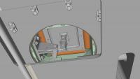
|
Posted by: scalbers Jan 2 2023, 07:43 PM
Here are a few recent photos of the spare flight qualified lander VL3, being prepared for exhibit at a museum in Oregon:
https://www.facebook.com/VikingMarsMission/photos/pcb.3227767737535008/3227767297535052/
Posted by: Tom Dahl Jan 3 2023, 12:31 AM
Indeed the Flight Capsule 3 or FC3/VL3 backup lander has moved from The Museum of Flight in Seattle where it was exhibited for many years, now to be exhibited at the Evergreen Aviation and Space Museum in McMinnville, OR. Hopefully the exhibit presentation will be informative and the lander will be as accessible as possible.
For what it's worth, I have visited the FC3 lander a number of times while it was exhibited at The Museum of Flight, including a visit with permission of the unit's owner (the https://vikingpreservationproject.org) and supervision by Museum staff that allowed me to capture many detailed measurements of various lander components. I have also taken hundreds of high-resolution detailed photographs of the unit, available in this https://goo.gl/photos/hedHCChRTyAbsN7W9.
Posted by: BYEMAN Jan 3 2023, 12:48 AM
Just wondering if anybody has come across a document(s) for the lander equivalent to "Viking 75 Orbiter System and Launch Operations Final Report". With emphasis on the launch operations.
Posted by: Tom Dahl Jan 4 2023, 02:46 AM
I'm not sure what kind of document focusing on the lander would be a good equivalent. There is the "https://ntrs.nasa.gov/citations/19770022101" by Martin Marietta. My copy is packed away due to a recent move but the scanned copy linked above on the NASA Technical Reports Server will reveal its full contents. There is also Martin Marietta's "Viking Lander `As Built` Performance Capabilities" which contains details about the actual capabilities of various lander systems (exact ratio transmitter powers, for example) but from memory (my copy is packed away) there is not a lot concerning launch. I have not found a copy on-line, so I'm sorry I can't help much in showing the document's content. I also have a copy of the two-volume document by General Dynamics "Viking AEC Safety Study, Phase I (Launch Vehicle Hardware, Launch Complex and Trajectory Data)" and "Viking AEC Safety Study, Phase II (Range Safety Equipment, Launch Pad Hazards, Launch Vehicle Failure Probabilities, and Reentry Environment)". These contain very detailed technical information for the Atomic Energy Commission (AEC) that addresses safety issues related to the Viking lander's plutonium-powered Radioisotope Thermoelectric Generators (RTGs).
The above documents plus others in my collection are informally https://goo.gl/photos/CjNUtwXwfFCgrBC57 in this Google Photos album. That catalog is out of date by a couple of years (I got lazy updating it as I acquired more material) but I don't have anything newer relating to the launch phase of the mission.
Posted by: Tom Dahl Jun 7 2023, 12:55 PM
I have recently completed modeling the Viking landers two Radioisotope Thermoelectric Generators (RTGs). Here are some overall views:
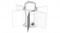
|
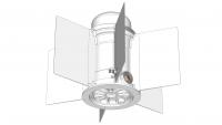
|
Here is an overall cut-away view of the RTG:
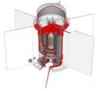
|
The RTGs are a Viking-specific variant of the SNAP-19 type which was used on earlier spacecraft (Nimbus III, Pioneer 10 and 11). SNAP is an acronym for https://en.wikipedia.org/wiki/Systems_for_Nuclear_Auxiliary_Power, which is a series of generators stretching back to the 1950s. Odd-numbered SNAP designs convert the heat of natural radioisotopic decay directly into electricity. Even-numbered designs contain a nuclear reactor in which a radioisotope undergoes accelerated nuclear fission; the resulting heat is converted into electricity in a variety of means.
The Viking SNAP-19 RTGs were fueled with Plutonium 238 in the form of Plutonium Dioxide Cermet (rather than the more hazardous pure Plutonium 238 metal), which is 83% PuO2 and 17% Molybdenum. The fuel was shaped into 18 discs or pucks, seen on the far left in the following exploded views:
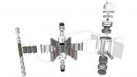
|
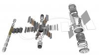
|
The RTG has no moving parts and is completely passive with no means of control. It weighs about 34 pounds and is a bit over 15 inches high (including the dome on top). The span of the six cooling fins is 23 inches across opposite pairs. There are 20,600 curies of fuel (equivalent to a few pounds) sufficient to generate 682 thermal watts from the heat of natural radioactive decay at the time of fueling (which was some nine months prior to launch). At the beginning of the mission the RTG produced about 42 watts of electricity at 4.4 volts DC. The conversion is quite inefficient but the generator has extreme reliability and robustness, and the excess heat was critical to the mission (heating the landers interior electronic components).
Electricity is generated via the https://en.wikipedia.org/wiki/Thermoelectric_effect, by which a temperature differential across a thermoelectric couple produces electricity. In the SNAP-19 generator there are a total of 90 thermoelectric conversion couples, each consisting of a P-leg and an N-leg:
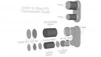
|
The P-leg materials are 15% a mix of Tellurium, Antimony, and Silver, and 85% a mix of Germanium and Tellurium, given the designation TAGS-85, plus a Tin-Tellurium segment on the hot side (on the right in the above image). The N-leg materials are a Lead-Tellurium mix designated 3M-TEGS- 2N(M).
The 90 couples are grouped into six thermoelectric conversion modules of 15 couples each. The following image shows two of the modules in exploded views:
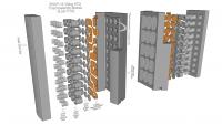
|
The couples are connected by copper straps. Pairs of couples are connected in parallel, and the pairs are connected in series. The couples in adjacent modules are interconnected by #9 gauge wires, forming a partial hex pattern above and below the RTG core that is visible in the overall exploded views. The full hex wire below the core is a magnetic compensation loop. The hot shoe (inboard end) of each couple is up against the graphite heat shield surrounding the fuel capsule (actually separated from the heat shield via a thin mica sheet for electrical insulation). The temperature of the heat shield surface - forming the hot side of the couple - is about 950F (about 510C). To maximize the temperature differential across the thermoelectric couples, a set of cold end hardware provides a thermally conductive path from the copper interconnect straps (which are soldered to the outboard ends of the P- and N-legs of the couples) to the relatively cool exterior RTG housing. The temperature of the exterior housing at the root of each of the six large cooling fins - which are directly adjacent to the six aluminum heat sink bars - is typically about 330F (about 160C).
Starting from the moment of assembly, the RTG power output gradually decreased due to a number of factors:
- Reduction in the RTG core temperature due to decay of the Plutonium fuel, reducing the temperature differential across the thermoelectric couples and thus the efficiency of the thermoelectric conversion process. With a half-life of about 88 years, this was actually not a significant factor during the expected single-digit-years lifetime of the mission.
- Sublimation loss of material from the thermoelectric conversion components due to continuous exposure to high heat.
- Increase in Helium gas within the RTG (produced spontaneously by decay of the Plutonium fuel). Helium has a relatively high thermal conductivity, which lessened the temperature difference across the thermoelectric couples and reduced their efficiency.
The effect of the Helium buildup was partly counteracted by a novel solution. The prominent dome on top of the generator, seen in section view in the following image, is a sealed reservoir filled with a 95% Argon / 5% Helium mix at assembly.
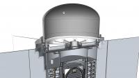
|
The generators cylindrical body was filled with a 90% Helium / 10% Argon mix. The initial high Helium fraction within the generator body was deliberately chosen to reduce the beginning-of-life power output. The months-long series of final RTG tests and storage prior to launch in Earths warm dense sea-level atmosphere would otherwise have produced RTG temperatures higher than desired. During cruise to Mars (in vacuum) and on the Mars surface (in a very cold low-pressure atmosphere) a higher energy conversion rate - and thus higher temperature differential - was wanted. The interface between the RTG body and reservoir dome was sealed as described earlier, but with an intentionally leaky seal. A dummy electrical receptacle with a Viton O-ring seal was installed between the body and dome. The dummy receptacle is the threaded object at top center of the ribbed RTG upper cover in the above section image. The O-ring permitted an extremely slow but effective gas exchange between RTG body and reservoir, raising the fraction of Argon (which is less thermally conductive than Helium) in the RTG and improving power generation.
A great deal of effort was applied to mitigate risks of Plutonium fuel release that might occur due to launch accidents (explosions) or unintended spacecraft reentry into Earths atmosphere (if the booster rocket did not impart sufficient Earth-escape launch velocity). The following cut-away image shows the RTGs heat source (as the encapsulated plutonium fuel assembly was termed) in close-up:
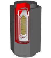
|
To mitigate the effect of physical shocks and impacts, the fuel stack (olive-drab pucks) was encapsulated in a four-layer metal capsule consisting of the following, from inner to outer:
- Inner Liner made of a Molybdenum-46% Rhenium alloy, 0.009 inch thick. This is formed of two slip-fit overlapping shells, in direct contact with the Plutonium fuel. (In order to exactly fill the volume of the capsule, Molybdenum shims were placed as needed between fuel pucks. The fuel capsule I modeled, VF-3, has five such shims, three of which are visible.)
- Liner made of a Tantalum-10% Tungsten alloy, 0.020 inch thick. This layer is welded closed and provides the main decontamination and health-physics encapsulation for the fuel.
- Strength Member made of T-111, a Tungsten-8% Hafnium-2% Tantalum alloy, 0.090 inch thick. This layer provides the primary impact resistance necessary in case the overall RTG or a separated fuel capsule fell from a great height onto a hard surface.
- Capsule Clad made of a Platinum-20% Rhodium alloy 0.018 inch think, providing an oxidation barrier during capsule handling. Handling difficulties were exacerbated by the fact that the capsules outer surface was thermally very hot - nearly 1400F (about 760C). (The core of the Plutonium was almost 1900F, 1040C.)
To mitigate the extreme heating that could occur if the RTG were to reenter the Earths atmosphere at nearly orbital speeds, the above capsule was first enclosed in three pyrolytic graphite sleeves, and then within a large hexagonal heat shield made of AXF-Ql fine grained isotropic Poco graphite, enclosed on both ends with graphite caps attached via stub Acme threads. The graphite is tolerant of extreme heating. In fact two earlier-version SNAP-19B RTGs were inadvertently subjected to moderate re-entry conditions when the NIMBUS B-1 spacecraft to which they were attached suffered a launch abort about one minute after liftoff in May 1968. The RTG housings were completely destroyed, but the heat sources were found and recovered from the Pacific ocean floor in October 1968 and examined in detail. The graphite heat shields were essentially intact.
The SNAP-19 Viking RTG is marvelously simple in principle but subtly designed for extreme reliability.
Posted by: Floyd Jun 7 2023, 02:43 PM
Thank you Tom. The models and writeup are outstanding. It is fascinating to see and read about all that went into making the RTG as reliable and safe (to accident) as possible.
Posted by: mcaplinger Jun 7 2023, 03:37 PM
Great post on the RTGs, Tom! Looking forward to seeing them integrated into the overall model. I've never been sure of exactly where they were, as they are underneath a cover and not shown well in most extent drawings and photos.
It's a little surprising to me that having the RTGs "inside" was the configuration they chose (with a "thermal switch"* to control the conduction between the RTG and the equipment plate). MSL and M2020, of course, have their RTGs outside with a fluid loop to bring in the heat. Seems like it would get pretty hot under the RTG cover.
* https://ntrs.nasa.gov/api/citations/19810001592/downloads/19810001592.pdf page 34.
Posted by: Tom Dahl Jun 7 2023, 11:08 PM
Indeed it surely was pretty hot within the lander's wind covers, given that the RTG exterior housings were over 300F continuously. Even so, the conduction and radiation of heat into the lander was not sufficient during cold winter nights, thus the need for thermal switches used to occasionally provide a higher-efficiency conduction path under each RTG's front edge. (An earlier reply above has details of those thermal switches.) I think the rationale for enclosing the Viking lander's RTGs was due to lack of knowledge of Martian surface winds, and to some extent of surface pressure and gas composition. The covers were a strategy to avoid loosing too much heat to worst-case estimated winds; the risk of over-heating was apparently deemed minimal.
Regarding the installation of the RTGs, I have almost completed modeling the associated wind covers and their internal framework and fasteners, the RTG Upper and Lower End Cap Coolers and their plumbing, etc. Here is a sneak peak at the RTGs and wind covers on a partial lander for context:
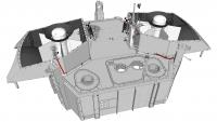
|
And here is a historic image from Martin Marietta showing the Proof Test Capsule lander (now in the Smithsonian National Air and Space Museum) without the wind cover tops. In this image instead of RTGs there are two ETGs installed - Electrically-heated Thermoelectric Generators: nearly identical to the RTGs but with an electric heater block instead of a Plutonium fuel capsule. The electric cable leading into the ETG reservoir dome is the indication of ETG vs. RTG.
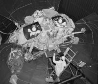
|
In both my 3D model rendering and the historic photo the black conical objects on top of the RTG/ETG (and within which the reservoir dome is situated) are Upper End Cap Coolers. You can see the coolant loop tubing that enters and exits the front edge of the cooler near the top of the RTG/ETG. The Lower End Cap Coolers are not visible due to the angle I chose in the 3D rendering, but one is barely visible under the left ETG in the historic photo. It is a black flat disc with a large cutout to accommodate the giant bulge in the wind cover bottom to avoid the fuel tank. An edge of the LECC is just visible at about the 7 o'clock position between ETG radiator fins.
In the historic photo the massive plastic-wrapped hoses that encircle the ETG on the right (and that snake around behind the lander) are providing the coolant to the lander's coolant loop. The internal path of the coolant loop is visible in some of my earlier 3D renderings in posts above.
Posted by: Tom Dahl Jul 15 2023, 06:57 PM
I have completed integrating the SNAP-19 Viking RTGs into my work-in-progress Viking '75 Mars lander 3D model. Here are renderings of the coolant loop, from above and below, that was used prior to launch to remove excess heat from the RTGs and lander interior. The RTGs directly generated electricity from the copious amount of heat produced by radioactive decay of plutonium 235 fuel within each RTG. The RTGs and associated integration mechanisms were designed for the Mars surface environment, which is very low pressure and quite cold. Earth's warm higher-pressure atmosphere caused excessive heating of the lander after the RTGs were installed during the final few months prior to launch. Sterilized chilled water was circulated through the loop almost without interruption (even during the lift of the shrouded orbiter and lander capsule onto the Titan launch vehicle) until shortly before launch. At that point, the coolant was purged with hot dry sterile nitrogen gas, and then a pyrotechnic cutter severed the lines within the Base Cover (top half of the inner layer of the lander capsule). This elaborate procedure was used to avoid unsealing the bioshield (outer layer of the capsule within which the sterilized lander was enclosed) and contaminating the lander with Earthly spores and microbes.
The large black objects affixed to the top and bottom of the RTGs (seen in transparent form to better reveal coolant loop components) are passive End Cap Coolers (ECCs). The coolant circulated through tubing embedded within the ECCs to carry away some RTG heat, and the large surface area of the conical upper ECC and the flat disk lower ECC radiated additional heat.
The loop was also used during the two-day complete-capsule sterilization procedure, temporarily replacing the chilled water with hot water to speed up heating the lander interior (otherwise the lander body's insulation would require a much longer heat soak period).
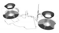
|
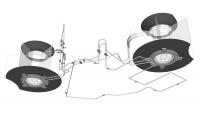
|
Here is an historic diagram of the coolant loop and N2 purge line (a simplified form of which is included in the model, see subsequent replies, but not shown above).
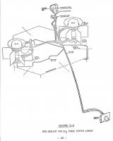
|
Posted by: Tom Dahl Jul 15 2023, 07:48 PM
Here are exploded views of the wind cover for RTG #2. The two wind covers are nearly-identical mirror images of each other. They differ primarily in small items attached to the front face of the wind cover, and that the top of wind cover #2 has an indentation for clearance of the Low Gain Antenna which is located very close to the wind cover. As can be seen, the wind covers are more complicated than they perhaps appear. Each wind cover has internal stiffening ribs along the side and an internal panel near front-center. Each wind cover has a large circular vent on its bottom face near a front corner (visible left of center in the second exploded view below). The vent allows equalization of pressure during launch from Earth and landing on Mars, and is covered with fine mesh to filter out most Martian atmospheric dust. Each wind cover has a camera Reference Test Chart (RTC) attached to its front face. The RTC itself is exploded in these views. A small skirt surrounds the sides and front of the wind cover bottom edge, to minimize build-up of Mars dust under the wind cover during the mission.
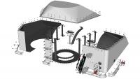
|
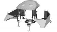
|
Here are close-up views of RTG 2 within its wind cover, starting with a top view. The large conical Upper End Cap Cooler (ECC) is prominent surrounding the reservoir dome atop the RTG housing. The rear rim of the ECC is clipped for clearance within the sloping top of the wind cover. The curving coolant loop inlet and outlet lines are prominent in the upper right of the image. The flat disc radiator fin of the lower ECC blends into the black interior of the wind cover bottom, but it is quite large and obvious when you know what to look for. The rear edge of the radiator fin is also clipped to clear the wind cover's large spherical inward-bulging rear which in turn provides clearance for the lander's nearby propellant tank. The large red cable in the lower right carries the 4.4 volt DC electric output of the RTG, along with six instrumentation signal lines (two each for an internal pressure transducer, a fin root thermistor which measured the temperature of the interior surface of the RTG housing, and a Resistive Temperature Detector (RTD) which measured the temperature of one of the thermocouple pairs surrounding the RTG's internal heat source). The small cream-colored cable passing through an electrical connector near bottom-center delivers the signal from a hazard monitor thermistor which measured the exterior temperature of the RTG housing.
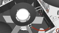
|
Here is a side view of RTG and wind cover 2 that is cut away to reveal RTG mounting details. The lower ECC has a flattish gray (I believe cast aluminum) body with a somewhat irregular shape. The coolant loop lines enter and exit from the right portion of the ECC body. Four stout tabs (only one of which is easily visible here below-center of the image) mount the ECC, and thus the RTG and wind cover, to the lander structure. The ECC's two inboard tabs are supported on titanium (for low thermal conductance) U-channel tripods and bipods (with lightening holes) that are in turn mounted to the Equipment Plate within the upper interior of the lander. The green-tinted object between the tripod and bipod and below the RTG front edge is a Thermal Switch for transferring variable amounts of RTG heat into the lander. The ECC's two outboard tabs bolt to small extensions of the lander body side beam structure. The lower ECC's flat disc radiator fin is cut away to better reveal the ECC body below the fin. The disc fin is thin on its outer perimeter, thickening toward its slightly depressed center.
The dark conical upper ECC is easily visible atop the RTG housing, and the coolant loop inlet and outlet lines can be seen passing into the upper ECC base. The larger-diameter striped segments of the coolant loop represent braided flexible hoses used in that area. The remainder of the coolant loop is rigid 0.25 inch tubing.
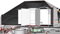
|
Posted by: Tom Dahl Jul 15 2023, 07:51 PM
Here are renderings of the entire RTG installation of the work-in-progress lander model, without the RTG wind cover tops to reveal the RTGs and details within. Compare these to a historic photo posted a few replies back.
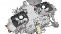
|
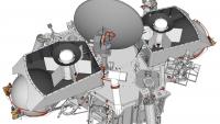
|
Posted by: Tom Dahl Jul 15 2023, 07:56 PM
Lastly (for now!) here is an overall view of the work-in-progress lander. Various exterior components remain to be modeled, which will keep me occupied for a few more years (literally). I began the creating model in December 2013, so I'm coming up on the tenth anniversary of the project. The model is freely available as a https://www.dropbox.com/s/ulbw4ukmvbfyc6g/Viking%20Lander.skp?dl=0 hosted on DropBox (note: it is nearly 400MB).
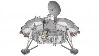
|
Posted by: rlorenz Jul 22 2023, 01:02 AM
And here is a historic image from Martin Marietta showing the Proof Test Capsule lander (now in the Smithsonian National Air and Space Museum) without the wind cover tops.
Amazing work, Tom. I'd never seen the RTG accommodation without the wind shields. Lots of other nice detail visible in your 3D model, like the little 'bone' energy absorbers attaching the leg bipod struts to the lander body....
Ralph
Posted by: Tom Dahl Dec 27 2023, 11:35 PM
I just completed a 21-minute video describing the Viking '75 Mars lander's two SNAP-19 Viking https://youtu.be/2ZnnzusE1mo (RTGs) in detail. The video illustrates the RTGs using a high-fidelity 3D digital model that is a work-in-progress hobby effort of mine (for the past ten years, as of this month), see earlier replies in this topic. The WIP digital model is freely available in SketchUp format via https://www.dropbox.com/s/ulbw4ukmvbfyc6g/Viking%20Lander.skp?dl=0 as a 386MB SKP format file.
I forgot to mention back in July that a few years ago I created a short video about the https://youtu.be/tKiiQpMdnTM, which mention those so-called load limiters.
Posted by: vikingmars Dec 28 2023, 12:58 PM
I forgot to mention back in July that a few years ago I created a short video about the https://youtu.be/tKiiQpMdnTM, which mention those so-called load limiters.
Dear Tom.
What an amazing work!
Congratulations: thanks to you, I'm travelling back in time.
With best regards,
Olivier
Posted by: john_s Dec 28 2023, 03:12 PM
Second that- wonderful and amazing stuff, and I learned a lot about how RTGs work.
John
Posted by: Glevesque Dec 30 2023, 05:28 PM
Very good job Tom Dahl. It truly is a technological marvel!
Powered by Invision Power Board (http://www.invisionboard.com)
© Invision Power Services (http://www.invisionpower.com)