Juno PDS data |

  |
Juno PDS data |
 Oct 9 2018, 11:02 PM Oct 9 2018, 11:02 PM
Post
#136
|
|
|
Senior Member  Group: Members Posts: 2511 Joined: 13-September 05 Member No.: 497 |
QUOTE (Brian Swift @ Oct 9 2018, 09:55 AM)  Mike, just curious, is there an explanation for the 20 msec START_TIME jitter... It's a software issue having to do with when the timestamp is captured relative to when the command to start imaging is sent. -------------------- Disclaimer: This post is based on public information only. Any opinions are my own.
|
 |
 
|
|
Oct 10 2018, 05:01 PM
Post
#137
|
|
|
Member Group: Members Posts: 403 Joined: 18-September 17 Member No.: 8250 |
QUOTE (mcaplinger @ Oct 9 2018, 04:02 PM) It's a software issue having to do with when the timestamp is captured relative to when the command to start imaging is sent. Is the the imaging electronics start signal linked to the spacecraft system clock or is it driven from some other free running asynchronous clock? My thinking being that if the start was linked to the spacecraft clock, the 20ms jitter would have a 1/256 sec (low precision spacecraft clock) quantization. So I could model actual start time as a 0 to 5 tick offset from the adjusted captured timestamp. |
|
|
|
|
Oct 10 2018, 06:20 PM
Post
#138
|
|
|
Senior Member Group: Members Posts: 2511 Joined: 13-September 05 Member No.: 497 |
QUOTE (Brian Swift @ Oct 10 2018, 09:01 AM) Is the the imaging electronics start signal linked to the spacecraft system clock or is it driven from some other free running asynchronous clock? Neither, sort of? It's complicated. The software sends the command to start imaging over a 57600 baud UART and that command is received and imaging starts based on the free-running oscillator in the JDEA. Meanwhile, back in the spacecraft computer, there is then a potentially variable delay before the timestamp is captured from the spacecraft clock. Yes, the spacecraft clock is quantized, but the delay is of order 20 msec for reasons having nothing to do with that. The delay could be 20 msec and it could be 40 msec and it could, perhaps, be anywhere in between or even longer. I don't think it can be shorter but I can't swear to that. I can't go into this in more detail, sorry. -------------------- Disclaimer: This post is based on public information only. Any opinions are my own.
|
|
|
|
|
Oct 10 2018, 11:58 PM
Post
#139
|
|
|
Member Group: Members Posts: 403 Joined: 18-September 17 Member No.: 8250 |
Thanks Mike, that answers my question. (Just not the answer I was hoping for.)
|
|
|
|
|
Oct 11 2018, 01:01 AM
Post
#140
|
|
|
Senior Member Group: Members Posts: 2511 Joined: 13-September 05 Member No.: 497 |
While I'm sure you appreciated this, it's worth noting that the uncertainty only applies to the START_TIME, the interframe time is set by the JDEA and has nothing to do with the spacecraft clock.
For on-orbit images, I've had some luck characterizing the START_TIME by doing limb fitting of the first image that contains the limb. It would be interesting to know if there are any systematics of the error, but none were apparent in my brief look at it. The cruise star imaging appeared to be behaving differently with regard to the error. -------------------- Disclaimer: This post is based on public information only. Any opinions are my own.
|
|
|
|
|
Oct 13 2018, 08:53 PM
Post
#141
|
|
 IMG to PNG GOD Group: Moderator Posts: 2250 Joined: 19-February 04 From: Near fire and ice Member No.: 38 |
QUOTE (mcaplinger @ Oct 11 2018, 01:01 AM) For on-orbit images, I've had some luck characterizing the START_TIME by doing limb fitting of the first image that contains the limb. It would be interesting to know if there are any systematics of the error, but none were apparent in my brief look at it. The cruise star imaging appeared to be behaving differently with regard to the error. This is exactly what I've been doing. Following this I also do limb fitting of the last image containing the limb and then adjust the interframe delay slightly if necessary (I typically end up with values like 0.3711 or 0.3708 or something like that instead of 0.371). After I fixed a bug in my software several months ago and another relatively minor and obscure bug last month this usually is sufficient and no further adjustments are necessary. However, I sometimes need to adjust the pointing by something like ±3 pixels in the horizontal direction in the really hi-res images. This might be because an SPK kernel containing the reconstructed PJ15 trajectory wasn't available (it is now). Also the images of the northern hemisphere are sometimes slightly problematic. It's as if the spacecraft orientation changes slightly during image acquisition but of course that's highly unlikely. I'm still working on this particular problem (apparently it's the only problem left in my processing pipeline). This doesn't cause any color channel misalignments though so it's not a big inconvenience. As a 'sanity check' it would be interesting to know which START_TIME value you got for an image or two, especially for images obtained at an altitude of ~25,000 km or closer. |
|
|
|
|
Oct 26 2018, 10:16 PM
Post
#142
|
||||
 Senior Member Group: Moderator Posts: 3231 Joined: 11-February 04 From: Tucson, AZ Member No.: 23 |
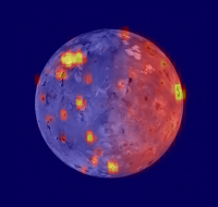
PJ11 and PJ12 data is now in the PDS (or at least the JIRAM data is available)
-------------------- &@^^!% Jim! I'm a geologist, not a physicist!
The Gish Bar Times - A Blog all about Jupiter's Moon Io |
|||
|
|
|
|||
|
Feb 4 2019, 10:40 PM
Post
#143
|
|
|
Member Group: Members Posts: 403 Joined: 18-September 17 Member No.: 8250 |
Juno3D, a JunoCam raw to textured 3D object processing pipeline implemented in Mathematica is available under permissive open source license at https://github.com/BrianSwift/JunoCam/tree/master/Juno3D
Sample outputs produced from an Earth flyby image are also available in the github directory. What it does... Converts Junocam raw image and metadata to 3D object suitable for importing into 3rd party rendering application (such as Blender). Input is MissionJuno website formatted -raw.png or PDS .IMG or .IMG.gz raw image file, and .json or .LBL metadata file. Output is Wavefront geometry and material file (.obj, .mtl) and an image/texture file for each color (.png). Raw image files and metadata are imported, SPICE and the camera model are used to map image pixels to a tessellated representation of the target (Jupiter) surface. Imagery that doesn't intercept the target is projected onto a backstop surface (large sphere centered at a spacecraft location with radius less than the distance to the limb.) Texture mapped geometry is written out. Information useful for rendering scenes (such as spacecraft position and Blender camera rotation values) is included as comments in the .obj file (which is a textual format.) By default flat field adjustment and linear light to sRGB are performed on generated imagery textures. These sRGB encoded textures provide a close representation of actual Jupiter contrast and may need post-processing in a tool like Photoshop to enhance details in the cloud structures. Can mark SPICE computed limb locations in texture images. The current lens model uses Brown-Conrady K1,K2,Xp,Yp plus linear and cubic CA terms. The output structure of a separate set of geometry for each of the three colors requires non-default shader/material and rendering options described below in Rendering in 3rd party application . Rendering in 3rd party application The 3D object produced by this script has three separate but co-located groups of geometry. Each set of geometry is textured with imagery for a different color channel. Each set of geometry has different triangle vertex locations, so the geometry associated with each color channel consists of triangles that are both inter-penetrating and nearly co-planar with the geometry from the other color channels. Therefore, each set of geometry must effectively be rendered independently to the red/green/blue channels of the final image. The above organisation means there is no spatial resampling of the raw data performed by this script. Thus, lens correction and perspective projection are accomplished in a single resampling done in the renderer. Step by step instructions to setup this rendering configuration in Blender and Apple XCode SceneKit Viewer are available in the Mathematica notebook. The Blender setup process is also available as a screen recording on YouTube at: https://youtu.be/6Wx--D_OxbI If you don't have Mathematica, the source code can still be viewed with correct formatting using Wolfram CDF Player available at https://www.wolfram.com/cdf-player/ Earth flyby image rendered in Blender at 45.51 pixels/deg: 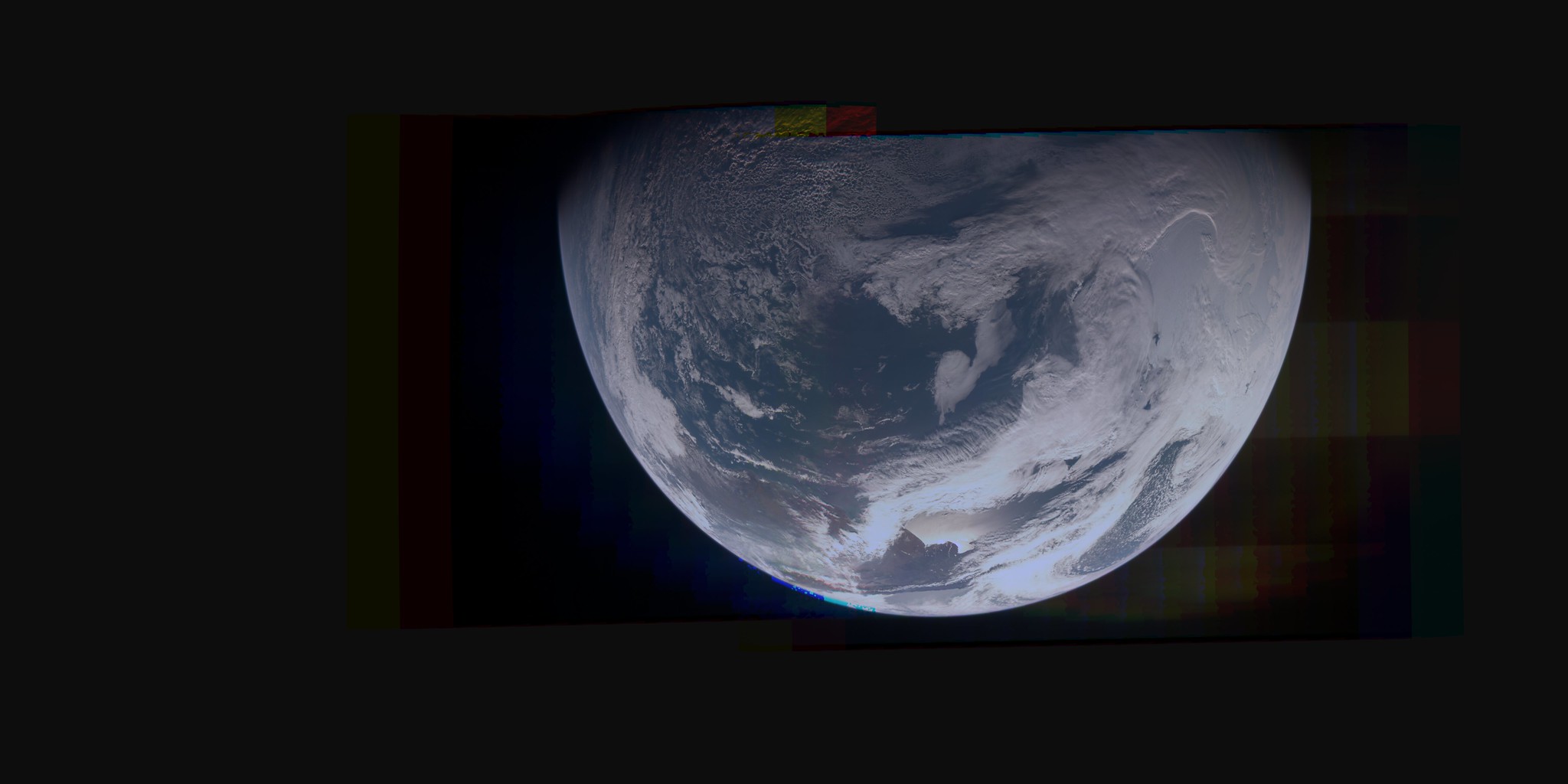
|
|
|
|
|
Feb 5 2019, 07:00 AM
Post
#144
|
|
|
Member Group: Members Posts: 403 Joined: 18-September 17 Member No.: 8250 |
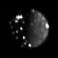
QUOTE (Bjorn Jonsson @ Oct 13 2018, 12:53 PM) This is exactly what I've been doing. Following this I also do limb fitting of the last image containing the limb and then adjust the interframe delay slightly if necessary (I typically end up with values like 0.3711 or 0.3708 or something like that instead of 0.371). ... As a 'sanity check' it would be interesting to know which START_TIME value you got for an image or two, especially for images obtained at an altitude of ~25,000 km or closer. Instead of limb fitting for start time and inter frame delay, have you considered fitting for start time and planet radius? I believe the Junocam visible limb is at a higher elevation than the 1-bar limb returned by SPICE. For example, in the occultation of Io in PJ16_11, SPICE (Web GeoGalc) predicts a start time of 2018-10-29T20:50:43.855 which is almost a second later than the image time of frame 8, 20:50:42.932. However, the image shows the visible limb already covering about 1/3 of Io. I've only done a few fits since my process isn't fully automated yet, but here are some preliminary results: Radius increase (km), start time adjustment, image id, frame numbers used for fit, filter 95 -.013 PJ14_19 7,31 green 47 -.004 PJ14_25 13,29 green 45 -.004 PJ14_25 7,35 green 90 .0015 PJ16_11 7,31 red 95 .0020 PJ16_11 8,33 green 90 .0005 PJ16_11 12,33 blue I have no reason to expect the height variation to be uniform across Jupiter, and can think of enough potential effects on it to eliminate any desire on my part to attempt to model it. Also, the time offsets above could all be shifted by constant, since my camera model has its own spacecraft to CCD frame transform. Mike - are you able to request a specific Juno spin phasing to ensure JunoCam is pointing in the right direction for a time critical event like PJ16_11 Io occultation? (I think if this image was 15 seconds earlier Io would still be some distance from the limb, and 15 seconds later it would have been completely covered) If so, that's pretty cool, if not, it's good to get lucky. |
|
|
|
|
Feb 5 2019, 02:42 PM
Post
#145
|
|
|
Senior Member Group: Members Posts: 2346 Joined: 7-December 12 Member No.: 6780 |
QUOTE (Brian Swift @ Feb 5 2019, 08:00 AM) I have no reason to expect the height variation to be uniform across Jupiter, and can think of enough potential effects on it to eliminate any desire on my part to attempt to model it. Jupiter's gravitational equipotential deviates by up to about 40 km from the IAU ellipsoid in a non-trivial way. Locally, there are also translucent or opaque haze layers of up to about three scale heights. We don't know the exact pressure of the level of the cloud tops. |
|
|
|
|
Feb 5 2019, 05:04 PM
Post
#146
|
||
|
Member Group: Members Posts: 890 Joined: 18-November 08 Member No.: 4489 |
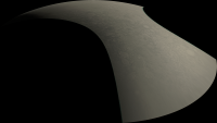
isis 3.6 now has a import tool "junocam2isis"
then use the standard isis3 pipeline a random EDR image test "JNCE_2018038_11C00011_V01"
near the northpole in orthographic projection , then minor image enhancing in gimp using gmic |
|
|
|
|
|
|
Feb 5 2019, 07:01 PM
Post
#147
|
|
|
Member Group: Members Posts: 403 Joined: 18-September 17 Member No.: 8250 |
QUOTE (Gerald @ Feb 5 2019, 06:42 AM) Jupiter's gravitational equipotential deviates by up to about 40 km from the IAU ellipsoid in a non-trivial way.... Thanks Gerald, was I curious about the magnitude of gravitational equipotential. Can you point me a reference for the 40km figure, or did you derive it from the published gravitational spherical harmonic values? |
|
|
|
|
Feb 5 2019, 08:11 PM
Post
#148
|
|
|
Member Group: Members Posts: 403 Joined: 18-September 17 Member No.: 8250 |
QUOTE (JohnVV @ Feb 5 2019, 09:04 AM) isis 3.6 now has a import tool "junocam2isis" then use the standard isis3 pipeline a random EDR image test "JNCE_2018038_11C00011_V01" ... near the northpole in orthographic projection , then minor image enhancing in gimp using gmic Cool John. Could you run JNCE_2013282_00C00102_V01 (this is the earth flyby image I used for an example above) I'm curious how ISIS compares to my processing. About how long does it take ISIS to produce the image? Do you know if ISIS is able to produce the final image with one image resampling or two? |
|
|
|
|
Feb 5 2019, 08:39 PM
Post
#149
|
|
|
Member Group: Members Posts: 890 Joined: 18-November 08 Member No.: 4489 |
i will grab "JNCE_2013282_00C00102_V01" tonight
isis has to remap in order to mosaic the parts together , simple cylindrical or Mercator projections are the ones normally used the above was then remapped to orthographic from Mercator so resampled from FULL res to 45.5111111111 <pixels/degree> ( a map that is 16384x8192 px) so a small 16k map for testing the tool , i did not want to take all night to run the set of tools 1)junocam2isis 2) spiceinit 3) cam2map ( took the longest time ) 4) automos 5) GDAL ( gdal_translate) |
|
|
|
|
Feb 5 2019, 08:55 PM
Post
#150
|
|
|
Senior Member Group: Members Posts: 2511 Joined: 13-September 05 Member No.: 497 |
QUOTE (Brian Swift @ Feb 4 2019, 11:00 PM) For example, in the occultation of Io in PJ16_11, SPICE (Web GeoGalc) predicts a start time of 2018-10-29T20:50:43.855 which is almost a second later than the image time of frame 8, 20:50:42.932. Using which SPICE kernels? Always important to make sure you are using the best reconstructions, the right SCLK-SCET, leapseconds, etc. QUOTE are you able to request a specific Juno spin phasing to ensure JunoCam is pointing in the right direction for a time critical event like PJ16_11 Io occultation? Wish I could take credit for this, but AFAIK we didn't even intentionally command an image for this event, much less a specific spin phasing, so it's all random chance. -------------------- Disclaimer: This post is based on public information only. Any opinions are my own.
|
|
|
|
|

|
Lo-Fi Version | Time is now: 19th April 2024 - 07:54 PM |
|
RULES AND GUIDELINES Please read the Forum Rules and Guidelines before posting. IMAGE COPYRIGHT |
OPINIONS AND MODERATION Opinions expressed on UnmannedSpaceflight.com are those of the individual posters and do not necessarily reflect the opinions of UnmannedSpaceflight.com or The Planetary Society. The all-volunteer UnmannedSpaceflight.com moderation team is wholly independent of The Planetary Society. The Planetary Society has no influence over decisions made by the UnmannedSpaceflight.com moderators. |
SUPPORT THE FORUM Unmannedspaceflight.com is funded by the Planetary Society. Please consider supporting our work and many other projects by donating to the Society or becoming a member. |
|