Creating images by interpolating between filters? |

  |
Creating images by interpolating between filters? |
 Oct 24 2010, 03:19 AM Oct 24 2010, 03:19 AM
Post
#1
|
|
 Junior Member  Group: Members Posts: 74 Joined: 9-October 10 From: Victoria, BC Member No.: 5483 |
This post by ugordan on my Ganymede mosaic intrigued me, and I just want to check something here.
It sounds like ugordan's software can just linearly interpolate between (say) a Green filter and a Violet filter image to create a (hopefully reasonably accurate) simulation of what a Blue filter image might look like - and then doing the same with other filters means that a simulated "true colour" image can be constructed. e.g. (use http://pds-rings.seti.org/voyager/iss/inst...a1.html#filters as a reference). Let's say we had a Green filter image and a Violet filter image of Ganymede where a given pixel had a DN (data number, or 8-bit pixel brightness, from 0 to 255) of 69 in Green and 51 in Violet. Green peaks at 585 nm and Violet peaks at 400 nm, and we want to interpolate an image taken with a Blue filter which would peak at 480 nm. Blue is 80/185 of the way between the two (on the Violet side), which means that the DN of that pixel in Blue should be (69-51)*(80/185)=7.78, or 8 DN higher than the Violet DN, which is a DN of 59. So if I create a program that can do that interpolation across the whole image, would the result be reasonably accurate simulation of an image actually taken with that filter ? That assumes of course that the surface responds linearly to visible light wavelengths, which isn't necessarily true. But then, I'm not wanting to do this for scientific analysis or anything - this is just for aesthetic purposes really, to try to construct simulated "true colour" images. And could it be possible to extrapolate a reasonably realistic Red filter image by seeing the difference between (say) Green and Orange and extending that further (linearly) into the red? Looking at this site it seems that the human eye's sensitivity peaks at 558, 531 and 419 nm for red, green and blue respectively, so (assuming this approach works) would interpolating to those wavelengths instead of the ones described in the ISS filter descriptions actually produce a result that is more like what the human eye would see rather than an eye tuned to Voyager's wavelengths? |
 |
 
|
|
Oct 24 2010, 10:55 AM
Post
#2
|
|
 Senior Member Group: Members Posts: 3648 Joined: 1-October 05 From: Croatia Member No.: 523 |
QUOTE (EDG @ Oct 24 2010, 05:19 AM)  It sounds like ugordan's software can just linearly interpolate between (say) a Green filter and a Violet filter image to create a (hopefully reasonably accurate) simulation of what a Blue filter image might look like - and then doing the same with other filters means that a simulated "true colour" image can be constructed. That's not really all I have in mind when I say interpolation. Indeed, if all you wanted to do is to approximate the appearance at a different wavelength you can do that by mixing channels in Photoshop. The difference between my code and this simple channel mixing is that I convolve that interpolated spectra (I think it's in 5 nm increments or something like that, can't check now) through the CIE XYZ tristimulus sensitivity curves. This turns a filter set with wavelengths A,B,C (or just 2 filters, but can also be more than 3) to their approximate color representation (approximate because I linearly interpolate the missing spectral curve points) in XYZ space. Then a conversion formula is used to turn those values into sRGB colorspace. This takes better care of colors that are otherwise hard to fit in the monitor gamut than simple channel mixing does. QUOTE So if I create a program that can do that interpolation across the whole image, would the result be reasonably accurate simulation of an image actually taken with that filter ? That assumes of course that the surface responds linearly to visible light wavelengths, which isn't necessarily true. But then, I'm not wanting to do this for scientific analysis or anything - this is just for aesthetic purposes really, to try to construct simulated "true colour" images. As I said above, you don't really need a program for that. As long as the spectra of the object of interest is relatively smooth and doesn't have large excursions in hue, you should be okay. If it does have large variations, like for example a strong blue (probably red as well) component, that's where differences start appearing. By way of XYZ calculations, a strong blue hue will also affect (suppress) the output sRGB red channel as the monitor gamut is limited. You don't get that with simple channel mixing. This isn't often the case with planetary bodies, but I've seen it while playing with Phoenix surface imagery. I couldn't get the "proper" color of the color calibration chips with channel mixing based on any "scientific" approach like interpolating target wavelengths. I haven't worked with Voyager Jupiter images so can't say if simple mixing can fix the fact the "green" filter is close to orange - it probably can, but here's an example of what that CIE XYZ interpolation gives as result for OGB color: http://www.unmannedspaceflight.com/index.p...st&p=162551 QUOTE And could it be possible to extrapolate a reasonably realistic Red filter image by seeing the difference between (say) Green and Orange and extending that further (linearly) into the red? Yes, although that increases noise as you're extending the linear segment as opposed to averaging two filters (like for example IR and green to get red). The same is obviously true for my code as well since that extrapolation step is essentially the same. I used that extrapolation from green and violet to get an approximately true color of Titania in this thread: http://www.unmannedspaceflight.com/index.p...st&p=163385 QUOTE Looking at this site it seems that the human eye's sensitivity peaks at 558, 531 and 419 nm for red, green and blue respectively, so (assuming this approach works) I'm not entirely sure of the exact wavelengths you should shoot for. I don't believe it's human eye sensitivity, I think it should be the sRGB gamut corner wavelengths or even the reference monitor phosphors if they're not the same. If you extrapolate for human sensitivity peak and then display it through sRGB phosphors, you don't really improve on the situation where you had spacecraft-specific filters and sRGB phosphors. Either way, the sets are mutually incompatible. -------------------- |
|
|
|
|
Jan 10 2012, 04:45 AM
Post
#3
|
||
|
Member Group: Members Posts: 808 Joined: 10-October 06 From: Maynard Mass USA Member No.: 1241 |
Based on the above threads and other sources, I've been
As we all know, the bandwidth of the MER filters are very narrow (20nm) which makes for narrowly saturated colors at their peak frequencies. I am also comparing some PDS calibrated images against their raw-jpgs. The hope is to get future raws-jpegs to look ... better.  -------------------- CLA CLL
|
|
|
|
|
|
|
Jan 16 2012, 01:01 AM
Post
#4
|
||
|
Member Group: Members Posts: 808 Joined: 10-October 06 From: Maynard Mass USA Member No.: 1241 |
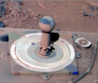
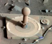
...color experiments continue... Here is Spirit's sundial on SOL 2102 (PDS data)
Spirit was embedded in Scamander Crater. The late afternoon sun and the tilt of the rover made the lighting dramatic. What really stands out to me, is the dust load on the sweep magnet.
-------------------- CLA CLL
|
|
|
|
|
|
|

|
Lo-Fi Version | Time is now: 19th April 2024 - 06:47 PM |
|
RULES AND GUIDELINES Please read the Forum Rules and Guidelines before posting. IMAGE COPYRIGHT |
OPINIONS AND MODERATION Opinions expressed on UnmannedSpaceflight.com are those of the individual posters and do not necessarily reflect the opinions of UnmannedSpaceflight.com or The Planetary Society. The all-volunteer UnmannedSpaceflight.com moderation team is wholly independent of The Planetary Society. The Planetary Society has no influence over decisions made by the UnmannedSpaceflight.com moderators. |
SUPPORT THE FORUM Unmannedspaceflight.com is funded by the Planetary Society. Please consider supporting our work and many other projects by donating to the Society or becoming a member. |
|