Juno Perijove 56, November 22, 2023 |

Juno Perijove 56, November 22, 2023 |
 Nov 29 2023, 09:24 PM Nov 29 2023, 09:24 PM
Post
#1
|
|
|
Senior Member  Group: Members Posts: 2517 Joined: 13-September 05 Member No.: 497 |
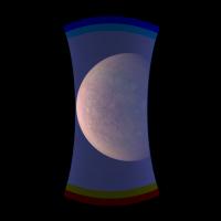
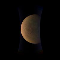
Some of the images have been posted on missionjuno.
You will immediately notice that there is something weird about them. Yes, we know about this, and I'll say more about it when I can. In the meantime, anything people can do to process them would be appreciated. I've had some success using https://github.com/chunglabmit/pystripe -------------------- Disclaimer: This post is based on public information only. Any opinions are my own.
|
 |
 
|
 |
|
Nov 29 2023, 09:35 PM
Post
#2
|
|||
|
Member Group: Members Posts: 143 Joined: 22-July 14 Member No.: 7220 |
QUOTE (mcaplinger @ Nov 29 2023, 05:24 PM)  Some of the images have been posted on missionjuno. You will immediately notice that there is something weird about them. Yes, we know about this, and I'll say more about it when I can. In the meantime, anything people can do to process them would be appreciated. I've had some success using https://github.com/chunglabmit/pystripe Oh, yeah, this is pretty bad. And subtracting the noise does not leave a lot of room for good color fidelity in the remaining values.
|
||
|
|
|
||
|
Nov 30 2023, 02:16 AM
Post
#3
|
|
 Member Group: Members Posts: 227 Joined: 13-October 09 From: Olympus Mons Member No.: 4972 |
The camera color really took a beating with this encounter. Really hope we get more info on this soon.
-------------------- "Thats no moon... IT'S A TRAP!"
|
|
|
|
|
Nov 30 2023, 08:29 PM
Post
#4
|
|
|
Senior Member Group: Members Posts: 2517 Joined: 13-September 05 Member No.: 497 |
From https://www.missionjuno.swri.edu/junocam/processing
QUOTE One of the biggest challenges for Juno is Jupiter's intense radiation belts, which are expected to limit the lifetime of both Junos engineering and science subsystems. JunoCam is now showing the effects of that radiation on some of its parts. PJ56 images show a reduction in our dynamic range and an increase in background and noise. We invite citizen scientists to explore new ways to process these images to continue to bring out the beauty and mysteries of Jupiter and its moons. Maybe more detail will be released at some point, and maybe not, I can't tell. We are exploring some possible mitigations, but if anyone has any ideas we'd love to hear them. -------------------- Disclaimer: This post is based on public information only. Any opinions are my own.
|
|
|
|
|
Nov 30 2023, 09:08 PM
Post
#5
|
|
|
Senior Member Group: Members Posts: 2085 Joined: 13-February 10 From: Ontario Member No.: 5221 |
Interesting that it's such a major change in one encounter after relative stability for many years with little evidence of cumulative damage until now, all of a sudden.
Some external factor could be the case, such as going through a particularly hot region or at a bad time (we are close to solar maximum, after all)? |
|
|
|
|
Nov 30 2023, 09:34 PM
Post
#6
|
|
|
Senior Member Group: Members Posts: 1583 Joined: 14-October 05 From: Vermont Member No.: 530 |
QUOTE (mcaplinger @ Nov 30 2023, 03:29 PM) We are exploring some possible mitigations, but if anyone has any ideas we'd love to hear them. Are you talking about recovering this data, or operating a solid-state camera in a radiation environment? |
|
|
|
|
Nov 30 2023, 09:54 PM
Post
#7
|
|
|
Senior Member Group: Members Posts: 2517 Joined: 13-September 05 Member No.: 497 |
QUOTE (stevesliva @ Nov 30 2023, 01:34 PM) Are you talking about recovering this data, or operating a solid-state camera in a radiation environment? Both, really, although I don't expect an idea about how to operate going forward that is something we haven't thought of. -------------------- Disclaimer: This post is based on public information only. Any opinions are my own.
|
|
|
|
|
Nov 30 2023, 10:41 PM
Post
#8
|
|
 Senior Member Group: Moderator Posts: 3233 Joined: 11-February 04 From: Tucson, AZ Member No.: 23 |
QUOTE (Explorer1 @ Nov 30 2023, 02:08 PM) Interesting that it's such a major change in one encounter after relative stability for many years with little evidence of cumulative damage until now, all of a sudden. Some external factor could be the case, such as going through a particularly hot region or at a bad time (we are close to solar maximum, after all)? This orbit had a pretty deep dive into the Io Plasma Torus. -------------------- &@^^!% Jim! I'm a geologist, not a physicist!
The Gish Bar Times - A Blog all about Jupiter's Moon Io |
|
|
|
|
Dec 1 2023, 07:42 PM
Post
#9
|
|
|
Member Group: Members Posts: 227 Joined: 13-October 09 From: Olympus Mons Member No.: 4972 |
As much as I'd like to see perhaps a social media post asking for suggestions, this may just lead to a needle in a haystack of noise.
-------------------- "Thats no moon... IT'S A TRAP!"
|
|
|
|
|
Dec 1 2023, 08:05 PM
Post
#10
|
|
|
Senior Member Group: Members Posts: 2517 Joined: 13-September 05 Member No.: 497 |
The approach images have been posted so one can watch the problem develop on the inbound leg. The partial frames are, we believe, unrelated to this issue; those look more like the data loss problems we've encountered before.
-------------------- Disclaimer: This post is based on public information only. Any opinions are my own.
|
|
|
|
|
Dec 1 2023, 08:22 PM
Post
#11
|
|
|
Senior Member Group: Members Posts: 2517 Joined: 13-September 05 Member No.: 497 |
QUOTE (Antdoghalo @ Dec 1 2023, 11:42 AM) As much as I'd like to see perhaps a social media post asking for suggestions... We did post an explicit invitation for new ways to process the data on missionjuno, see above. I've said elsewhere that there are very few knobs we have to turn on the camera. We can't change, or even measure, any of the internal voltages. We could adjust the companding parameters and that's something we are considering. We can change the temperature of the camera, but it's much easier to make it hotter than colder, and in general hotter is worse. -------------------- Disclaimer: This post is based on public information only. Any opinions are my own.
|
|
|
|
|
Dec 1 2023, 08:42 PM
Post
#12
|
||
|
Member Group: Members Posts: 143 Joined: 22-July 14 Member No.: 7220 |
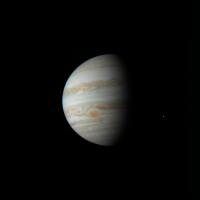
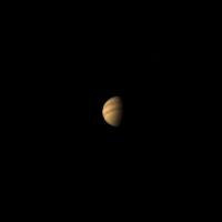
Single GRS frame from the approach movie.
|
|
|
|
|
|
|
Dec 1 2023, 08:47 PM
Post
#13
|
||
|
Member Group: Members Posts: 143 Joined: 22-July 14 Member No.: 7220 |
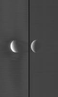
And all the RGB frames from the approach movie. The background noise really picks up on the last two or three frames:
|
|
|
|
|
|
|
Dec 2 2023, 02:39 AM
Post
#14
|
||
|
Senior Member Group: Members Posts: 2346 Joined: 7-December 12 Member No.: 6780 |
Some of my early thoughts about the striping artefacts below. Presumably not too much new insight thus far.
The superposed signal appears to be mostly low-frequency along x. There should be ways to filter out most of it. Here a very ad-hoc example of a cropped draft of JNCE_2023326_56C00140_V01 without and with some filtering along x:
It essentially removes wavelengths of more than ~100 pixels along x, kind of high-passing along x. I'm trying to learn more about the spectrum of the addiional signal. That may help to find a suitable filter. Some spectral features seem to be fairly constant after a first informal glance. A more formal analysis is work in progress. We'll see whether the properties of the stripes can be nailed down a little better. A high dark level may truncate the signal numerically during companding. That may limit the recovery of the original data. Combining/stacking multiple images over all three color channels may improve S/N. That's roughly the ideas I'm going to persue. |
|
|
|
|
|
|
Dec 2 2023, 06:12 AM
Post
#15
|
|
|
Senior Member Group: Members Posts: 2346 Joined: 7-December 12 Member No.: 6780 |
QUOTE (mcaplinger @ Dec 1 2023, 10:22 PM) ...We can change the temperature of the camera, but it's much easier to make it hotter than colder, and in general hotter is worse. There is plenty of literature that says that radiation damage of semiconductors can be annealed by heating in at least some cases. Two of several examples: G. Kim et al. "A study of radiation damage and heat annealing effect on the irradiated 3T active pixel sensor" QUOTE The most well-known effect of the x-ray CIS due to the radiation damage are increments in the reset voltage and dark current. These effects cause the quality of image to degrade. To overcome these problems, many sensor recovery methods are studied. Annealing is the best method among many other methods. For the assembled sensor, the heat annealing is most suitable. C. J. Marshall et al. "Hot Pixel Annealing Behavior in CCDs Irradiated at -83°C" QUOTE Hot pixel annealing began below -40 °C and the anneal process was largely completed by the time the detector reached +20°C. How well this applies to the JunoCam electronics is mostly outside of my access. All I can say is that the presumably radiation-induced reddening effect seems to have temporarily reversed a little bit after the chip was heated after, I think, PJ 49 or PJ50. For some reason I thought that this heating option for annealing was also considered for JunoCam by design. But I don't find the according reference any more. I'm aware of the experience that annealing will never be complete. I think that in doubt it's easier to cope with the thermal dark current than with severe radiation damage in case the heating is maintained during the flyby. If it's properly calibrated and reliable, the companding function could be offset by almost the level of the dark current. I know that we would see a lot more hot pixels. But that's something more or less systematic and reprodicible. |
|
|
|
|
Dec 2 2023, 03:17 PM
Post
#16
|
|
|
Senior Member Group: Members Posts: 2517 Joined: 13-September 05 Member No.: 497 |
QUOTE (Gerald @ Dec 1 2023, 10:12 PM) There is plenty of literature that says that radiation damage of semiconductors can be annealed by heating in at least some cases. The Junocam team is well aware of annealing. One might look carefully at the dark current in the past few marble movies for evidence of heating going back several orbits. (Dancing around the limits of what I can say here.) QUOTE I think that in doubt it's easier to cope with the thermal dark current than with severe radiation damage in case the heating is maintained during the flyby. If it's properly calibrated and reliable, the companding function could be offset by almost the level of the dark current. I know that we would see a lot more hot pixels. But that's something more or less systematic and reprodicible. As far as we can tell, this issue is not related to dark current, which is a more gaussian noise source. And there are some limits to the amount of offset that can be put into the standard companding function due to bit sizes of registers. The images are unusable with any degree of heating. If we could reduce the temperature below the level it's at with no heating, we would do that and we believe it would help, but that's not really possible (recall that Junocam is inside a thermal-blanketed volume with just the lens looking out, and by design it's a stable not-too-hot, not-too-cold temperature in there. There's no active cooling.) -------------------- Disclaimer: This post is based on public information only. Any opinions are my own.
|
|
|
|
|
Dec 3 2023, 01:01 AM
Post
#17
|
|
|
Senior Member Group: Members Posts: 1583 Joined: 14-October 05 From: Vermont Member No.: 530 |
Mostly in response to Gerald.
I'm afield of my field, which is digital CMOS-- and this isn't even CMOS, it's a CCD AFAICT, like your 2nd paper-- but I did seem to gather that this was a really bad transient that affected pretty much all pixels, like accumulating charge in the substrate... that VSUB net on the chip's datasheet? I say "like" that because I know nothing about how the chip functions, even after looking at the data sheet. I'm just too far out of understanding the charge accumulation/xfer stuff to speculate on where the charge accumulates when it gets zapped. I have some small and partial understanding of that in CMOS, but not even CMOS imaging chips. But the question I'm begging is... is this a presumed transient, so does hitting one of the various reset buttons in the system clear it, and what's the TAT? No answers required, just sharing my thoughts. Which are: I didn't jump to the conclusion that there's nonvolatile damage which must be annealed. I did jump to the conclusion that the (presumed) transient affected the whole system, not just some pixels. Could be wrong on all accounts. So from a system perspective, I thought, they'd be considering whether they can do curative cycles between imaging cycles. If there's time, and if it's worth the time. |
|
|
|
|
Dec 3 2023, 01:36 AM
Post
#18
|
|
|
Senior Member Group: Members Posts: 2517 Joined: 13-September 05 Member No.: 497 |
QUOTE (stevesliva @ Dec 2 2023, 05:01 PM) So from a system perspective, I thought, they'd be considering whether they can do curative cycles between imaging cycles. So you're suggesting, basically, that we turn it off and back on again? Always reasonable tech support advice. Unfortunately, whether that would help or not (and that's not clear), we can't do it for fear it will never start up again, as almost happened at PJ48. https://www.nasa.gov/missions/juno/nasas-ju...yby-of-jupiter/ If the images became completely unusable, we'll likely try this because there wouldn't be anything left to lose. [added: To be clear, we don't think this is a transient, but we can't rule it out and in the abstract your suggestion is perfectly reasonable.] -------------------- Disclaimer: This post is based on public information only. Any opinions are my own.
|
|
|
|
|
Dec 4 2023, 07:37 AM
Post
#19
|
||
|
Member Group: Members Posts: 408 Joined: 18-September 17 Member No.: 8250 |
Posted following at https://www.missionjuno.swri.edu/junocam/discussion
From the Image Processing Welcome message at https://www.missionjuno.swri.edu/junocam/processing#Welcome " JunoCam is now showing the effects of that radiation on some of its parts. PJ56 images show a reduction in our dynamic range and an increase in background and noise. We invite citizen scientists to explore new ways to process these images to continue to bring out the beauty and mysteries of Jupiter and its moons. " Being part of the JunoCam image processing community, gaining a clearer understanding of the challenges would enable us to enhance our image processing techniques. Transparently sharing technical details, insights, and ongoing analysis from the project would boost our efficiency and improve our ability to devise effective workarounds. The following image compares green channel PJ55_72 transformed with a very preliminary model of the image corruption issue with PJ56_191 raw data:
|
|
|
|
|
|
|
Dec 4 2023, 03:50 PM
Post
#20
|
|
|
Senior Member Group: Members Posts: 2517 Joined: 13-September 05 Member No.: 497 |
QUOTE (Brian Swift @ Dec 3 2023, 11:37 PM) Transparently sharing technical details, insights, and ongoing analysis from the project... Did you have specific questions? I can't really do anything with a request this broad. And I think you are overestimating the value of the "ongoing analysis". -------------------- Disclaimer: This post is based on public information only. Any opinions are my own.
|
|
|
|
|
Dec 4 2023, 08:42 PM
Post
#21
|
||
 IMG to PNG GOD Group: Moderator Posts: 2250 Joined: 19-February 04 From: Near fire and ice Member No.: 38 |
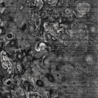
Destriping the images seems to be trivial. I've had fairly good success using code based on a description of what the ISIS3 dstripe application does but I haven't tried pystripe yet (mentioned in the first post of this thread). The resulting red and green images don't look too bad. If the situation doesn't get worse before or during PJ57 the Io images are going to be very interesting despite this problem. A very quick-and-dirty destriped version from image PJ56_132 (can be improved, in particular I'm treating this as a single image instead of treating each framelet as an individual image):
A question for Mike (if you cannot answer it I understand): Is it safe for me to assume that the images got corrupted before companding or is it possible that they got corrupted during/after companding? I'm pretty sure it was before companding, meaning that I should decompand the images before I destripe and subtract the background but I want to be sure. |
|
|
|
|
|
|
Dec 4 2023, 09:15 PM
Post
#22
|
||
|
Senior Member Group: Members Posts: 2517 Joined: 13-September 05 Member No.: 497 |
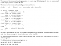
QUOTE (Bjorn Jonsson @ Dec 4 2023, 12:42 PM) Is it safe for me to assume that the images got corrupted before companding... Yes. Unfortunately one of the major impacts of the offset becoming so large is that low signals are normally quantized more finely than high signals, but with a large offset this doesn't happen, and this degrades the SNR of dark parts of the scene (and would do so even if the noise wasn't present at all.) In case it helps, the Junocam paper didn't provide as much information about the companding as it could have. This is all implicit in the lookup tables in the PDS product SIS, but just to be clear about how the hardware works, see below.
-------------------- Disclaimer: This post is based on public information only. Any opinions are my own.
|
|
|
|
|
|
|
Dec 5 2023, 03:29 AM
Post
#23
|
|
|
Member Group: Members Posts: 128 Joined: 10-December 06 From: Atlanta Member No.: 1472 |
Is there any possibility of changing the exposure time? I don't know if JunoCam can handle shorter exposures, but if it can and the exposure time is reduced 4x, it may improve the SNR by a factor of ~2. Unfortunately, it will also increase the file size by 4x, which may not be possible or practical.
|
|
|
|
|
Dec 5 2023, 03:38 AM
Post
#24
|
|
|
Senior Member Group: Members Posts: 2517 Joined: 13-September 05 Member No.: 497 |
QUOTE (siravan @ Dec 4 2023, 07:29 PM) Is there any possibility of changing the exposure time? I don't know if JunoCam can handle shorter exposures, but if it can and the exposure time is reduced 4x, it may improve the SNR by a factor of ~2. Unfortunately, it will also increase the file size by 4x, which may not be possible or practical. I'm not following why you think using a shorter exposure time would help, or why it would increase the file size. Junocam is a pushframe imager, so we could reduce the exposure time as much as we wanted below the nominal 1 IFOV of blur at 3.2 msec. As far as we can tell, the noise and offset is largely independent of exposure time. You can see this for yourself by comparing the RGB, methane, and single-band lightning search images. -------------------- Disclaimer: This post is based on public information only. Any opinions are my own.
|
|
|
|
|
Dec 5 2023, 04:47 AM
Post
#25
|
|
|
Member Group: Members Posts: 408 Joined: 18-September 17 Member No.: 8250 |
QUOTE (mcaplinger @ Dec 4 2023, 07:50 AM) Did you have specific questions? I can't really do anything with a request this broad. And I think you are overestimating the value of the "ongoing analysis". What causes have been considered/analyzed and dismissed? What are the current "most likely" causes? Is the problem before, in, or after the ADC? Is the companding implemented in HW circuit. And while we're at it, as-flown schematics of instrument. Particularly, path from CCD to RAM (assuming problem is known to occur before bytes reach RAM.) Is it just a coincidence that the noise (in de-companded values) is now ~256x larger (based on just looking at green channel from PJ55 and PJ56 "radiation trend monitoring" images.) |
|
|
|
|
Dec 5 2023, 05:16 AM
Post
#26
|
|
|
Senior Member Group: Members Posts: 2517 Joined: 13-September 05 Member No.: 497 |
QUOTE (Brian Swift @ Dec 4 2023, 08:47 PM) What causes have been considered/analyzed and dismissed? Bad bits out of ADC, basically everything after the CCD amplifier output. QUOTE What are the current "most likely" causes? Radiation degradation of the CCD or possibly a bias voltage supply. QUOTE Is the problem before, in, or after the ADC? Before. QUOTE Is the companding implemented in HW circuit. Digital hardware, see above. The problem is not in companding. QUOTE And while we're at it, as-flown schematics of instrument. I'm sure you're aware that this is not a very realistic request. There's a nice block diagram in https://www.missionjuno.swri.edu/pub/e/down...each_Camera.pdf that should answer many questions. As time has gone by, we've had to be more and more conservative about the level of detail we've released in the open literature due to ITAR. That said, it's more or less the same as what's described in a little more detail in https://agupubs.onlinelibrary.wiley.com/doi...29/2008JE003315 for the MRO MARCI, sections 3.3.3 to 3.3.5. I can't share the specific part numbers of any of the ICs, though. -------------------- Disclaimer: This post is based on public information only. Any opinions are my own.
|
|
|
|
|
Dec 5 2023, 07:10 AM
Post
#27
|
|
|
Member Group: Members Posts: 408 Joined: 18-September 17 Member No.: 8250 |
QUOTE (mcaplinger @ Dec 4 2023, 07:38 PM) I'm not following why you think using a shorter exposure time would help, or why it would increase the file size. Junocam is a pushframe imager, so we could reduce the exposure time as much as we wanted below the nominal 1 IFOV of blur at 3.2 msec. As far as we can tell, the noise and offset is largely independent of exposure time. You can see this for yourself by comparing the RGB, methane, and single-band lightning search images. I think they are suggesting taking 4 images, each with 1/4 exposure time and averaging/summing them together to beat down noise (which as I recall would run into limitations either on a buffer size or how fast data can be moved to RAM). QUOTE the noise and offset is largely independent of exposure time Since turning the instrument on and off ain't happening (for good reason). I was curious if there is any effect for either of: 1) taking several exposures as fast as possible (min exposure time, min INTERFRAME_DELAY) followed by a normal exposure. 2) taking a very long well-filling exposure, followed immediately by a normal exposure. Of course I don't know if the instrument is capable of either of these operations. ps. thanks for the responses to my questions. I am curious which specific ITAR sections are limiting you disclosure ability. |
|
|
|
|
Dec 5 2023, 03:19 PM
Post
#28
|
|
|
Senior Member Group: Members Posts: 2517 Joined: 13-September 05 Member No.: 497 |
QUOTE (Brian Swift @ Dec 4 2023, 11:10 PM) I think they are suggesting taking 4 images, each with 1/4 exposure time and averaging/summing them together to beat down noise It takes about 150 msec to read out a one-band image and about 255 msec for a three-band image, plus exposure time. So the typical visible exposure time of 3.2 or 6.4 msec is only a small fraction of that time. It might be barely possible to take one-band images at an interframe of say 160 msec, which would overlap downspin by more than 50%. That could help somewhat but it's a pretty big impact for not much return, it seems to me. 4X is just not possible. QUOTE 1) taking several exposures as fast as possible (min exposure time, min INTERFRAME_DELAY) followed by a normal exposure. 2) taking a very long well-filling exposure, followed immediately by a normal exposure. Both 1 and 2 would be limited in their cadence ("followed by/immediately" is no faster than the amount of time it takes to read the previous images out of DRAM to the s/c, many seconds). We've taken a range of exposure times (RGB/CH4/lightning) already and there seems to be very little difference in behavior with exposure time or from frame to frame at the standard interframe time. The fact that the offset occurs with images of black space suggests little dependence on signal level, we think it is a shift between the reset and video level coming out of the CCD. QUOTE I am curious which specific ITAR sections are limiting you disclosure ability. I'm not a lawyer, I just know what they tell me I can and can't say. Some of this is now covered by EAR rather than ITAR, but it's not clear that it's helped. Maybe https://www.space.commerce.gov/regulations/...ol-regulations/ would have some useful background. If you argued that this is being overapplied, I wouldn't disagree with you, but it's above my pay grade. -------------------- Disclaimer: This post is based on public information only. Any opinions are my own.
|
|
|
|
|
Dec 10 2023, 01:24 AM
Post
#29
|
||||||
|
IMG to PNG GOD Group: Moderator Posts: 2250 Joined: 19-February 04 From: Near fire and ice Member No.: 38 |
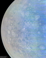
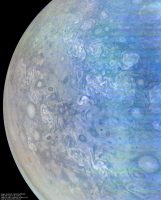
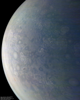
I have been making nice progress with the PJ56 images. This is image PJ56_140 at several different processing levels. The amount of processing increases from [a] to [d]. The images are illumination adjusted.
A short description of how the processing differs from [a] to [d]: [a] Destriped using code based on a description of what the ISIS3 dstripe application does. I experimented with several different destripe parameters. [b] Crude color correction in the purple areas. [c] Green and blue channels modified to reduce noise. Here the green channel is a combination of a low pass filtered green image and high pass filtered red image. The blue channel is a combination of a low pass filtered blue image and high pass filtered green image. [d] Enhanced contrast and color saturation. Keeping in mind what the original data looks like, I'm a bit surprised by the good quality of the red channel data here. However, the blue channel is almost useless in the darkest areas at right. And for completeness, a version that is supposed to be an approximately true color/contrast image. However, the color is preliminary and probably significantly less accurate than in images from earlier orbits.
|
|||||
|
|
|
|||||
|
Dec 15 2023, 11:45 PM
Post
#30
|
||
|
IMG to PNG GOD Group: Moderator Posts: 2250 Joined: 19-February 04 From: Near fire and ice Member No.: 38 |
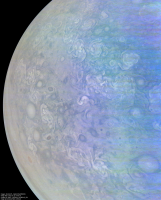
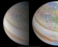
Image PJ56_132:
The left image is an approximately true color/contrast version and the one at right is illumination-adjusted and contrast enhanced. North is up. The red channel had some gaps that were filled using synthetic data created from the green channel. In addition, a narrow strip that contained only blue data was filled using data from image PJ56_135 (the quality of the PJ56_132 blue data was low so synthesizing acceptable red/green data from it was not possible). The resulting color composites have some spurious color variations that mainly manifest themselves as purplish or greenish areas. For obvious reasons, the color information is less reliable in the PJ56 images than in images from earlier perijoves, especially in dark areas. |
|
|
|
|
|
|
Dec 16 2023, 05:47 PM
Post
#31
|
|
|
Senior Member Group: Members Posts: 2517 Joined: 13-September 05 Member No.: 497 |
QUOTE (Bjorn Jonsson @ Dec 9 2023, 05:24 PM) I have been making nice progress with the PJ56 images. Thanks for doing this, Bjorn. Your results are impressive, and it makes me more optimistic that the PJ57 Io images will be useful. You're certainly right that the blue channel is most badly affected. -------------------- Disclaimer: This post is based on public information only. Any opinions are my own.
|
|
|
|
|
Dec 17 2023, 05:41 AM
Post
#32
|
|
|
Member Group: Members Posts: 233 Joined: 14-January 22 Member No.: 9140 |
Beautiful images, despite the upstream glitches. It feels dramatic to have the first closest Io flybys occur just as the radiation is starting to have this degree of impact. Fingers crossed!
|
|
|
|
|
Dec 17 2023, 05:22 PM
Post
#33
|
|
|
Member Group: Members Posts: 408 Joined: 18-September 17 Member No.: 8250 |
QUOTE (mcaplinger @ Dec 16 2023, 09:47 AM) You're certainly right that the blue channel is most badly affected. I wonder if there could be value in acquiring blue-only higher-TDI images. And also wonder, if red-green images were collected, could imaging cadence be increased to once per rotation (with the idea of having more images to average together to beat down random noise.) |
|
|
|
|
Dec 17 2023, 06:10 PM
Post
#34
|
|
|
Senior Member Group: Members Posts: 2517 Joined: 13-September 05 Member No.: 497 |
QUOTE (Brian Swift @ Dec 17 2023, 09:22 AM) I wonder if there could be value in acquiring blue-only higher-TDI images. If there was something important enough about the blue channel to make up for the costs of reduced imaging cadence, extra processing, etc, then sure. QUOTE And also wonder, if red-green images were collected, could imaging cadence be increased to once per rotation... No, not for any image larger than 20 or so frames. You have to acquire all of the frames into JDEA DRAM and then transfer them all to the spacecraft before starting the next image. (And I've just noticed an error in the Junocam paper -- it says "the data interface is a unidirectional three-signal RS-422 synchronous interface running at 20 Mbits/s" but the correct number is 4 Mbits/s.) -------------------- Disclaimer: This post is based on public information only. Any opinions are my own.
|
|
|
|
|
Dec 18 2023, 01:28 AM
Post
#35
|
|
|
IMG to PNG GOD Group: Moderator Posts: 2250 Joined: 19-February 04 From: Near fire and ice Member No.: 38 |
The PJ56 images are good enough that I wouldn't make any changes in an attempt to get better images at PJ57 unless there was no risk (or an extremely small risk). And an obvious problem is that the satellite flybys happen very quickly which limits things like extra blue images at longer exposures etc.
The most obvious change to me is to maybe use a different companding function (or modify the current function) in an attempt to increase the dynamic range in the dark areas, especially in the blue channel. I haven't tried applying such functions to test data but an important consideration is the quality of the red images. Improving the quality of the blue images with a different companding function might be a bad idea if it results in worse red images. The PJ56 red images are actually quite good and therefore more important than the blue images. Another idea is of course to completely omit the companding but that has a major drawback: Increased data storage requirements since the data would be 12 bits/pixel instead of 8. Data compression would probably also be less effective. |
|
|
|
|
Dec 18 2023, 02:32 AM
Post
#36
|
|
|
Senior Member Group: Members Posts: 2517 Joined: 13-September 05 Member No.: 497 |
QUOTE (Bjorn Jonsson @ Dec 17 2023, 05:28 PM) Another idea is of course to completely omit the companding... Alas, this isn't possible. The DRAM subsystem is designed around 8-bit pixels. In hindsight maybe we should have implemented a mode where one could get every other pixel in 12-bit form (there's something similar in CTX and LROC NAC) but obviously we weren't expecting this particular problem. Similarly, if there's a better companding function that would improve on the current one given all of the limitations on the hardware (described upthread), we haven't been able to come up with it. -------------------- Disclaimer: This post is based on public information only. Any opinions are my own.
|
|
|
|
|
Dec 18 2023, 04:47 AM
Post
#37
|
|
|
Member Group: Members Posts: 233 Joined: 14-January 22 Member No.: 9140 |
It's a somewhat unknowable unknown, but the information value of three color filters as opposed to two may in principle be either great or virtually zero or anywhere in-between for a given target. If the color slopes of every surface unit is smooth, then two filters gives you basically the same information as three. Io, however, is maybe not such a target, and even if we suspected it to be so in older imagery, Io might always have a chromatic surprise somewhere, at some spatial resolution, that we haven't yet seen. The imagery from other recent flybys could probably give us some great hints about this.
|
|
|
|
|
Dec 18 2023, 03:50 PM
Post
#38
|
|
|
Senior Member Group: Moderator Posts: 3233 Joined: 11-February 04 From: Tucson, AZ Member No.: 23 |
Yeah, Io's spectrum has a significant break around blue so it is hard to get blue data back from just green and red, like maybe you could do for Europa and Ganymede to an extent. Three colors is best but yeah, too bad there isn't a lot of time to do various tests on different settings to see if messing with the companding could yield improve dynamic range in the resulting 8-bit data, a bit like the LUT and ADC settings tests we've done in the past on HiRISE.
-------------------- &@^^!% Jim! I'm a geologist, not a physicist!
The Gish Bar Times - A Blog all about Jupiter's Moon Io |
|
|
|
|
Dec 18 2023, 06:11 PM
Post
#39
|
|
|
Member Group: Members Posts: 408 Joined: 18-September 17 Member No.: 8250 |
My current thought is that when taking images that are not "cadence constrained" (eg just Jupiter, not Io) would be to acquire "HDR" image sequences. Take a normal exposure image, followed as quickly as possible by a 3x or 4x longer exposure, and possibly followed by a 3rd even longer exposure. The idea being that the longer exposures will move the signal up out of the noise. And "exposure fusion" post processing could be used to recover useful imagery from the darker areas currently dominated by noise.
WRT companding. Probably want to eventually shift table (so bterm0 is about ~320 larger?), so lower ~100 companded values aren't going utilized. |
|
|
|
|
Dec 18 2023, 11:51 PM
Post
#40
|
|
|
Senior Member Group: Members Posts: 2517 Joined: 13-September 05 Member No.: 497 |
QUOTE (Brian Swift @ Dec 18 2023, 10:11 AM) WRT companding. Probably want to eventually shift table (so bterm0 is about ~320 larger?), so lower ~100 companded values aren't going utilized. The bterms are only 8 bits, unfortunately. We did not anticipate this particular problem. -------------------- Disclaimer: This post is based on public information only. Any opinions are my own.
|
|
|
|
|
Dec 19 2023, 02:54 AM
Post
#41
|
|
|
Member Group: Members Posts: 233 Joined: 14-January 22 Member No.: 9140 |
I just took Bjorn's approximately true color picture of Io from PJ 55, and tried synthesizing a blue channel from the green and red only. I subtracted half the red image from the green, then made that result about 1.5x brighter and used that as the blue. At a casual glance, this comes out looking almost indistinguishable from the original. So, unless the raw blue was used to help produce the green and/or red in that image, there's no doubt that we'll get something aesthetically great if we end up with only red and green data. But, it will be a fiction even if a pretty one and on the off-chance that there's actually an especially green or especially blue feature there (like a sulfur dioxide plume), it'll come out skewed.
I don't know what the chances are that the blue data would come back with some lines or pixels intact. As long as this image covers terrain seen from similar geometry in previous Juno imagery, there's the possibility of using that information to evaluate the veracity of such data in this imagery, and "ground truth" even the rare reliable blue pixel. There's potentially a detective story here to recover real color information at lower resolution. |
|
|
|
|
Dec 20 2023, 05:10 PM
Post
#42
|
||
|
Senior Member Group: Moderator Posts: 3233 Joined: 11-February 04 From: Tucson, AZ Member No.: 23 |
tried that out with one of the PJ55 images and it does some weird things to areas that are greenish, like Chors Patera.
This product does a nice job of point out areas of spectral variation between red and green, but in areas where there isn't much, like near the equator, it makes the resulting product grey.
-------------------- &@^^!% Jim! I'm a geologist, not a physicist!
The Gish Bar Times - A Blog all about Jupiter's Moon Io |
|
|
|
|
|
|
Dec 23 2023, 12:29 AM
Post
#43
|
||
|
IMG to PNG GOD Group: Moderator Posts: 2250 Joined: 19-February 04 From: Near fire and ice Member No.: 38 |
Creating synthetic images using a linear combination of two colors doesn't work as well for Io as it does for e.g. the other Galileans or even Jupiter. Using violet and green to create synthetic blue images works fairly well using something like B=G*w+V*(1-w) (and maybe also multiplying this with a value close to 1 but not exactly 1). However, something comparable doesn't work well if you want synthetic red from IR756 and green Galileo images. I experimented with this years ago when I wanted a closer to true color version of the Galileo C21 global mosaic of Io. I ended up using a non-linear combination of IR756 and green with great results. This had one major drawback though: It worked well only for Io's anti-Jupiter's hemisphere. For the subjovian hemisphere a different formula was needed.
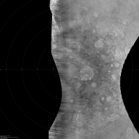
And now something different, a north polar map of Jupiter created from a mosaic of the PJ56_145 and PJ56_147 images. This is from the red channel only. The contrast has been increased.
|
|
|
|
|
|
 |

|
Lo-Fi Version | Time is now: 16th May 2024 - 12:46 AM |
|
RULES AND GUIDELINES Please read the Forum Rules and Guidelines before posting. IMAGE COPYRIGHT |
OPINIONS AND MODERATION Opinions expressed on UnmannedSpaceflight.com are those of the individual posters and do not necessarily reflect the opinions of UnmannedSpaceflight.com or The Planetary Society. The all-volunteer UnmannedSpaceflight.com moderation team is wholly independent of The Planetary Society. The Planetary Society has no influence over decisions made by the UnmannedSpaceflight.com moderators. |
SUPPORT THE FORUM Unmannedspaceflight.com is funded by the Planetary Society. Please consider supporting our work and many other projects by donating to the Society or becoming a member. |
|