Rev 126 - Feb 4-22, 2010 - Mimas (main target), Tethys, Iapetus, Calypso and mutual events too |

 Unmanned Spaceflight.com > Outer Solar System > Saturn > Cassini Huygens > Cassini's ongoing mission and raw images
  |
Rev 126 - Feb 4-22, 2010 - Mimas (main target), Tethys, Iapetus, Calypso and mutual events too |
 Jan 25 2011, 08:22 PM Jan 25 2011, 08:22 PM
Post
#136
|
||||||||
 IMG to PNG GOD  Group: Moderator Posts: 2251 Joined: 19-February 04 From: Near fire and ice Member No.: 38 |
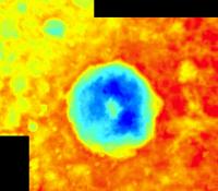
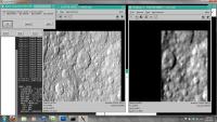
The data discussed earlier in this thread was released at the PDS Imaging Node early this month. Using this data I have now created a far more accurate DEM of Herschel than the one I mentioned earlier in the thread. The DEM is based on stereo imagery.
First a section of the DEM. It is fairly detailed but not flawless. It is slightly 'tilted', resulting in higher elevations east of Herschel than west. The DEM reveals that Herschel has a raised rim and the crater floor is deepest north and southeast of the central peak. Now I really need to find the time to learn how to correct the camera angles using ISIS (any tips?  ), the result should be a significant improvement in accuracy. ), the result should be a significant improvement in accuracy.
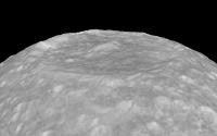
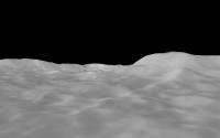
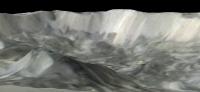
Then some quick and dirty test renders where data from a simple cylindrical map has been draped over the DEM. This map is a byproduct of the DEM creation process (it really is an orthophoto). First an overview of Herschel. The crater floor is obviously fairly flat and not curved:
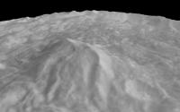
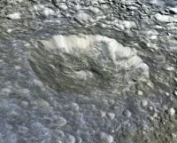
An overview of the central peak:
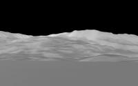
The view from the central peak summit looking east:
Looking northeast from a few km above the crater floor, the central peak is visible at right:
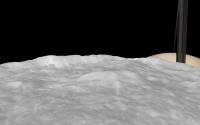
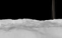
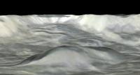
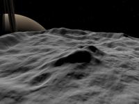
The field of view (FOV) in all of these images is 45° except for the last one where it is 50°. They are rendered using true vertical relief in all cases. I then decided to add Saturn just to see what things look like. Two quick test renders with a 50° FOV. First one looking east from above the western rim:
And looking east over the central peak:
|
|||||||
 |
 
|
|||||||
|
Jan 25 2011, 08:44 PM
Post
#137
|
|
 Senior Member Group: Moderator Posts: 3233 Joined: 11-February 04 From: Tucson, AZ Member No.: 23 |
Which version of ISIS are you running? I use ISIS2 and use deltack to fix ISS camera angles. If you use ISIS3... well, umm, there is a reason I still use ISIS2...
-------------------- &@^^!% Jim! I'm a geologist, not a physicist!
The Gish Bar Times - A Blog all about Jupiter's Moon Io |
|
|
|
|
Jan 25 2011, 10:07 PM
Post
#138
|
|
|
IMG to PNG GOD Group: Moderator Posts: 2251 Joined: 19-February 04 From: Near fire and ice Member No.: 38 |
I haven't been using ISIS a lot (I generated the DEM using software written by myself) but I have used both ISIS2 and ISIS3 a bit - I have both versions on my machine.
|
|
|
|
|
Jan 25 2011, 11:12 PM
Post
#139
|
|||
|
Senior Member Group: Moderator Posts: 3233 Joined: 11-February 04 From: Tucson, AZ Member No.: 23 |
Well, I know with ISIS2, you can use deltack to adjust the camera angles by comparing the images to a synthetic image, a basemap, or a previously corrected image, for example. Below are so
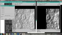
If you want to tie the image to a synthetic image (good for full-disk image where you are basically doing an interactive limbfit): CODE levgeoplane from=W1673418018_1.trim2.cub to=W1673418018_1.ema2.cub lat=no lon=no ema=yes deltack from=W1673418018_1.trim2.cub iline=517 isamp=390 tline=516 tsamp=391 + ck1to=/data/cassini/perry/Rev143/Rev143.bc If you want to tie the image to a basemap or previously reprojected image (if you are making a quick mosaic or you are tying color filter image from a single frame): CODE lev2tolev1 from=../../W1673418018_1.orth.cub from2=N1673418904_1.trim2.cub + tfile=N1673418904_1.ctrl.dat geom from=../../W1673418018_1.orth.cub to=N1673418904_1.ctrl.cub tfile=N1673418904_1.ctrl.dat deltack from=N1673418904_1.trim2.cub iline=505 isamp=598 tline=497 tsamp=615 + ck1to=/data/cassini/perry/Rev143/Rev143.bc To get the number for deltack, you use qview. You first load the image you want to adjust, then the control image (either the synthetic image or the control image from the basemap/other image). Make sure the two images use the same magnification and Link the two images. Also click the check mark next to Register and type in a file name (in the example below, I used ctrl)
Then you blink the two images using the Blink dialog box. You can move the control image around using the move tool (second button from the left). Clicking using the left mouse button at the top of that image will move it down one pixel (multipled by the scale of the image, in this case, 2 pixels), clicking the bottom of the image will move it up 1, clicking the left side will move it to the right by one pixel, click the right side will move it to the left. Clicking in the corners also works, for example clicking in the upper left corner will move the control image down and to the right. You keep shifting the control image around until the two images, blinking in the other window, are lined up as best as you can make it. Once you have that, you move your mouse cursor over to the original image and you press Ctrl+S. This will bring up the Control Point save dialog box.
The numbers in this box are what you put into deltack. In my example, the first number, 458, goes with tline. The second number, 460, goes with tsamp. The third number, 466, goes with iline. Finally, the fourth number, 451, goes with isamp. Click OK then you can run deltack using the command line. I do this so often, I can honestly do this in my sleep, but that means that it might be difficult for me to clearly explain this to others. If you have any questions, use "help deltack" in TAE for a more detailed explanation and other usage cases. -------------------- &@^^!% Jim! I'm a geologist, not a physicist!
The Gish Bar Times - A Blog all about Jupiter's Moon Io |
||
|
|
|
||
|
Jan 26 2011, 12:34 AM
Post
#140
|
||||
 Member Group: Members Posts: 207 Joined: 6-March 07 From: houston, texas Member No.: 1828 |
Good work there on Herschel.
See also my posting about high-resolution Herschel topography http://stereomoons.blogspot.com/. Here I do have rectified and registered imagery tied to my global control network. The global DEM is also tied to does indeed show that the floor is deeper to the east and there is an ejecta blanket, among other things. These were described in my LSPC abstract and will be shown there in March. Ive also added the full-res color maps, which are subtle in this rendering. Now all i need is a tool to render the view on a spherical instead of an infinitely "flat" surface. What do you use? paul
Attached thumbnail(s)
-------------------- Dr. Paul Schenk, Lunar and Planetary Institute, Houston TX
http://stereomoons.blogspot.com; http://www.youtube.com/galsat400; http://www.lpi.usra.edu/science/schenk/ |
|||
|
|
|
|||
|
Mar 14 2011, 03:18 PM
Post
#141
|
|
|
Member Group: Members Posts: 207 Joined: 6-March 07 From: houston, texas Member No.: 1828 |
Just posted my Mimas Herschel video to Youtube!
-------------------- Dr. Paul Schenk, Lunar and Planetary Institute, Houston TX
http://stereomoons.blogspot.com; http://www.youtube.com/galsat400; http://www.lpi.usra.edu/science/schenk/ |
|
|
|
|
Jun 4 2011, 12:54 AM
Post
#142
|
|
|
IMG to PNG GOD Group: Moderator Posts: 2251 Joined: 19-February 04 From: Near fire and ice Member No.: 38 |
I'm resurrecting this discussion because now I'm again working on DEMs of Mimas and Enceladus. Also I had some problems with ISIS earlier where not everything was working properly (in particular qview didn't work) but now everything seems to work perfectly and I have dozens of images where I want to fix the camera pointing.
QUOTE (volcanopele @ Jan 25 2011, 11:12 PM)  Well, I know with ISIS2, you can use deltack to adjust the camera angles by comparing the images to a synthetic image, a basemap, or a previously corrected image, for example. Below are so Have you been using deltack only or have you used jigsaw as well? I get the impression that when I want to mosaic lots of images into an (eventual) map I should probably be using jigsaw but I may be wrong. QUOTE (volcanopele @ Jan 25 2011, 11:12 PM) If you want to tie the image to a basemap or previously reprojected image (if you are making a quick mosaic or you are tying color filter image from a single frame): CODE lev2tolev1 from=../../W1673418018_1.orth.cub from2=N1673418904_1.trim2.cub + tfile=N1673418904_1.ctrl.dat geom from=../../W1673418018_1.orth.cub to=N1673418904_1.ctrl.cub tfile=N1673418904_1.ctrl.dat deltack from=N1673418904_1.trim2.cub iline=505 isamp=598 tline=497 tsamp=615 + ck1to=/data/cassini/perry/Rev143/Rev143.bc When you say "basemap or previously reprojected image" do you mean something like for example this? One reason I ask is that despite the fact that this map is big (14400x7200 pixels) the resolution is remarkably low in my opinion and and there are some black areas (possibly due to a contrast stretch or filtering). This makes accurate measurements difficult in some areas when dealing with hi-res images I want to correct. |
|
|
|
|
Aug 28 2011, 11:47 PM
Post
#143
|
||
|
IMG to PNG GOD Group: Moderator Posts: 2251 Joined: 19-February 04 From: Near fire and ice Member No.: 38 |
This is an experimental Herschel animation:
http://www.youtube.com/watch?v=sfCQ7f7PMbc
The DEM is an improved version of my DEM mentioned earlier in the thread. I used ISIS to improve the camera angles and instead of only using a DEM derived from stereo imagery I increased the DEM's resolution by combining two DEMs. One created using stereo imagery (for large scale features) and another one created using shape from shading (SFS; for small scale features). When using SFS care must be taken as it cannot distinguish between intensity variations caused by topography and variations caused by albedo differences. I think the SFS DEM I used is fairly accurate - after comparing the stereo DEM and some Cassini images it seems to me that most of the brightness variations on Herschel's floor are caused by topography. The final step was to 'cheat' a bit by adding lots of fictional, small craters because at this close range the surface looked too smooth without them. The field of view is 50 degrees and the distance from Mimas' center is constant (228 km) throughout the animation. When rendering this I used a uniformly white texture map, i.e. all of the surface details are coming from the DEM. |
|
|
|
|
|
|
Aug 29 2011, 10:21 PM
Post
#144
|
|
|
Member Group: Members Posts: 121 Joined: 26-June 04 From: Austria Member No.: 89 |
Björn, excellent animation !
...I think that the rings of Saturn must be edge on from Mimas, isn it ? Robert PS: according Wikipedia Mimas´ inclination is 1.574° |
|
|
|
|
Aug 29 2011, 10:23 PM
Post
#145
|
|
 Senior Member Group: Members Posts: 1431 Joined: 26-July 08 Member No.: 4270 |
Mimas has a slightly inclined orbit IIRC.
-------------------- -- Hungry4info (Sirius_Alpha)
|
|
|
|
|
Sep 1 2011, 09:49 PM
Post
#146
|
|
 Member Group: Members Posts: 796 Joined: 27-February 08 From: Heart of Europe Member No.: 4057 |
It looks like movie from Kaguya's HD camera, excellent!
-------------------- |
|
|
|
|
Sep 1 2011, 11:26 PM
Post
#147
|
|
|
Solar System Cartographer Group: Members Posts: 10171 Joined: 5-April 05 From: Canada Member No.: 227 |
Great job! And while looking at it I saw your Amalthea flyby as well - that's great too. I seem to recognize that shape!
Phil -------------------- ... because the Solar System ain't gonna map itself.
Also to be found posting similar content on https://mastodon.social/@PhilStooke Maps for download (free PD: https://upload.wikimedia.org/wikipedia/comm...Cartography.pdf NOTE: everything created by me which I post on UMSF is considered to be in the public domain (NOT CC, public domain) |
|
|
|
|
Sep 2 2011, 03:23 PM
Post
#148
|
|
|
IMG to PNG GOD Group: Moderator Posts: 2251 Joined: 19-February 04 From: Near fire and ice Member No.: 38 |
This is not unexpected as I used your shape model as a starting point for my Amalthea 3D model. Rather strangely (at least in my opinion) no post-Galileo shape models of Jupiter's small satellites seem to be available (or at least I haven't found any).
However, I just 'discovered' something interesting, a fairly recent shape model of Mimas that I need to take a look at: http://sbn.psi.edu/pds/resource/mimasshape.html |
|
|
|
|
Sep 2 2011, 03:45 PM
Post
#149
|
|
|
Solar System Cartographer Group: Members Posts: 10171 Joined: 5-April 05 From: Canada Member No.: 227 |
It may be that the small Jovian satellites were lower priority than all the exciting things we've had since then. Only Thebe would be a good candidate for modelling anyway. I did a rough shape model of Thebe but never refined it very much.
Phil -------------------- ... because the Solar System ain't gonna map itself.
Also to be found posting similar content on https://mastodon.social/@PhilStooke Maps for download (free PD: https://upload.wikimedia.org/wikipedia/comm...Cartography.pdf NOTE: everything created by me which I post on UMSF is considered to be in the public domain (NOT CC, public domain) |
|
|
|
|
Sep 2 2011, 07:16 PM
Post
#150
|
|
 Member Group: Members Posts: 700 Joined: 3-December 04 From: Boulder, Colorado, USA Member No.: 117 |
Beautiful, Bjorn!
It immediately reminded me of the opening of Jim Blinn's Voyager 2 animation, done back in 1980 with a completely invented DEM. It's remarkable what he was able to do back then... John |
|
|
|
|

|
Lo-Fi Version | Time is now: 29th May 2024 - 02:52 AM |
|
RULES AND GUIDELINES Please read the Forum Rules and Guidelines before posting. IMAGE COPYRIGHT |
OPINIONS AND MODERATION Opinions expressed on UnmannedSpaceflight.com are those of the individual posters and do not necessarily reflect the opinions of UnmannedSpaceflight.com or The Planetary Society. The all-volunteer UnmannedSpaceflight.com moderation team is wholly independent of The Planetary Society. The Planetary Society has no influence over decisions made by the UnmannedSpaceflight.com moderators. |
SUPPORT THE FORUM Unmannedspaceflight.com is funded by the Planetary Society. Please consider supporting our work and many other projects by donating to the Society or becoming a member. |
|