Rover Orientation Data, Where can one find detailed rover orientation data? |

Rover Orientation Data, Where can one find detailed rover orientation data? |
 May 28 2011, 04:20 AM May 28 2011, 04:20 AM
Post
#1
|
|
 Senior Member  Group: Members Posts: 2228 Joined: 1-December 04 From: Marble Falls, Texas, USA Member No.: 116 |
I am trying to quantify Spirit's final resting orientation, but I would generally like to learn how to determine the orientation of either rover for any particular sol. I'm sure this data is in the MMB files somewhere, but I haven't been able to identify it. Likewise, I am sure it is somewhere in the Analyst's Notebook database and/or the Pancam data tracking database, but again, I can't find it.
Spirit's final orientation is the main thing I am looking for, but any orientation assistance would be greatly appreciated. Thanks. -------------------- ...Tom
I'm not a Space Fan, I'm a Space Exploration Enthusiast. |
 |
 
|
 |
|
May 28 2011, 04:27 AM
Post
#2
|
|
|
Founder Group: Chairman Posts: 14432 Joined: 8-February 04 Member No.: 1 |
The PDS label label for just about every image, I think, includes a lot of orientation data. It's huge - but here's a segment of it
CODE ...... ROVER_MOTION_COUNTER = (138, 1230, 11, 148, 221) ROVER_MOTION_COUNTER_NAME = (SITE, DRIVE, IDD, PMA, HGA) ..... /* COORDINATE SYSTEM STATE: ROVER */ GROUP = ROVER_COORDINATE_SYSTEM COORDINATE_SYSTEM_INDEX = (138, 1230, 11, 148, 221) COORDINATE_SYSTEM_INDEX_NAME = (SITE, DRIVE, IDD, PMA, HGA) COORDINATE_SYSTEM_NAME = ROVER_FRAME ORIGIN_OFFSET_VECTOR = (-0.227241, 0.177903, 0.0358358) ORIGIN_ROTATION_QUATERNION = (0.885949, -0.169903, 0.00321267, -0.431529) POSITIVE_AZIMUTH_DIRECTION = CLOCKWISE POSITIVE_ELEVATION_DIRECTION = UP QUATERNION_MEASUREMENT_METHOD = COARSE REFERENCE_COORD_SYSTEM_INDEX = 138 REFERENCE_COORD_SYSTEM_NAME = SITE_FRAME END_GROUP = ROVER_COORDINATE_SYSTEM /* COORDINATE SYSTEM STATE: INSTRUMENT DEPLOYMENT DEVICE */ GROUP = IDD_COORDINATE_SYSTEM COORDINATE_SYSTEM_INDEX = (138, 1230, 11, 148, 221) COORDINATE_SYSTEM_INDEX_NAME = (SITE, DRIVE, IDD, PMA, HGA) COORDINATE_SYSTEM_NAME = MI_FRAME ORIGIN_OFFSET_VECTOR = (0.998908, -0.112816, -0.124504) ORIGIN_ROTATION_QUATERNION = (0.559273, -0.497552, -0.443273, 0.493117) POSITIVE_AZIMUTH_DIRECTION = CLOCKWISE POSITIVE_ELEVATION_DIRECTION = DOWN REFERENCE_COORD_SYSTEM_INDEX = (138, 1230, 11, 148, 221) REFERENCE_COORD_SYSTEM_NAME = ROVER_FRAME END_GROUP = IDD_COORDINATE_SYSTEM /* ARTICULATION DEVICE STATE: PANCAM MAST ASSEMBLY */ GROUP = PMA_ARTICULATION_STATE ARTICULATION_DEVICE_ID = "PMA" ARTICULATION_DEVICE_NAME = "PANCAM MAST ASSEMBLY" ARTICULATION_DEVICE_ANGLE = (0.553583 <rad>, 0.69753 <rad>, 0.553568 <rad>, 0.69766 <rad>, 1.21798 <rad>, -0.296728 <rad>) ARTICULATION_DEVICE_ANGLE_NAME = ("AZIMUTH-MEASURED", "ELEVATION-MEASURED", "AZIMUTH-REQUESTED", "ELEVATION-REQUESTED", "AZIMUTH-INITIAL", "ELEVATION-INITIAL") ARTICULATION_DEVICE_MODE = DEPLOYED END_GROUP = PMA_ARTICULATION_STATE /* ARTICULATION DEVICE STATE: HIGH GAIN ANTENNA */ GROUP = HGA_ARTICULATION_STATE ARTICULATION_DEVICE_ID = "HGA" ARTICULATION_DEVICE_NAME = "HIGH GAIN ANTENNA" ARTICULATION_DEVICE_ANGLE = (2.88001 <rad>, 0.0198442 <rad>) ARTICULATION_DEVICE_ANGLE_NAME = (AZIMUTH, ELEVATION) END_GROUP = HGA_ARTICULATION_STATE /* ARTICULATION DEVICE STATE: FILTER */ GROUP = FILTER_ARTICULATION_STATE ARTICULATION_DEVICE_ID = "FILTER" ARTICULATION_DEVICE_NAME = "FILTER ACTUATORS" ARTICULATION_DEV_POSITION = (8, 8, 1) ARTICULATION_DEV_POSITION_ID = ("PANCAM_L8_440NM_SOL_ND5", "PANCAM_R8_880NM_SOL_ND5", "MI_CLOSED") ARTICULATION_DEV_POSITION_NAME = ("LEFT PANCAM FILTER", "RIGHT PANCAM FILTER", "MI DUST COVER") END_GROUP = FILTER_ARTICULATION_STATE /* ARTICULATION DEVICE STATE: INSTRUMENT DEPLOYMENT DEVICE */ GROUP = IDD_ARTICULATION_STATE ARTICULATION_DEVICE_ID = "IDD" ARTICULATION_DEVICE_NAME = "INSTRUMENT DEPLOYMENT DEVICE" ARTICULATION_DEVICE_ANGLE = (-0.118184 <rad>, -0.899982 <rad>, 1.53029 <rad>, 2.38935 <rad>, 1.5708 <rad>, -0.126481 <rad>, -0.903681 <rad>, 1.53503 <rad>, 2.38834 <rad>, 1.516 <rad>) ARTICULATION_DEVICE_ANGLE_NAME = ("JOINT 1 AZIMUTH-ENCODER", "JOINT 2 ELEVATION-ENCODER", "JOINT 3 ELBOW-ENCODER", "JOINT 4 WRIST-ENCODER", "JOINT 5 TURRET-ENCODER", "JOINT 1 AZIMUTH-POTENTIOMETER", "JOINT 2 ELEVATION-POTENTIOMETER", "JOINT 3 ELBOW-POTENTIOMETER", "JOINT 4 WRIST-POTENTIOMETER", "JOINT 5 TURRET-POTENTIOMETER") ARTICULATION_DEVICE_MODE = "FREE SPACE" ARTICULATION_DEVICE_TEMP = (-23.8068 <degC>, -14.6212 <degC>) ARTICULATION_DEVICE_TEMP_NAME = ("AZIMUTH JOINT 1", "TURRET JOINT 5") ARTICULATION_DEV_VECTOR = (0.140944, -0.303824, 0.942245) ARTICULATION_DEV_INSTRUMENT_ID = "MI" ARTICULATION_DEV_VECTOR_NAME = GRAVITY CONTACT_SENSOR_STATE = ("NO CONTACT", "NO CONTACT", CONTACT, CONTACT, "NO CONTACT", "NO CONTACT", OPEN, "NO CONTACT") CONTACT_SENSOR_STATE_NAME = ("MI SWITCH 1", "MI SWITCH 2", "RAT SWITCH 1", "RAT SWITCH 2", "MB SWITCH 1", "MB SWITCH 2", "APXS DOOR SWITCH", "APXS CONTACT SWITCH") END_GROUP = IDD_ARTICULATION_STATE /* COORDINATE SYSTEM STATE: PANCAM MAST ASSEMBLY */ GROUP = PMA_COORDINATE_SYSTEM COORDINATE_SYSTEM_INDEX = (138, 1230, 11, 148, 221) COORDINATE_SYSTEM_INDEX_NAME = (SITE, DRIVE, IDD, PMA, HGA) COORDINATE_SYSTEM_NAME = MAST_FRAME ORIGIN_OFFSET_VECTOR = (0.45781, 0.02779, -1.09668) ORIGIN_ROTATION_QUATERNION = (0.894388, -0.100912, 0.35272, 0.255881) POSITIVE_AZIMUTH_DIRECTION = CLOCKWISE POSITIVE_ELEVATION_DIRECTION = UP REFERENCE_COORD_SYSTEM_INDEX = (138, 1230, 11, 148, 221) REFERENCE_COORD_SYSTEM_NAME = ROVER_FRAME END_GROUP = PMA_COORDINATE_SYSTEM /* ARTICULATION DEVICE STATE: MOBILITY CHASSIS */ GROUP = CHASSIS_ARTICULATION_STATE ARTICULATION_DEVICE_ID = "CHASSIS" ARTICULATION_DEVICE_NAME = "MOBILITY CHASSIS" ARTICULATION_DEVICE_ANGLE = (-0.0120352 <rad>, 0.00844853 <rad>, -0.0256182 <rad>, -0.0516135 <rad>, -0.382922 <rad>, -0.459977 <rad>, 0.158197 <rad>) ARTICULATION_DEVICE_ANGLE_NAME = ("LEFT FRONT WHEEL POTENTIOMETER", "RIGHT FRONT WHEEL POTENTIOMETER", "LEFT REAR WHEEL POTENTIOMETER", "RIGHT REAR WHEEL POTENTIOMETER", "LEFT BOGIE POTENTIOMETER", "RIGHT BOGIE POTENTIOMETER", "DIFFERENTIAL BOGIE POTENTIOMETER") ARTICULATION_DEVICE_MODE = DEPLOYED END_GROUP = CHASSIS_ARTICULATION_STATE .... /* DERIVED GEOMETRY DATA ELEMENTS: ROVER FRAME */ GROUP = ROVER_DERIVED_GEOMETRY_PARMS INSTRUMENT_AZIMUTH = 31.9313 <deg> INSTRUMENT_ELEVATION = 43.0455 <deg> REFERENCE_COORD_SYSTEM_INDEX = (138, 1230, 11, 148, 221) REFERENCE_COORD_SYSTEM_NAME = ROVER_FRAME END_GROUP = ROVER_DERIVED_GEOMETRY_PARMS /* DERIVED GEOMETRY DATA ELEMENTS: SITE FRAME */ GROUP = SITE_DERIVED_GEOMETRY_PARMS INSTRUMENT_AZIMUTH = -38.2947 <deg> INSTRUMENT_ELEVATION = 42.3127 <deg> REFERENCE_COORD_SYSTEM_INDEX = 138 REFERENCE_COORD_SYSTEM_NAME = SITE_FRAME SOLAR_AZIMUTH = 326.775 <deg> SOLAR_ELEVATION = 45.0107 <deg> END_GROUP = SITE_DERIVED_GEOMETRY_PARMS That basically includes the complete 'state' of the vehicle. IDD, PMA, Wheels, Chassis, suspension...everything. |
|
|
|
|
May 28 2011, 04:59 PM
Post
#3
|
|
|
Senior Member Group: Members Posts: 2228 Joined: 1-December 04 From: Marble Falls, Texas, USA Member No.: 116 |
Thanks, Doug. I wasn't aware of the label data. If I am understanding this data correctly, it appears that I will need to learn the mathematics of quaternions in order to make any sense of it. I wonder if there is any other source of data where the quaternions have been converted into something more intelligible to me.
-------------------- ...Tom
I'm not a Space Fan, I'm a Space Exploration Enthusiast. |
|
|
|
|
May 29 2011, 06:28 AM
Post
#4
|
|
|
Senior Member Group: Members Posts: 2228 Joined: 1-December 04 From: Marble Falls, Texas, USA Member No.: 116 |
I'm just following up on my own question. I found a quaternion calculator on line that supposedly could convert a quaternion into a set of angles in degrees. Using the rover quaternion from Doug's example above, it returned the following results.
CODE heading -12.658311877406014 degrees attitude -49.970826789740684 degrees bank -27.62979515200747 degrees Heading, attitude, and bank are apparently the equivalent of the aeronautical terms: yaw, pitch, and roll. A heading of about -12.7 degrees is slightly west of north, which seems reasonable. The attitude and bank angles are way too large to be reasonable for Spirit's orientation. I guess I have more work to do. -------------------- ...Tom
I'm not a Space Fan, I'm a Space Exploration Enthusiast. |
|
|
|
|
May 29 2011, 07:35 AM
Post
#5
|
|
|
Merciless Robot Group: Admin Posts: 8783 Joined: 8-December 05 From: Los Angeles Member No.: 602 |
Tom, I don't know if I'd discard the attitude & bank data just yet. For one thing, what is the reference for those numbers: local vertical or the martian geoid? Given that the source is probably the IMU, I'd bet on the latter. Also, recall that Spirit was already sideways (R side high) on the slope of Home Plate.
IMO, I don't find those numbers necessarily unreasonable. She was in a precarious situation. -------------------- A few will take this knowledge and use this power of a dream realized as a force for change, an impetus for further discovery to make less ancient dreams real.
|
|
|
|
|
May 30 2011, 05:43 AM
Post
#6
|
|
|
Senior Member Group: Members Posts: 2228 Joined: 1-December 04 From: Marble Falls, Texas, USA Member No.: 116 |
Thanks for the support, Nick. I haven't given up on them yet, but I am still confused. The converted angles don't seem to jive with the rover model displayed by MMB for the same location. I appreciate what you are saying, and you are probably right in questioning the reference. I'm trying to check that out. It also occurred to me that the reference could be a previous position.
I have no real experience with IMUs. There wouldn't be much difference between local vertical and a normal to the geoid, would there? -------------------- ...Tom
I'm not a Space Fan, I'm a Space Exploration Enthusiast. |
|
|
|
|
May 30 2011, 10:35 AM
Post
#7
|
|
 Member Group: Members Posts: 593 Joined: 20-April 05 Member No.: 279 |
QUOTE (CosmicRocker @ May 28 2011, 05:59 PM)  ...it appears that I will need to learn the mathematics of quaternions in order to make any sense of it. My maths - a dodgy A-level gained three decades ago - was required to use quaternions about a year ago on a 3d modelling issue in Flash. I "got it" after some struggling, wrote the code and it all worked well. A week later, the code still made some sense to me. When I came back to change some things a fortnight after that, I found it had become utterly unintelligible. Quaternions, I think, mark my limit! Tough to gain, very easy to lose. Andy |
|
|
|
|
May 30 2011, 01:06 PM
Post
#8
|
|
|
Merciless Robot Group: Admin Posts: 8783 Joined: 8-December 05 From: Los Angeles Member No.: 602 |
Tom, my experience with inertial nav systems is almost entirely aircraft-related, so within that context the difference between local vertical & the geoid is significant enough to be considered, esp. during initial system alignment on Earth. (Choice of the reference geoid is also important; there are several in current use.) I don't know how refined such data is for Mars yet.
As you pointed out, though that might not matter for the MER INS. All that stuff matters for initial platform alignment on a planetary surface, which works basically like this for aircraft inertial systems: 1. Platform levels out orthogonal to local vertical. 2. Amount & direction of correction required to keep platform level over time (normally, a few minutes) is measured. 3. Correction rate is matched to expected drift rate to find latitude; correction direction used to find north. (Finding exact longitude is usually done by entering an appoximate longitude during the alignment process, which is subsequently refined by the system; there's no real easy way for the system to sense that independently.) I suspect that the MERs haven't been going through full daily alignments for all this time; after morning wake-up, they might well just spin up to the last stored coordinates. Over time, this will drift (normally at a fixed rate) due to inherent & unavoidable minor mechanical imperfections in the system. Therefore, I wonder if this raw data you're working with might have substantial cumulative errors included that are subtracted during groundside processing @ JPL. Anyhow. Sorry for the long stream-of-consciousness post; was trying to think this through.  Good luck! Good luck!
-------------------- A few will take this knowledge and use this power of a dream realized as a force for change, an impetus for further discovery to make less ancient dreams real.
|
|
|
|
|
May 30 2011, 01:13 PM
Post
#9
|
|
 Senior Member Group: Moderator Posts: 2262 Joined: 9-February 04 From: Melbourne - Oz Member No.: 16 |
Tom, I played around with rover quaternions years ago, I was never totally convinced I had got it working exactly right but comparing my code with the maths on calculator you posted I think you need to swap the last two elements over. Then you get numbers close to what I get from code I've used in the past to automatically generate panoramas with flat horizons.
heading -50.58337307972186 degrees attitude 8.761900410435159 degrees bank -17.565753444479686 degrees I'm not sure what the -50 for heading refers to as Spirt was facing very close to north, I have only every been interested in the pitch (attitude) and roll (bank) numbers which are about right I think. -------------------- |
|
|
|
|
May 30 2011, 04:38 PM
Post
#10
|
|
|
Merciless Robot Group: Admin Posts: 8783 Joined: 8-December 05 From: Los Angeles Member No.: 602 |
James, all I can think is that the heading figure may be expressed in relative terms; maybe -50 deg off of the rover's longitudinal axis at platform alignment? Again, it's extremely important to understand the reference axes & error correction set to interpret this data.
-------------------- A few will take this knowledge and use this power of a dream realized as a force for change, an impetus for further discovery to make less ancient dreams real.
|
|
|
|
|
May 30 2011, 04:41 PM
Post
#11
|
|
|
Founder Group: Chairman Posts: 14432 Joined: 8-February 04 Member No.: 1 |
I could believe a heading of 310 deg. They do fine calibration of the IMU on a regular basis - (normally cited as a 'QFE' I believe) - and I'm sure one would have occurred very close to the final location.
|
|
|
|
|
May 30 2011, 05:26 PM
Post
#12
|
|
|
Senior Member Group: Moderator Posts: 4279 Joined: 19-April 05 From: .br at .es Member No.: 253 |
IIRC the rover's attitude is recalculated whenever a new "site" is declared. The "sun-finding" sequences are used for that purpose.
|
|
|
|
|
May 30 2011, 05:40 PM
Post
#13
|
|
|
Merciless Robot Group: Admin Posts: 8783 Joined: 8-December 05 From: Los Angeles Member No.: 602 |
Eduardo, do you mean for heading? I don't think that solar location would help very much for attitude. However, the Sun's position is an excellent reference for both heading & longitude computation.
EDIT: Apologies; upon further reflection, yes, you could indeed derive attitude data via solar observation, although it seems that considerable interpolation of not only the Sun's angle with the horizon but also its orientation within the frame would be required. But the IMU itself would almost certainly have to be the primary data source, so the question again becomes what sorts of references & error corrections are involved for IMU data interpretation. -------------------- A few will take this knowledge and use this power of a dream realized as a force for change, an impetus for further discovery to make less ancient dreams real.
|
|
|
|
|
May 30 2011, 07:45 PM
Post
#14
|
|
|
Senior Member Group: Members Posts: 2228 Joined: 1-December 04 From: Marble Falls, Texas, USA Member No.: 116 |
This is turning into quite an interesting topic. I didn't expect to find so many people contributing. That's what I love about this forum. Thanks to all for your contributions.
James: I think you may be on to something. Flipping the last two elements in that calculator seems to result in much more reasonable numbers...and, numbers that are agreeing qualitatively with the orientation of the rover model in MMB for the few locations I have tested. I want to do a little more testing, but this could be a breakthrough.
-------------------- ...Tom
I'm not a Space Fan, I'm a Space Exploration Enthusiast. |
|
|
|
|
May 31 2011, 05:05 AM
Post
#15
|
|||
|
Senior Member Group: Members Posts: 2228 Joined: 1-December 04 From: Marble Falls, Texas, USA Member No.: 116 |
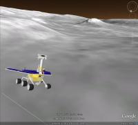
Aside from simply wanting to know what Spirit's final orientation is, I started working on this project because I wanted to be able to insert a rover model into the virtual 3D space of Google Mars. Ultimately, I wanted to be able to generate Google Mars anaglyphs similar to the ones I posted for Opportunity's route to Endeavour almost a year ago. Because Google has a high resolution DEM of Spirit's Inner Valley location, I thought it would be interesting to try some close up views of the terrain with a model of Spirit in context. Ultimately, I would like to create an image in tribute to Spirit's historic mission. But, I need to work the bugs out of the process, first.
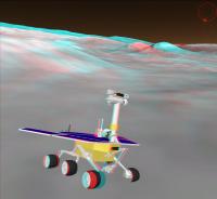
 To give you an idea of what I am talking about, here are a couple of preliminary images. The model in these images is using the orientation angles that James posted above, so you can see how they look next to Home Plate. First, here is a screenshot of a scene from Google Mars.
This is synthesized anaglyph view of Spirit's final location.
-------------------- ...Tom
I'm not a Space Fan, I'm a Space Exploration Enthusiast. |
||
|
|
|
||
 |

|
Lo-Fi Version | Time is now: 13th May 2024 - 05:33 AM |
|
RULES AND GUIDELINES Please read the Forum Rules and Guidelines before posting. IMAGE COPYRIGHT |
OPINIONS AND MODERATION Opinions expressed on UnmannedSpaceflight.com are those of the individual posters and do not necessarily reflect the opinions of UnmannedSpaceflight.com or The Planetary Society. The all-volunteer UnmannedSpaceflight.com moderation team is wholly independent of The Planetary Society. The Planetary Society has no influence over decisions made by the UnmannedSpaceflight.com moderators. |
SUPPORT THE FORUM Unmannedspaceflight.com is funded by the Planetary Society. Please consider supporting our work and many other projects by donating to the Society or becoming a member. |
|