MSL Images & Cameras, technical discussions of images, image processing and cameras |

  |
MSL Images & Cameras, technical discussions of images, image processing and cameras |
 Dec 28 2015, 05:12 PM Dec 28 2015, 05:12 PM
Post
#481
|
|
|
Senior Member  Group: Members Posts: 2507 Joined: 13-September 05 Member No.: 497 |
QUOTE (ugordan @ Dec 28 2015, 09:05 AM)  I would submit that this is the reason navcams look underexposed, they don't appear to use the square root encoding the color cameras do. They could use a similar scaling, but this capability seems to be rarely used. For MER, from http://onlinelibrary.wiley.com/doi/10.1029/2007JE003003/full QUOTE Employing a roughly square-root LUT can thus allow the image size (in bits) to be reduced without losing statistically significant information. While most Pancam images utilize this ability [Bell et al., 2006], only 12.6% of Navcam images acquired through the first 1000 sols have been scaled to 8 bits per pixel. This is probably to simplify the onboard stereo processing, but I'm not certain. -------------------- Disclaimer: This post is based on public information only. Any opinions are my own.
|
 |
 
|
|
Dec 29 2015, 01:29 AM
Post
#482
|
|
 Senior Member Group: Members Posts: 3419 Joined: 9-February 04 From: Minneapolis, MN, USA Member No.: 15 |
We had this problem when MSL first landed, that the navcams in particular looked really, really dark. And the mastcam images looked rather dark, too. Sometime in the first two months after landing, though, they brightened up considerably; the scaling was obviously adjusted. The example ugordan posted looks a lot like those early navcams. I wonder if something got reset back to the original scaling rather than the scaling they've been using for the past three years...?
I do recall posting, in the first month after landing, that the darkness of the images rather defeated their purpose for public outreach. I said that people would say "Why is this place such a darker, gloomier place than the other places on Mars we've landed?" when the only thing that's happening is that the scaling on the MSL images is very different from that used on the images returned by earlier landers. But the problem did go away -- at least until now. -the other Doug -------------------- The trouble ain't that there is too many fools, but that the lightning ain't distributed right. -Mark Twain
|
|
|
|
|
Jan 9 2016, 10:36 AM
Post
#483
|
||
 Junior Member Group: Members Posts: 30 Joined: 8-September 14 From: London, UK Member No.: 7254 |
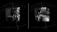
QUOTE (Gerald @ Sep 4 2013, 12:06 AM) I've been asked for an explanation of how I do the NavCam x-eyeds, and about possible algorithms to do it in an automatical way. The first part is easy to answer: I'm using Paint and manually crop those parts of the images which aren't visible in both images. The question about algorithms is tightly coupled to the inference of a 3d mesh, and related to the recent AutoNav adjustments necessary due to temperature-dependent NavCam B pointing. Therefore I'll try to give a very much simplified answer in this thread, based on the Sol 379 images NLB and NRB. Thanks Gerald for this intriguing explanation. I note that the stereo pair that you used in this example was a "distance" shot. Has anyone succeeded in making stereo images of closer views taken as navcam stereo pairs? I'm looking into why the stereo / VR (Google Cardboard) mode works so poorly in my Mars View app that I'm working on. My initial impression is that at least one major part of it is that the parallax is so ridiculously large that stereo pairs barely overlap at all unless they're looking into the distance. For example, I'm attaching a screenshot where I articificially restricted the render to a single stereo pair looking onto the rover's deck on sol 2. The source images are NLA, NRA. As you can see, the two images are each about centered in each eye's view (in my renderer, I pretend that the observer's eyes are approximately where there two cameras were), but the contents of the two images barely overlap at all because of the ridiculous amount of parallax. Based on the metadata, the left and right Navcam A cameras were 42.4cm apart when the image was taken (2012-08-08T07:16:06.450Z), which surprises me because I thought the distance was actually 26.5cm - does anyone know the correct value? Clearly either value is much larger than the pupil distance in humans (6.2cm) so it's normal that the parallax is large; the fact that the navcams only have a FOV of 45 degrees when human eyes have something like 70 degrees makes things worse. Why are the Navcams so far apart? Were they simply not designed for stereo viewing of anything that's less than 10 meters or so away? Do people combine different images (not from the same stereo pair) for close-up stereos? Is there something else that I'm missing?
Attached thumbnail(s)
|
|
|
|
|
|
|
Jan 9 2016, 02:44 PM
Post
#484
|
|
|
Junior Member Group: Members Posts: 30 Joined: 8-September 14 From: London, UK Member No.: 7254 |
PS. 42.4cm seems to be the correct value for the navcams' stereo baseline because that value also occurs in https://www-robotics.jpl.nasa.gov/publicati...ne/fulltext.pdf
What software / algorithm /metadata source does everyone use to correlate the stereo pairs to infer parallax and thus distance? Your own software, some standard software, or are you getting that metadata somewhere out of the PDS? (Currently I only use json.jpl.nasa.gov which was a quick way to get started, so I'd hate to change, but that backend has loads of issues such as missing data and server errors; so I may be forced to go find a new source for my metadata). |
|
|
|
|
Jan 9 2016, 03:52 PM
Post
#485
|
|
 Senior Member Group: Members Posts: 4246 Joined: 17-January 05 Member No.: 152 |
Yeah, 42.4 cm is correct. The mastcams are separated by 24.5 cm.
I only rarely use navcam parallax to measure distance, so I usually do it manually (align L/R frames on horizon, measure angular displacement for nearby object of interest, convert to distance using trig). I've also used the code AlgorimancerPG. As for "Why are the Navcams so far apart?", I think the answer is simply that the stereo imaging is used primarily to build a 3D model of the surface, not for stereo viewing by people. So the greater the separation the better the accuracy of the depth determinations. |
|
|
|
|
Jan 17 2016, 07:55 AM
Post
#486
|
|
|
Junior Member Group: Members Posts: 30 Joined: 8-September 14 From: London, UK Member No.: 7254 |
QUOTE (James Sorenson @ Aug 19 2012, 06:07 AM) PTgui has an option for Vignetting Correction. Any suggestions for how to best do it automatically (without manual intervention) from a command line? I'd like to reduce the vignetting in the images that I use in my Mars View app (currently based on EDR images), but I'd like to do all of them at once rather than one by one. |
|
|
|
|
Jan 17 2016, 10:09 AM
Post
#487
|
|
 Member Group: Members Posts: 691 Joined: 21-December 07 From: Clatskanie, Oregon Member No.: 3988 |
I don't have any idea's for applying with command line. However, over the years, I have found ways of doing it automatically fast and in bulk when I process my images and is one of the first things I try to eliminate in the images as much as possible. I apply flat images made using skyflats taken of the sky at different points in the mission. I do this and all the rest of the processing that has to be done to the raw images using simple Photoshop batch actions that batch processes them and spits them all out into a folder then I stitch them all together. I suppose a command line program could be developed that could apply these flat frames fairly easy with some sort of image processing tool kit. I'm sure others can chime in on other strategies of removing the vignetting that they do with the images or know of.
 If you want, I can present an example image from my process to show how effective it is. It's always a fun and at times frustrating learning process not just with this technique but finding other ways to improve on the processing of the images.
|
|
|
|
|
Jan 17 2016, 08:45 PM
Post
#488
|
|
|
Junior Member Group: Members Posts: 30 Joined: 8-September 14 From: London, UK Member No.: 7254 |
QUOTE (James Sorenson @ Jan 17 2016, 08:09 PM) I don't have any idea's for applying with command line. However, over the years, I have found ways of doing it automatically fast and in bulk when I process my images and is one of the first things I try to eliminate in the images as much as possible. I apply flat images made using skyflats taken of the sky at different points in the mission. I do this and all the rest of the processing that has to be done to the raw images using simple Photoshop batch actions that batch processes them and spits them all out into a folder then I stitch them all together. I suppose a command line program could be developed that could apply these flat frames fairly easy with some sort of image processing tool kit. I'm sure others can chime in on other strategies of removing the vignetting that they do with the images or know of. If you want, I can present an example image from my process to show how effective it is. It's always a fun and at times frustrating learning process not just with this technique but finding other ways to improve on the processing of the images. I'm guessing the flat field that you've developed consists of two theoretical images that represent what the sensor would yield when photographing a homogenously 1.) dark, 2.) light environment? I assume they're specific to a particular instrument (e.g. to the navcams)? Are those available without license restrictions (e.g. public domain) somewhere? I'm kind of surprised that this part of the sensor calibration isn't already done for the data available in the PDS. I haven't really looked at the RDR data yet because my data source (json.jpl.nasa.gov) only has EDR images I believe. But I looked through the data product types on the analyst's notebook and couldn't find any product type that was corrected for vignettes. I am thinking of switching to the PDS as a data source for other reasons, mostly because of the stereo disparity info (DSG, DSP, DDD, MDS products etc.) which will be useful for stereo images. The radiometrically corrected (linearized) Hazcam images (RAD and LIN products) are also interesting. If there was any vignette-corrected product in the PDS EDR data, that'd give me additional incentive to switch to the PDS. Update, I just found that there are flat fields in the PDS, e.g. here is the flat field for left navcam A, based on that instrument's serial number being 206. I guess the expectation is that I'll apply that flat field myself, as opposed to downloading images with the flat field correction already applied? I'm also not sure whether the files with the _V1 suffix are later or earlier revisions than those without (I'm guessing earlier). |
|
|
|
|
Jan 17 2016, 09:30 PM
Post
#489
|
|
|
Senior Member Group: Members Posts: 2507 Joined: 13-September 05 Member No.: 497 |
QUOTE (yogi @ Jan 17 2016, 12:45 PM) I'm kind of surprised that this part of the sensor calibration isn't already done for the data available in the PDS. I haven't really looked at the RDR data yet... EDRs are never corrected/flat-fielded because they represent the least-processed form of the data. In the list you linked to, "rad-corrected" RDRs would typically be flat-fielded, though I haven't looked at the engineering camera products. Some of the MMM RDR products are radiometrically corrected and some aren't, the RDR subtypes are not captured in the list you linked to. -------------------- Disclaimer: This post is based on public information only. Any opinions are my own.
|
|
|
|
|
Jan 17 2016, 10:13 PM
Post
#490
|
|
|
Member Group: Members Posts: 691 Joined: 21-December 07 From: Clatskanie, Oregon Member No.: 3988 |
As to what Mike said, the PDS EDR's don't have any correction applied, the RDR's do. If you were going to download PDS images in your app, which by the way, they are larger in file size, and you will have to work with the PDS format, you should use the RDRs.However, if you were going to use the raw images from the JPL website for the correction, you would also want to use skyflats that have already had the same stretch applied to them as the raw images. Applying a flatfield from PDS to the raw images just wouldn't work. When I get the chance later, I'll post an example.
Edit: Oh and yes Navcams, Mastcams, and MAHLI routinely take their own skyflats that can be made into flatfields. For Mastcam and MAHLI, they are usually taken full-frame which is 1600x1200. Most images though returned in the images are usually subframed to something like 1200x1200 or 1344x1200. Because of this, when I apply a flatfield, knowledge of how those images were subframed isn't really known in the raws, so I used the crud on the CCD as a fixed reference to align the full frame flatfields to the subframed images since the crud on both frames doesn't move. That way, I have cropped flatfields for all subframed sizes.
|
|
|
|
|
Jan 18 2016, 03:01 AM
Post
#491
|
|
|
Member Group: Members Posts: 691 Joined: 21-December 07 From: Clatskanie, Oregon Member No.: 3988 |
Here is some examples that I quickly through together with as little processing as possible.
 Raw mosaic. No processing on the individual images, just stitched.  Flat-fielded mosaic, no image to image brightness correction. 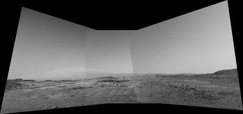 Same, but just seam blended. 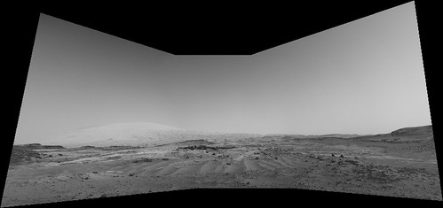 Here is the left Navcam flat-field for the raw's that I made. 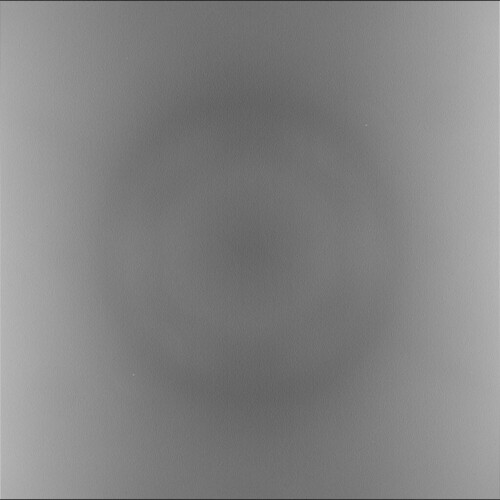 These recent post's really should be moved to the MSL images and cameras thread.
|
|
|
|
|
Jan 18 2016, 09:22 PM
Post
#492
|
|
|
Junior Member Group: Members Posts: 30 Joined: 8-September 14 From: London, UK Member No.: 7254 |
Those look awesome, thanks! I'll look at the images from the PDS and will see if I find suitable RDRs that already had the flat-field applied.
The step I'm most interested in is the seam blending, which I know nothing about. In Mars View I currently only do alpha blending (I make the borders of the images slightly transparent) - I'll have to read up on different blending algorithms and see if I can implement any myself or use third party software. The NASA Vision Workbench may be suitable for preprocessing? My app downloads the images from my website, so I can do any preprocessing that I want to the images that I'm hosting; only the last step of stitching the preprocessed (i.e. hopefully flat-fielded and otherwise adjusted) images will happen on the mobile device. |
|
|
|
|
Jan 19 2016, 06:41 PM
Post
#493
|
|
|
Member Group: Members Posts: 923 Joined: 10-November 15 Member No.: 7837 |
Many thanks for your post James... super informative!
-------------------- |
|
|
|
|
Jan 20 2016, 12:50 AM
Post
#494
|
|
 Administrator Group: Admin Posts: 5172 Joined: 4-August 05 From: Pasadena, CA, USA, Earth Member No.: 454 |
QUOTE (James Sorenson @ Jan 17 2016, 07:01 PM) These recent post's really should be moved to the MSL images and cameras thread. The posts seemed to make a wrong turn into the post-landing thread; I gently corrected their course and they have now found their way into the correct thread.
-------------------- My website - My Patreon - @elakdawalla on Twitter - Please support unmannedspaceflight.com by donating here.
|
|
|
|
|
Apr 4 2016, 10:09 AM
Post
#495
|
||
|
Junior Member Group: Members Posts: 30 Joined: 8-September 14 From: London, UK Member No.: 7254 |
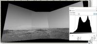
James - I noticed that your mosaic used the available range of intensities pretty well (see histogram.jpg attached to this post). Did you figure out the right calibration (multiplication factor plus an additive offset) by trial and error or did you use some deterministic approach that could be used for automatic processing?
I've noticed that the navcam RAD (radiometrically corrected) products from the PDS are very dark (I think they're 12bit values). Of course I can stretch their intensity but the required factors don't quite seem to be consistent across different images. I could of course do a histogram across all of the images that I want to combine in one mosaic, and then find the right shared calibration parameters to e.g. put 99.9% of pixels across the images into the band 0..255 of 8bit intensities. Is there a better way?
Attached thumbnail(s)
|
|
|
|
|
|
|

|
Lo-Fi Version | Time is now: 16th April 2024 - 09:24 AM |
|
RULES AND GUIDELINES Please read the Forum Rules and Guidelines before posting. IMAGE COPYRIGHT |
OPINIONS AND MODERATION Opinions expressed on UnmannedSpaceflight.com are those of the individual posters and do not necessarily reflect the opinions of UnmannedSpaceflight.com or The Planetary Society. The all-volunteer UnmannedSpaceflight.com moderation team is wholly independent of The Planetary Society. The Planetary Society has no influence over decisions made by the UnmannedSpaceflight.com moderators. |
SUPPORT THE FORUM Unmannedspaceflight.com is funded by the Planetary Society. Please consider supporting our work and many other projects by donating to the Society or becoming a member. |
|