Juno PDS data |

  |
Juno PDS data |
 Jan 10 2022, 08:56 PM Jan 10 2022, 08:56 PM
Post
#166
|
|
|
Senior Member  Group: Members Posts: 2511 Joined: 13-September 05 Member No.: 497 |
QUOTE (Brian Swift @ Jan 10 2022, 11:32 AM)  Does it seem sensible that the produced cubes are single rather than 3-band? There are a lot of things that don't seem sensible about ISIS. I think it would depend on your use case as to whether this was a feature or a bug. -------------------- Disclaimer: This post is based on public information only. Any opinions are my own.
|
 |
 
|
|
Jan 11 2022, 12:24 AM
Post
#167
|
|
|
Member Group: Members Posts: 890 Joined: 18-November 08 Member No.: 4489 |
QUOTE Does it seem sensible that the produced cubes are single rather than 3-band? how do you know that they are single band ? the few that i have processed with isis are rgb |
|
|
|
|
Jan 11 2022, 04:35 AM
Post
#168
|
|
|
Member Group: Members Posts: 406 Joined: 18-September 17 Member No.: 8250 |
QUOTE (JohnVV @ Jan 10 2022, 04:24 PM) how do you know that they are single band ? the few that i have processed with isis are rgb Viewing the cube produced by junocam2isis fullccd=yes with qview showed only 1 grey filter. Also processing the cube with explode only produced one file. I looked for a command that would report the number of filters/bands in a cube, but didn't see an obvious choice. |
|
|
|
|
Jan 13 2022, 10:09 PM
Post
#169
|
|
|
Member Group: Members Posts: 406 Joined: 18-September 17 Member No.: 8250 |
Note for anyone creating ISIS control networks for JunoCam data.
If you create a control network based on MissionJuno data, it won't "link" to ISIS cubes created from PDS data because the SerialNumber for the PDS cubes will be slightly different than MissionJuno based control network. The SerialNumber difference is because PDS StartTime has been improved/changed based on limb fit. |
|
|
|
|
Jan 13 2022, 11:10 PM
Post
#170
|
|
 Senior Member Group: Moderator Posts: 3233 Joined: 11-February 04 From: Tucson, AZ Member No.: 23 |
Can confirm. had to redo my PJ34 control network for the PDS release. thankfully, I didn’t feel the need to use quite so many points this time around, so it wasn’t quite as bad. Still needed jigsaw to change both camera angles and camera position to get a good solution. But the differences weren’t nearly as bad as with the MissionJuno PNG files. BTW, I saw your ISIS bug report. I’m having to use ISIS 5.0.2 for CaSSIS and JunoCAM due to a jigsaw bug in 6.0 with push-frame cameras that require the use of observations mode in jigsaw.
-------------------- &@^^!% Jim! I'm a geologist, not a physicist!
The Gish Bar Times - A Blog all about Jupiter's Moon Io |
|
|
|
|
Jan 19 2022, 09:43 PM
Post
#171
|
|
|
Member Group: Members Posts: 406 Joined: 18-September 17 Member No.: 8250 |
The ISIS tool junocam2isis has a FULLCCD option which produces cubes with dimension 1648x1200 with image data in rows 441-568, 596-723, 751-878 (counting first row as 0). These values are offset by 15 from the start lines of 456, 611, and 766 mentioned at http://www.unmannedspaceflight.com/index.p...st&p=203948
Does anyone think this is correct? I just want to check before submitting a bug report since I'm relatively new to using ISIS. |
|
|
|
|
Jan 19 2022, 11:12 PM
Post
#172
|
|
|
Senior Member Group: Members Posts: 2511 Joined: 13-September 05 Member No.: 497 |
QUOTE (Brian Swift @ Jan 19 2022, 01:43 PM) Does anyone think this is correct? That doesn't sound correct to me, but I'm not sure what subsequent processing they are doing with such an image. If you could show that the lat/lon mapping for the same image pixel was different between a FULLCCD image and a one-band image, that would be definitive proof of an inconsistency somewhere. I'm not sure if you can back those start lines out from the info in the I kernel, but maybe. -------------------- Disclaimer: This post is based on public information only. Any opinions are my own.
|
|
|
|
|
Jan 19 2022, 11:42 PM
Post
#173
|
|
 IMG to PNG GOD Group: Moderator Posts: 2250 Joined: 19-February 04 From: Near fire and ice Member No.: 38 |
This seems strange but very similar numbers (441.52 etc.) appear in the junoAddendum005.ti kernel that comes with ISIS. I don't know how ISIS uses these values though so this might or might not be working correctly in ISIS.
|
|
|
|
|
Jan 20 2022, 12:23 AM
Post
#174
|
|
|
Senior Member Group: Members Posts: 2511 Joined: 13-September 05 Member No.: 497 |
QUOTE (Bjorn Jonsson @ Jan 19 2022, 03:42 PM) This seems strange but very similar numbers (441.52 etc.) appear in the junoAddendum005.ti kernel that comes with ISIS. Good catch. I suspect the issue is that that file says INS-61500_BORESIGHT_LINE = 600 when I don't think it is, but 600 - INS-61502_FILTER_OFFSET = 3.48, which is INS-61502_DISTORTION_Y in the official I kernel. So it may be that those two confusions/errors cancel out in their processing. -------------------- Disclaimer: This post is based on public information only. Any opinions are my own.
|
|
|
|
|
Jan 21 2022, 12:44 AM
Post
#175
|
|
|
Member Group: Members Posts: 406 Joined: 18-September 17 Member No.: 8250 |
QUOTE (Bjorn Jonsson @ Jan 19 2022, 03:42 PM) This seems strange but very similar numbers (441.52 etc.) appear in the junoAddendum005.ti kernel that comes with ISIS. I don't know how ISIS uses these values though so this might or might not be working correctly in ISIS. Thanks Bjorn, the INS-6150?_FILTER_OFFSET values in junoAddendum005.ti do control where the data is placed in the FULLCCD cubes. QUOTE (mcaplinger @ Jan 19 2022, 03:12 PM) If you could show that the lat/lon mapping for the same image pixel was different between a FULLCCD image and a one-band image, that would be definitive proof of an inconsistency somewhere. Thanks Mike, I took a look and lat/lon match up with about 0.5 pixel vertical difference, which I suspect is due to the current FILTER_OFFSET values having a 0.52 fractional part. If I change the FILTER_OFFSETs to the "standard" whole number values 292,457,612,767 and re-spiceinit the FULLCCD and one-band cubes, the alignment is exact. However, from junoAddendum004.ti to junoAddendum005.ti the FILTER_OFFSETs are changed to the current odd values with the comment: "2018-05-14 Jesse Mapel - Changed filter offsets to match code from M Caplinger." |
|
|
|
|
Jan 21 2022, 06:26 AM
Post
#176
|
|
|
Senior Member Group: Members Posts: 2511 Joined: 13-September 05 Member No.: 497 |
QUOTE (Brian Swift @ Jan 20 2022, 04:44 PM) However, from junoAddendum004.ti to junoAddendum005.ti the FILTER_OFFSETs are changed to the current odd values with the comment: "2018-05-14 Jesse Mapel - Changed filter offsets to match code from M Caplinger." I don't have any idea what they are doing with the junoAddendum005.ti file or why they need those values. My code only uses the values from the standard I kernel. It sounds like the error, if it is an error, is cancelled out by whatever they're doing in the code. I did some tests between my results and ISIS results a couple of years ago, and they matched at the eyeball level (1-2 pixels, perhaps better) so there are no gross discrepancies AFAIK. -------------------- Disclaimer: This post is based on public information only. Any opinions are my own.
|
|
|
|
|
Jan 21 2022, 06:40 PM
Post
#177
|
|
|
Member Group: Members Posts: 406 Joined: 18-September 17 Member No.: 8250 |
Mike,
Before I mention it to the ISIS folks, I just want to confirm that the below statement still stands. QUOTE (mcaplinger @ Oct 20 2013, 03:02 PM) ... The actual start lines for each 128-line band framelet relative to line 0 at the "top" of the sensor are 291, 456, 611, and 766 with the nominal optic axis at line 600. And the focal length is 10.997mm. Rephrased - the readout start lines 291, 456, 611, and 766 are relative to the 1200 row CCD "Active Pixels" area with rows numbered starting from 0. I assume the actual readout lines used by the instrument are 6 larger than these numbers to skip the 2 dark and 4 buffer rows, which is why "top" is in quotes in your description. I actually messed this up when building my camera model, and assumed the readouts were relative to the 1214 CCD total pixel rows. Just out of curiosity since I'm dragging you down memory lane, are the readout offsets A)parameters to every imaging command B)fixed in firmware C) fixed in flight software D)part of a table of instrument parameter sets in flight software that are selected by an imaging command parameter, E)Transmitted telepathically from the spice infused hamster running on a wheel aligned with Junos' spin axis? |
|
|
|
|
Jan 22 2022, 06:01 PM
Post
#178
|
|
|
Senior Member Group: Members Posts: 2511 Joined: 13-September 05 Member No.: 497 |
QUOTE (Brian Swift @ Jan 21 2022, 10:40 AM) I assume the actual readout lines used by the instrument are 6 larger than these numbers to skip the 2 dark and 4 buffer rows, which is why "top" is in quotes in your description. I don't think this is true, no. QUOTE are the readout offsets A)parameters to every imaging command B)fixed in firmware C) fixed in flight software D)part of a table of instrument parameter sets in flight software that are selected by an imaging command parameter... D except there is one set and it's always used by every imaging command. There are five parameters: how many lines to skip at the top during CCD readout (done in hardware in the camera head), and then how many lines to skip at the top of each 155-line band area to produce the 128 lines that are actually sent to the ground (done in software). 155-line regions for bands that aren't being taken in any given image are also skipped in hardware (at the top -- if you commanded an red/blue image the green would get read out and then thrown away in software because the hardware can't skip lines in the middle of a readout, only at the beginning.) I'll quote from the Junocam User's Guide, which says the same thing: QUOTE Junocam uses a color filter array with four spectral filter regions which is bonded to the surface of its CCD image sensor. The process of imaging reads out a single rectangular area of the CCD, and then the flight software edits that frame to omit areas between the filter regions which do not contain usable image data. The CCD map defines which areas correspond to which filter regions. Each region is nominally 155 lines high, and 128 lines are extracted for each color band. The CCD map consists of five entries: the starting line for band 1, and then the number of lines at the top of each 155-pixel-high region to skip to form the 128-line output. The default settings for the CCD map are 287, 4, 14, 14, 14. In the I kernel, I concentrated on describing how to do the geometric correction for the 128-line framelets we actually get on the ground, and never tried to describe in detail exactly where those pixels were coming from, and none of my processing ever tries to reconstruct the "original" frame like FULLCCD does. I think the ASCII drawing in the I kernel is accurate, but I wouldn't swear to it since none of my processing is doing anything with it. And to reiterate, my interaction with the ISIS team has been pretty minimal and I have not made an effort to understand their design choices, some of which seem odd to me. -------------------- Disclaimer: This post is based on public information only. Any opinions are my own.
|
|
|
|
|
Jan 23 2022, 12:14 AM
Post
#179
|
||
|
Member Group: Members Posts: 406 Joined: 18-September 17 Member No.: 8250 |
Thanks Mike, this is great info.
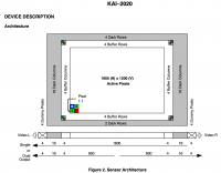
QUOTE (mcaplinger @ Jan 22 2022, 10:01 AM) I'll quote from the Junocam User's Guide, which says the same thing: Hmm, Junocam User's Guide isn't part of my JunoCam related documents collection. Is it a MSSS internal doc, or a JPL (or other agency) doc? I can see the functional description translates into effective readout lines as: 287 + 4 = 291 287 + 155 + 14 = 456 287 + 155 + 155 + 14 = 611 287 + 155 + 155 + 155 + 14 = 766 QUOTE I think the ASCII drawing in the I kernel is accurate, but I wouldn't swear to it ... Since these offsets are relative to very first line of CCD, the center reference in the ASCII diagram in juno_junocam_v03.ti is at offset 599.5 (291 start of methane + 63.5 to center of methane + 245 to diagram center reference.) This 599.5 is 6 lines from the center of the Active Pixels which is at offset 605.5=(6+1205)/2 where 6 and 1205 are the first and last lines of the Active Pixels area. Diagram of CCD layout from KAI-2020-D.PDF for anyone wondering where these CCD numbers come from:
QUOTE ...design choices, some of which seem odd to me. Nominally ISIS breaks each filter into a separate image. Based on the issues I've had with the FULLCCD option and responses at https://astrodiscuss.usgs.gov/t/should-juno.../797/5?u=bswift I have the impression that no one else has used it. |
|
|
|
|
|
|
Jan 25 2022, 04:47 PM
Post
#180
|
|
|
Senior Member Group: Members Posts: 2511 Joined: 13-September 05 Member No.: 497 |
QUOTE (Brian Swift @ Jan 22 2022, 04:14 PM) Based on the issues I've had with the FULLCCD option... I have the impression that no one else has used it. Certainly we didn't ask for this functionality, no other pushframe imager support in ISIS has it, and we weren't asked for, nor did we provide, any input about how pixels are mapped to CCD lines. I acknowledge that the I kernel is not very clear about what the CCD layout is; technically it doesn't need to be. I didn't concentrate on this because we were trying to get the framelet parameters all correct, and I believe they are. But how we got to that point is more confusing than one might hope. I did find a correction for the dark/buffer CCD rows buried in the parameter-fitting code that we used to update the I and frames kernel values from cruise star imaging. Unfortunately, near the end of that analysis we realized that the random timestamping errors were going to swamp any effort to get to subpixel precision on this, so what we have now is probably near the limit of what can be done. I will conclude by observing that camera models don't have to be "right" and often aren't, they just have to yield correct and consistent results. -------------------- Disclaimer: This post is based on public information only. Any opinions are my own.
|
|
|
|
|

|
Lo-Fi Version | Time is now: 27th April 2024 - 12:57 AM |
|
RULES AND GUIDELINES Please read the Forum Rules and Guidelines before posting. IMAGE COPYRIGHT |
OPINIONS AND MODERATION Opinions expressed on UnmannedSpaceflight.com are those of the individual posters and do not necessarily reflect the opinions of UnmannedSpaceflight.com or The Planetary Society. The all-volunteer UnmannedSpaceflight.com moderation team is wholly independent of The Planetary Society. The Planetary Society has no influence over decisions made by the UnmannedSpaceflight.com moderators. |
SUPPORT THE FORUM Unmannedspaceflight.com is funded by the Planetary Society. Please consider supporting our work and many other projects by donating to the Society or becoming a member. |
|