Juno perijoves 2 and 3, October 19 and December 11, 2016 |

Juno perijoves 2 and 3, October 19 and December 11, 2016 |
 Oct 26 2016, 04:44 PM Oct 26 2016, 04:44 PM
Post
#1
|
|
|
Junior Member  Group: Members Posts: 22 Joined: 13-October 13 Member No.: 7013 |
A lot has happened and it seemed like a good time to start a new post. We will be staying in 53 day orbits until the project has a full understanding of the risks that may or may not be associated with reducing the orbit period to 14 days per our previous plan.
|
 |
 
|
 |
|
Feb 3 2020, 11:48 PM
Post
#2
|
|
 IMG to PNG GOD Group: Moderator Posts: 2250 Joined: 19-February 04 From: Near fire and ice Member No.: 38 |
There is also clearly some misalignment far from the limb that can be seen by 'blinking' the red/green/blue channels rapidly in high contrast areas. The misalignment should be smaller. One important issue is that the x (sample) of the optical axis is *not* at the center (i.e. x=824) in the framelets. Depending on how you are creating these images this may be of importance but I'm not sure it's enough to cause all of the misalignment (in particular not the misalignment near the center of your images).
|
|
|
|
|
Feb 4 2020, 10:58 PM
Post
#3
|
|
|
Member Group: Members Posts: 406 Joined: 18-September 17 Member No.: 8250 |
QUOTE (Bjorn Jonsson @ Feb 3 2020, 03:48 PM)  ... 'blinking' the red/green/blue channels rapidly in high contrast areas. Doh. I should have already been doing this. I've just been looking at bue/red fringing in high contrast areas. Björn, are you using the standard camera model, or have you developed your own? |
|
|
|
|
Feb 7 2020, 01:01 AM
Post
#4
|
|
|
IMG to PNG GOD Group: Moderator Posts: 2250 Joined: 19-February 04 From: Near fire and ice Member No.: 38 |
QUOTE (Brian Swift @ Feb 4 2020, 10:58 PM) Björn, are you using the standard camera model, or have you developed your own? This depends on how you define "...using the standard camera model"  . I'm using software written by myself for the geometric processing (reprojecting the framelets to a simple cylindrical and/or polar map etc.). However, some of the code is directly based on information/code from the IK kernel, in particular the distort/undistort code, the location of R/G/B on the CCD, the FOV etc.. I'm also using the SPICE toolkit. Works wonderfully now, especially after lots of improvements I did in November and December 2019 (what was supposed to be a minor improvement in early November triggered a flood of new ideas for improving the software, resulting in faster processing, improved/proper flatfielding, a new (?) function for removing limb darkening, better photometric parameters, an empirical model of the skylight illumination near the terminator, easier limb fits etc.). . I'm using software written by myself for the geometric processing (reprojecting the framelets to a simple cylindrical and/or polar map etc.). However, some of the code is directly based on information/code from the IK kernel, in particular the distort/undistort code, the location of R/G/B on the CCD, the FOV etc.. I'm also using the SPICE toolkit. Works wonderfully now, especially after lots of improvements I did in November and December 2019 (what was supposed to be a minor improvement in early November triggered a flood of new ideas for improving the software, resulting in faster processing, improved/proper flatfielding, a new (?) function for removing limb darkening, better photometric parameters, an empirical model of the skylight illumination near the terminator, easier limb fits etc.).The only issue I'm working on now is the value I need to add to START_TIME. Using a fairly large sample of images it has become absolutely clear that in my case the average value I need to use is lower than the correct value (0.068). The average value I use is close to 0.040 but it varies and is sometimes close to 0.068. This means that something is wrong. This has no visual effect though and is in that sense not a serious problem (in particular there is negligible misalignment between the R/G/B channels or adjacent framelets from the same color channel). I can think of at least three plausible reasons for this (in fact all of them might contribute to the error) and now that I'm almost finished with the PJ24 images (at least for the time being) I plan on taking a detailed look at this issue. |
|
|
|
|
Feb 7 2020, 06:55 AM
Post
#5
|
|
|
Member Group: Members Posts: 406 Joined: 18-September 17 Member No.: 8250 |
QUOTE (Bjorn Jonsson @ Feb 6 2020, 05:01 PM) ... some of the code is directly based on information/code from the IK kernel, in particular the distort/undistort code, That is what I was I was referring to. I and (I believe) Gerrald have our own distort/undistort code, Kevin (I believe) is using the standard code via ISIS, but I didn't know if you had your own or used the standard code. QUOTE ... in faster processing, improved/proper flatfielding, a new (?) function for removing limb darkening, better photometric parameters, an empirical model of the skylight illumination near the terminator, easier limb fits etc.). Awesome. Wish I had time to do a proper illumination removal model. When you combine multiple images, is there residual brightness variation that needs to be adjusted to eliminate boundaries between images? QUOTE The only issue I'm working on now is the value I need to add to START_TIME. Using a fairly large sample of images it has become absolutely clear that in my case the average value I need to use is lower than the correct value (0.068). The average value I use is close to 0.040 but it varies and is sometimes close to 0.068. Note, the START_TIME_BIAS in juno_junocam_v03.ti is 0.06188 not .0688. My start times (based on limb fit) range from .03 to .08 |
|
|
|
|
Feb 9 2020, 11:40 PM
Post
#6
|
||||
|
IMG to PNG GOD Group: Moderator Posts: 2250 Joined: 19-February 04 From: Near fire and ice Member No.: 38 |
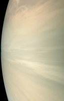
QUOTE (Brian Swift @ Feb 7 2020, 06:55 AM) QUOTE (Bjorn Jonsson) ... in faster processing, improved/proper flatfielding, a new (?) function for removing limb darkening, better photometric parameters, an empirical model of the skylight illumination near the terminator, easier limb fits etc.). Awesome. Wish I had time to do a proper illumination removal model. When you combine multiple images, is there residual brightness variation that needs to be adjusted to eliminate boundaries between images? Yes, there are always some differences and I don't think they can ever be eliminated. The reason is that the photometric parameters differ a bit for different parts of Jupiter (in particular I'm pretty sure that the parameters for the polar areas differ from the parameters closer to the equator) and they also vary as a function of time (changes in color/brightness/haze etc.), in other words: There's no such thing as a 'perfect' photometric model for Jupiter. For simplification purposes I'm using the same parameters everywhere. That said, the differences at the boundaries between images are much smaller now than they used to be when mosaicking images. Of course the intensity differences are smaller but what's maybe even more important is that there are now no significant color differences at the seams (unless there are significant differences in the emission angle). These smaller differences are not only because of more accurate photometric parameters when removing the illumination effects. I recently discovered that proper and accurate flat fielding is much more important when processing JunoCam images than I used to think. There is some vignetting in the raw images. The effects of flat fielding are not very noticeable in images with lots of high frequency, high contrast features but they are more noticeable in low contrast areas. Here is an image where the effects of flat fielding are particularly noticeable, an animated GIF example from image PJ14_26 (here the illumination has not been changed):
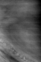
Needless to say the flat fielded images with illumination removed are easier to deal with when making mosaics. The flat fielding also greatly reduces the horizontal banding seen in some images, especially in the blue channel in hi-res images of low contrast areas. This is an example from the blue channel in image PJ10_28 without flat fielding. The contrast has been increased a lot:
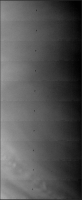
The individual framelets are too dark at the top and too bright at the bottom. Flat fielding greatly reduces this banding but does not completely eliminate it. The absence of an 'official' JunoCam flat field turned out to be a smaller problem than I was initially expecting. As a starting point I found a flat field image in this post from Mike. Using this image directly didn't work well (I tried all decompanded and not decompanded combinations to be sure). I had to make significant modifications to it in order for it to work well. This was largely a trial and error process involving mosaics where the difference in emission angle is small in the overlap area, checking images where I knew that the brightness near the right edge shouldn't be lower than near the center and also by checking for the horizontal banding mentioned above. I ended up with a flat field that seems to work very well but I'll probably make further modifications to it later - importantly I really have no idea exactly how close it is to a 'perfect' flat field. This is the flat field I'm currrently using:
Apart from other changes, high frequency artifacts, blemishes etc. have been removed since I prefer to fix these in a separate processing step and not as part of the flat fielding. Has anyone else been flat fielding the JunoCam images and if so, how? QUOTE (Brian Swift @ Feb 7 2020, 06:55 AM) Note, the START_TIME_BIAS in juno_junocam_v03.ti is 0.06188 not .0688. My start times (based on limb fit) range from .03 to .08 Oops, I didn't look up the correct value before writing the incorrect value 0.068 but it doesn't change the fact that the ~0.040 value I mentioned is suspiciously low. The range I have seen (also from limb fits) is slightly bigger, ~0.005 to ~0.085. QUOTE (Gerald @ Feb 7 2020, 11:25 AM) My assumptions about camera pointing are imperfect, and I'm doing some manual limb fitting of each image. ... Regarding the limb fit: Note, that the opacity of the hazes, and so the apparent limb, is varying with latitude. This applies to Jupiter's equipotential wrt to a spheroid, too. (AFAIK, full detail of the latter isn't publicly accessible, yet.) I'm also measuring the limb position in every image I process - I've sometimes had the impression that this was rare. I then feed the measured limb positions into software that gives me the START_TIME and interframe delay that are consistent with the measured limb positions. Hazes, variable cloud altitudes etc. greatly complicate this though. Also the appearance of the limb in the blue images is significantly different from the red (and also green) images and this affects the limb position measurements. Maybe I should measure the limb positions from red images only. |
|||
|
|
|
|||
|
Feb 11 2020, 08:07 PM
Post
#7
|
||
|
Member Group: Members Posts: 406 Joined: 18-September 17 Member No.: 8250 |
QUOTE (Bjorn Jonsson @ Feb 9 2020, 03:40 PM) Has anyone else been flat fielding the JunoCam images and if so, how? My flat fields (gains) were derived from average of 150 bright framelets (30 from each of PJ12 to PJ16) which are smoothed by fitting with a 10th order polynomial. Dark spots in average are merged into the polynomial based flat. I've uploaded to GitHub depot the gain, flat (not used), and debias images as 32-bit tiff. https://github.com/BrianSwift/JunoCam/tree/master/Juno3D An animated gif showing effect of flat field on PJ10_28 blue channel
QUOTE ... I then feed the measured limb positions into software that gives me the START_TIME and interframe delay that are consistent with the measured limb positions. I only use limb fits to adjust START_TIME. Centering the SPICE limb within the visible limb using average of time offset computed independently for R,G,B. I assume variance in altitude of visible limb is due to real atmospheric variation relative to the SPICE ellipsoid. I'm unaware of any physical justification for varying interframe delay. |
|
|
|
|
|
 Candy Hansen Juno perijoves 2 and 3 Oct 26 2016, 04:44 PM
 Candy Hansen At the press conference last week I showed many be... Oct 26 2016, 04:46 PM
 Candy Hansen At this moment we are trying to find the best time... Oct 26 2016, 04:49 PM
 Roman Tkachenko QUOTE (Candy Hansen @ Oct 26 2016, 08:46 ... Oct 27 2016, 12:56 AM Glenn Orton Until and unless we figure out how to fix or find ... Oct 28 2016, 09:34 PM JRehling I'm curious, should the engine problem be unre... Oct 28 2016, 11:38 PM elakdawalla Here's a good article from Spaceflight Now tha... Oct 28 2016, 11:53 PM JRehling Thanks for the link, Emily. That's pretty reas... Oct 29 2016, 03:19 AM elakdawalla I was going to make a new thread for PJ3, but I re... Nov 2 2016, 07:25 PM Gerald Voting for PJ3 targets started. It will last anoth... Nov 25 2016, 04:45 PM MichaelJWP Normally an 'interested lurker' here, but ... Dec 12 2016, 10:35 AM mcaplinger QUOTE (MichaelJWP @ Dec 12 2016, 02:35 AM... Dec 12 2016, 03:29 PM MichaelJWP QUOTE (mcaplinger @ Dec 12 2016, 03:29 PM... Dec 12 2016, 06:58 PM Gerald New images have been scheduled to be published on ... Dec 12 2016, 12:00 PM Holder of the Two Leashes Here are the plans for P3: LINK
Last update on Tw... Dec 12 2016, 02:07 PM Gerald Goldstone is downlinking data with 119.57 kb/sec:
... Dec 12 2016, 02:27 PM mcaplinger PJ3 data posted -- https://www.missionjuno.swri.ed... Dec 13 2016, 10:51 PM Gerald A very first idea of #03C00107:
(image: NASA / JP... Dec 14 2016, 01:20 AM Gerald Other selected and enhanced Perijove-3 images as a... Dec 14 2016, 02:22 AM Gerald Preliminary PJ3 close-up RGBs, decompanded, color-... Dec 14 2016, 02:23 PM Gerald ... this is an ad-hoc attempt of post-processing w... Dec 14 2016, 02:32 PM JRehling Gerald, your work is very nice! Are you sure y... Dec 15 2016, 09:12 PM mcaplinger The Junocam ring image in processed form is buried... Dec 14 2016, 06:40 PM Explorer1 It's still an impressive first, seeing them fr... Dec 14 2016, 08:38 PM mcaplinger QUOTE (Explorer1 @ Dec 14 2016, 12:38 PM)... Dec 14 2016, 09:07 PM Explorer1 Oops, I should've been more specific, I meant ... Dec 14 2016, 09:48 PM mcaplinger QUOTE (Explorer1 @ Dec 14 2016, 01:48 PM)... Dec 14 2016, 10:07 PM Gerald Thanks! I felt like diving through the Mandelb... Dec 16 2016, 04:13 PM Gerald That's an enhanced crop of an intermediate map... Dec 16 2016, 05:28 PM Gerald This may serve as a small status update.
I'm w... Dec 18 2016, 06:12 AM Gerald This gif shows an attempt to fit the images into a... Dec 18 2016, 09:07 AM fredk QUOTE (Gerald @ Dec 18 2016, 10:07 AM) I... Dec 18 2016, 03:50 PM mcaplinger AFAIK, GR effects have never been part of the NAIF... Dec 18 2016, 05:03 PM Gerald I was just looking for a simple solution to adjust... Dec 18 2016, 06:32 PM mcaplinger QUOTE (Gerald @ Dec 18 2016, 10:32 AM) I... Dec 18 2016, 07:14 PM fredk QUOTE (Gerald @ Dec 18 2016, 07:32 PM) Si... Dec 18 2016, 07:20 PM Gerald Well, in order to solve the question about whether... Dec 18 2016, 07:59 PM fredk Taking this thread even farther from Jupiter, the ... Dec 18 2016, 08:33 PM Gerald By the equivalence principle "acceleration = ... Dec 18 2016, 09:17 PM mcaplinger QUOTE (Gerald @ Dec 18 2016, 01:17 PM) In... Dec 19 2016, 04:28 PM Gerald For those, who like to use the MSSS version of the... Dec 19 2016, 06:33 PM Gerald Crescent Jupiter:
For the PJ3 Approach sequence, I... Dec 21 2016, 08:00 PM Ant103 All I want to tell you Gerald : you are doing an A... Dec 21 2016, 08:31 PM Gerald QUOTE (Ant103 @ Dec 21 2016, 09:31 PM) Al... Dec 21 2016, 09:33 PM scalbers Regarding GR, in my numerical integration software... Dec 21 2016, 09:09 PM scalbers Gerald - here is the correction term for the orbit... Dec 21 2016, 11:11 PM Gerald This is an animated gif of preliminarily processed... Dec 22 2016, 06:46 AM mcaplinger QUOTE (Gerald @ Dec 21 2016, 10:46 PM) No... Dec 22 2016, 07:11 AM fredk QUOTE (mcaplinger @ Dec 22 2016, 08:11 AM... Dec 22 2016, 03:16 PM Gerald I see. Then the 'I' is likely used as an a... Dec 22 2016, 08:00 AM eliBonora Here a couple of PJ3 processing and a test anaglyp... Dec 22 2016, 08:27 AM Gerald Here a synopis of the PJ03 Approach Movie images:
... Dec 22 2016, 02:29 PM mcaplinger BTW, if people don't know about the work of Jo... Dec 22 2016, 02:52 PM Gerald QUOTE (mcaplinger @ Dec 22 2016, 03:52 PM... Dec 23 2016, 12:46 AM scalbers Also still used quite a bit in numerical weather p... Dec 22 2016, 05:38 PM Gerald PJ03 departure movie, RGB images, decompanded, lin... Jan 3 2017, 01:57 AM Gerald PJ03 Departure and Marble Movie, browsable RGB ima... Jan 3 2017, 04:10 AM Gerald Methane band PJ03 Departure Movie images (reduced,... Jan 3 2017, 10:31 PM Gerald ... And an example of a false-color image using th... Jan 3 2017, 10:34 PM Gerald One of four slightly different preliminary PJ03 an... Jan 6 2017, 03:06 PM Roman Tkachenko Crescent Jupiter with Great Red Spot Jan 9 2017, 04:11 PM Gerald Jupiter's vortices at and near the south pole,... Jan 10 2017, 05:12 PM PhilipTerryGraham Another lucky person has made it into the NASA Pho... Jan 20 2017, 01:48 AM Roman Tkachenko Jupiter's South Pole (PJ-3) Feb 1 2017, 08:42 PM wildespace PIA21378 - http://photojournal.jpl.nasa.gov/catalo... Feb 19 2017, 10:25 AM Gerald Despite Juno's safe mode around PJ02, JunoCam ... Jun 28 2017, 04:25 PM Gerald Synopsis of Perijove-03 subset:
Larger subset of... Sep 4 2017, 01:20 AM Gerald Last night, I've rendered three more versions ... Nov 6 2017, 02:12 PM Gerald The upload issue appears to be fixed. Great job... Nov 6 2017, 04:26 PM Gerald Perijove-03 flyby movie is on Youtube, and on juno... Dec 7 2017, 06:34 PM Sean Wow...the south pole is looking really good. Dec 7 2017, 07:48 PM Sean PJ03_114 [G.Eichstadt]
Details Dec 12 2017, 09:54 PM Sean PJ03_107 [G.Eichstadt]
Details Dec 13 2017, 12:54 AM Sean PJ03_117 [G.Eichstadt]
Details Dec 13 2017, 04:19 AM Sean PJ03_118 [G.Eichstadt]
Details
More comp... Dec 13 2017, 06:16 PM Gerald The anticyclone in PJ-03, #107, is called NN-LRS-1... Dec 13 2017, 09:10 PM Sean PJ03_117 update + detail [G.Eichstadt] Feb 19 2018, 05:21 PM Sean New detail pass on PJ03_114 [G.Eichstadt] Feb 26 2018, 01:34 AM Sean PJ03_120 updated + details [G.Eichstadt] Feb 26 2018, 12:34 PM Sean PJ03_120_v3 Yet another pass + details... Mar 6 2018, 01:47 AM Sean Yet another pass at PJ03_120... Aug 19 2018, 10:23 AM Floyd Seem hard to imagine you improving on your previou... Aug 19 2018, 03:55 PM Sean Thanks Floyd... the truth is for a couple of perij... Aug 19 2018, 08:52 PM Bjorn Jonsson I recently decided to take a look at data from the... Jul 10 2019, 09:02 PM adamg Contents of pds-imaging.jpl.nasa.gov/data/juno/JNO... Jan 17 2020, 09:03 PM adamg first elements in pds-imaging.jpl.nasa.gov/data/ju... Jan 17 2020, 09:13 PM adamg JNCE_2016287_02C10029_V01 and JNCE_2016346_03C0011... Jan 31 2020, 11:35 PM Brian Swift QUOTE (adamg @ Jan 31 2020, 03:35 PM) Fee... Feb 3 2020, 03:26 AM adamg The top edge of the second image looks a little bi... Feb 3 2020, 10:26 PM Gerald QUOTE (Brian Swift @ Feb 7 2020, 07:55 AM... Feb 7 2020, 11:25 AM Brian Swift QUOTE (Gerald @ Feb 7 2020, 03:25 AM) And... Feb 11 2020, 09:53 PM Gerald QUOTE (Brian Swift @ Feb 11 2020, 10:53 P... Feb 15 2020, 12:55 AM Bjorn Jonsson QUOTE (Brian Swift @ Feb 11 2020, 08:07 P... Feb 19 2020, 12:59 AM Brian Swift QUOTE (Bjorn Jonsson @ Feb 18 2020, 04:59... Feb 19 2020, 06:32 AM
Roman Tkachenko QUOTE (Candy Hansen @ Oct 26 2016, 08:46 ... Oct 27 2016, 12:56 AM Glenn Orton Until and unless we figure out how to fix or find ... Oct 28 2016, 09:34 PM JRehling I'm curious, should the engine problem be unre... Oct 28 2016, 11:38 PM elakdawalla Here's a good article from Spaceflight Now tha... Oct 28 2016, 11:53 PM JRehling Thanks for the link, Emily. That's pretty reas... Oct 29 2016, 03:19 AM elakdawalla I was going to make a new thread for PJ3, but I re... Nov 2 2016, 07:25 PM Gerald Voting for PJ3 targets started. It will last anoth... Nov 25 2016, 04:45 PM MichaelJWP Normally an 'interested lurker' here, but ... Dec 12 2016, 10:35 AM mcaplinger QUOTE (MichaelJWP @ Dec 12 2016, 02:35 AM... Dec 12 2016, 03:29 PM MichaelJWP QUOTE (mcaplinger @ Dec 12 2016, 03:29 PM... Dec 12 2016, 06:58 PM Gerald New images have been scheduled to be published on ... Dec 12 2016, 12:00 PM Holder of the Two Leashes Here are the plans for P3: LINK
Last update on Tw... Dec 12 2016, 02:07 PM Gerald Goldstone is downlinking data with 119.57 kb/sec:
... Dec 12 2016, 02:27 PM mcaplinger PJ3 data posted -- https://www.missionjuno.swri.ed... Dec 13 2016, 10:51 PM Gerald A very first idea of #03C00107:
(image: NASA / JP... Dec 14 2016, 01:20 AM Gerald Other selected and enhanced Perijove-3 images as a... Dec 14 2016, 02:22 AM Gerald Preliminary PJ3 close-up RGBs, decompanded, color-... Dec 14 2016, 02:23 PM Gerald ... this is an ad-hoc attempt of post-processing w... Dec 14 2016, 02:32 PM JRehling Gerald, your work is very nice! Are you sure y... Dec 15 2016, 09:12 PM mcaplinger The Junocam ring image in processed form is buried... Dec 14 2016, 06:40 PM Explorer1 It's still an impressive first, seeing them fr... Dec 14 2016, 08:38 PM mcaplinger QUOTE (Explorer1 @ Dec 14 2016, 12:38 PM)... Dec 14 2016, 09:07 PM Explorer1 Oops, I should've been more specific, I meant ... Dec 14 2016, 09:48 PM mcaplinger QUOTE (Explorer1 @ Dec 14 2016, 01:48 PM)... Dec 14 2016, 10:07 PM Gerald Thanks! I felt like diving through the Mandelb... Dec 16 2016, 04:13 PM Gerald That's an enhanced crop of an intermediate map... Dec 16 2016, 05:28 PM Gerald This may serve as a small status update.
I'm w... Dec 18 2016, 06:12 AM Gerald This gif shows an attempt to fit the images into a... Dec 18 2016, 09:07 AM fredk QUOTE (Gerald @ Dec 18 2016, 10:07 AM) I... Dec 18 2016, 03:50 PM mcaplinger AFAIK, GR effects have never been part of the NAIF... Dec 18 2016, 05:03 PM Gerald I was just looking for a simple solution to adjust... Dec 18 2016, 06:32 PM mcaplinger QUOTE (Gerald @ Dec 18 2016, 10:32 AM) I... Dec 18 2016, 07:14 PM fredk QUOTE (Gerald @ Dec 18 2016, 07:32 PM) Si... Dec 18 2016, 07:20 PM Gerald Well, in order to solve the question about whether... Dec 18 2016, 07:59 PM fredk Taking this thread even farther from Jupiter, the ... Dec 18 2016, 08:33 PM Gerald By the equivalence principle "acceleration = ... Dec 18 2016, 09:17 PM mcaplinger QUOTE (Gerald @ Dec 18 2016, 01:17 PM) In... Dec 19 2016, 04:28 PM Gerald For those, who like to use the MSSS version of the... Dec 19 2016, 06:33 PM Gerald Crescent Jupiter:
For the PJ3 Approach sequence, I... Dec 21 2016, 08:00 PM Ant103 All I want to tell you Gerald : you are doing an A... Dec 21 2016, 08:31 PM Gerald QUOTE (Ant103 @ Dec 21 2016, 09:31 PM) Al... Dec 21 2016, 09:33 PM scalbers Regarding GR, in my numerical integration software... Dec 21 2016, 09:09 PM scalbers Gerald - here is the correction term for the orbit... Dec 21 2016, 11:11 PM Gerald This is an animated gif of preliminarily processed... Dec 22 2016, 06:46 AM mcaplinger QUOTE (Gerald @ Dec 21 2016, 10:46 PM) No... Dec 22 2016, 07:11 AM fredk QUOTE (mcaplinger @ Dec 22 2016, 08:11 AM... Dec 22 2016, 03:16 PM Gerald I see. Then the 'I' is likely used as an a... Dec 22 2016, 08:00 AM eliBonora Here a couple of PJ3 processing and a test anaglyp... Dec 22 2016, 08:27 AM Gerald Here a synopis of the PJ03 Approach Movie images:
... Dec 22 2016, 02:29 PM mcaplinger BTW, if people don't know about the work of Jo... Dec 22 2016, 02:52 PM Gerald QUOTE (mcaplinger @ Dec 22 2016, 03:52 PM... Dec 23 2016, 12:46 AM scalbers Also still used quite a bit in numerical weather p... Dec 22 2016, 05:38 PM Gerald PJ03 departure movie, RGB images, decompanded, lin... Jan 3 2017, 01:57 AM Gerald PJ03 Departure and Marble Movie, browsable RGB ima... Jan 3 2017, 04:10 AM Gerald Methane band PJ03 Departure Movie images (reduced,... Jan 3 2017, 10:31 PM Gerald ... And an example of a false-color image using th... Jan 3 2017, 10:34 PM Gerald One of four slightly different preliminary PJ03 an... Jan 6 2017, 03:06 PM Roman Tkachenko Crescent Jupiter with Great Red Spot Jan 9 2017, 04:11 PM Gerald Jupiter's vortices at and near the south pole,... Jan 10 2017, 05:12 PM PhilipTerryGraham Another lucky person has made it into the NASA Pho... Jan 20 2017, 01:48 AM Roman Tkachenko Jupiter's South Pole (PJ-3) Feb 1 2017, 08:42 PM wildespace PIA21378 - http://photojournal.jpl.nasa.gov/catalo... Feb 19 2017, 10:25 AM Gerald Despite Juno's safe mode around PJ02, JunoCam ... Jun 28 2017, 04:25 PM Gerald Synopsis of Perijove-03 subset:
Larger subset of... Sep 4 2017, 01:20 AM Gerald Last night, I've rendered three more versions ... Nov 6 2017, 02:12 PM Gerald The upload issue appears to be fixed. Great job... Nov 6 2017, 04:26 PM Gerald Perijove-03 flyby movie is on Youtube, and on juno... Dec 7 2017, 06:34 PM Sean Wow...the south pole is looking really good. Dec 7 2017, 07:48 PM Sean PJ03_114 [G.Eichstadt]
Details Dec 12 2017, 09:54 PM Sean PJ03_107 [G.Eichstadt]
Details Dec 13 2017, 12:54 AM Sean PJ03_117 [G.Eichstadt]
Details Dec 13 2017, 04:19 AM Sean PJ03_118 [G.Eichstadt]
Details
More comp... Dec 13 2017, 06:16 PM Gerald The anticyclone in PJ-03, #107, is called NN-LRS-1... Dec 13 2017, 09:10 PM Sean PJ03_117 update + detail [G.Eichstadt] Feb 19 2018, 05:21 PM Sean New detail pass on PJ03_114 [G.Eichstadt] Feb 26 2018, 01:34 AM Sean PJ03_120 updated + details [G.Eichstadt] Feb 26 2018, 12:34 PM Sean PJ03_120_v3 Yet another pass + details... Mar 6 2018, 01:47 AM Sean Yet another pass at PJ03_120... Aug 19 2018, 10:23 AM Floyd Seem hard to imagine you improving on your previou... Aug 19 2018, 03:55 PM Sean Thanks Floyd... the truth is for a couple of perij... Aug 19 2018, 08:52 PM Bjorn Jonsson I recently decided to take a look at data from the... Jul 10 2019, 09:02 PM adamg Contents of pds-imaging.jpl.nasa.gov/data/juno/JNO... Jan 17 2020, 09:03 PM adamg first elements in pds-imaging.jpl.nasa.gov/data/ju... Jan 17 2020, 09:13 PM adamg JNCE_2016287_02C10029_V01 and JNCE_2016346_03C0011... Jan 31 2020, 11:35 PM Brian Swift QUOTE (adamg @ Jan 31 2020, 03:35 PM) Fee... Feb 3 2020, 03:26 AM adamg The top edge of the second image looks a little bi... Feb 3 2020, 10:26 PM Gerald QUOTE (Brian Swift @ Feb 7 2020, 07:55 AM... Feb 7 2020, 11:25 AM Brian Swift QUOTE (Gerald @ Feb 7 2020, 03:25 AM) And... Feb 11 2020, 09:53 PM Gerald QUOTE (Brian Swift @ Feb 11 2020, 10:53 P... Feb 15 2020, 12:55 AM Bjorn Jonsson QUOTE (Brian Swift @ Feb 11 2020, 08:07 P... Feb 19 2020, 12:59 AM Brian Swift QUOTE (Bjorn Jonsson @ Feb 18 2020, 04:59... Feb 19 2020, 06:32 AM |

|
Lo-Fi Version | Time is now: 29th April 2024 - 12:36 AM |
|
RULES AND GUIDELINES Please read the Forum Rules and Guidelines before posting. IMAGE COPYRIGHT |
OPINIONS AND MODERATION Opinions expressed on UnmannedSpaceflight.com are those of the individual posters and do not necessarily reflect the opinions of UnmannedSpaceflight.com or The Planetary Society. The all-volunteer UnmannedSpaceflight.com moderation team is wholly independent of The Planetary Society. The Planetary Society has no influence over decisions made by the UnmannedSpaceflight.com moderators. |
SUPPORT THE FORUM Unmannedspaceflight.com is funded by the Planetary Society. Please consider supporting our work and many other projects by donating to the Society or becoming a member. |
|