MSL Images & Cameras, technical discussions of images, image processing and cameras |

  |
MSL Images & Cameras, technical discussions of images, image processing and cameras |
 Apr 4 2016, 01:14 PM Apr 4 2016, 01:14 PM
Post
#496
|
||
 Junior Member  Group: Members Posts: 30 Joined: 8-September 14 From: London, UK Member No.: 7254 |
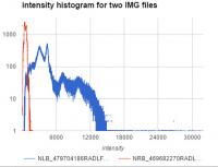
To give a more concrete example, compare the IMG files for these two RAD images:
NRB_469682270RADLF0441546NCAM00223M1 ("dark") vs. NLB_479704186RADLF0450852NCAM00279M1 ("bright"). The derived PNGs linked above have similar average brightness, but their distribution of the grayscale intensities in the underlying IMG files differ by a factor of 10-20x: * the one I call "dark" has intensity values up to 1754, with most values being <= 1284 * the one I call "light" has intensity values up to 32446, with most values being <= 14960 See the attached histogram.jpg for a direct comparison of the greyscale histograms across the two .IMG files. I've used my own software to parse those .IMG files, but I've confirmed that they also have vastly different brightness under IMG2PNG, so I don't think it's a bug in my software. Since the PNGs linked above have similar brightness, they must have been calibrated / stretched differently. Question: What approach do you folks use for calibrating greyscale intensity / brightness for mosaics?
Attached thumbnail(s)
|
|
 |
 
|
|
|
Apr 4 2016, 01:18 PM
Post
#497
|
|
|
Member Group: Members Posts: 890 Joined: 18-November 08 Member No.: 4489 |
for pds img/lbl files i use ISIS3 from the USGS/JPL
but this tool is not the best for working with the MSL images so using the flat image in the pds archive and gmic or Nip2 ( both handle 32 bit float ) is what i use |
|
|
|
|
Apr 4 2016, 04:26 PM
Post
#498
|
|
 Martian Photographer Group: Members Posts: 352 Joined: 3-March 05 Member No.: 183 |
"Dark" was taken within an hour of sunset; "bright" was in early afternoon with well lit bright stuff. So Mars is responsible for the different levels. Auto-expose, with the default stretching of public images, is responsible for the apparent similarity.
|
|
|
|
|
Apr 4 2016, 07:43 PM
Post
#499
|
|
 Member Group: Members Posts: 691 Joined: 21-December 07 From: Clatskanie, Oregon Member No.: 3988 |
QUOTE (yogi @ Apr 4 2016, 02:09 AM)  James - I noticed that your mosaic used the available range of intensities pretty well (see histogram.jpg attached to this post). Did you figure out the right calibration (multiplication factor plus an additive offset) by trial and error or did you use some deterministic approach that could be used for automatic processing? Nope, that was the direct result of applying a flatfield image to the contrast stretched images. Might be the way I apply it which is by no means a scientific and probably not the ideal way for flatfielding, which I just simply paste the flatfield onto the image and lower the opacity down to 30 or 40 percent. This reduces that stretching of the histogram whIle also reducing the vignetting. For Mastcams, I do it slightly differently. Why not scale the images using a fixed RADIANCE_OFFSET value to the RADIANCE_SCALING_FACTOR values in the lbl files? I believe this is what the Midnight Planets app does, and also IMG2PNG does this as well. This should scale all the images basically to the same defined fixed value. |
|
|
|
|
Apr 5 2016, 04:09 AM
Post
#500
|
|
|
Junior Member Group: Members Posts: 30 Joined: 8-September 14 From: London, UK Member No.: 7254 |
QUOTE (James Sorenson @ Apr 5 2016, 06:43 AM) Why not scale the images using a fixed RADIANCE_OFFSET value to the RADIANCE_SCALING_FACTOR values in the lbl files? I believe this is what the Midnight Planets app does, and also IMG2PNG does this as well. This should scale all the images basically to the same defined fixed value. Which LBL files do you mean, those for the RAD files? I should have mentioned that the RADIANCE_OFFSET and RADIANCE_SCALING_FACTOR in those is the same for all/most images, including the two that I posted here as an example; they both have: MSL:RADIANCE_OFFSET = 0.0 <W.m**-2.sr**-1.nm**-1> MSL:RADIANCE_SCALING_FACTOR = 1.0e-05 <W.m**-2.sr**-1.nm**-1> Stupid question (I don't have an image processing background): What exactly does "radiometrically corrected" mean for the RAD products? I didn't find where the MSL camera SIS defined this properly. I previously had checked out Wikipedia's article for the term which mentions corrections for "sun angle". This made me think that they were corrected for time of day, however per Deimos's comment above this seems to not be the case; since the units given are absolute physical units, I should perhaps have realized this earlier. Any other ideas for how I could determine the correct offset & scaling factor for RAD products? Should I be looking at a product type other than RAD? |
|
|
|
|
Apr 5 2016, 03:16 PM
Post
#501
|
|
 Administrator Group: Admin Posts: 5172 Joined: 4-August 05 From: Pasadena, CA, USA, Earth Member No.: 454 |
I think maybe you are looking for IOF products ("I over F" or radiance factor images). Check the MSL camera software interface specification, available here.
-------------------- My website - My Patreon - @elakdawalla on Twitter - Please support unmannedspaceflight.com by donating here.
|
|
|
|
|
Apr 5 2016, 04:32 PM
Post
#502
|
|
|
Senior Member Group: Members Posts: 2511 Joined: 13-September 05 Member No.: 497 |
I don't know of any product that compensates for time of day. Radiometric correction is just making the conversion from pixel value to absolute radiance unit. Since sun angle varies wildly over the scene regardless of the time of day, how are you going to correct for that in general?
If you have to mosaic images taken at different times of day (which are problematic for other reasons, shadows don't match, etc) you have to use some kind of empirical matching technique. -------------------- Disclaimer: This post is based on public information only. Any opinions are my own.
|
|
|
|
|
Apr 6 2016, 07:05 AM
Post
#503
|
|
|
Junior Member Group: Members Posts: 30 Joined: 8-September 14 From: London, UK Member No.: 7254 |
QUOTE (elakdawalla @ Apr 6 2016, 02:16 AM) I think maybe you are looking for IOF products ("I over F" or radiance factor images). Check the MSL camera software interface specification, available here. Where do I find those IOF products? They don't appear under MSLNAV_1XXX/ - see the spreadsheet I made of all of the Navcam RDR products occurring in the INDEX and their corresponding semantics, in order to figure out which products I need. Several products mentioned in the Software Interface Specification are missing from the PDS MSLNAV_1XXX dump (maybe they don't exist for navcam images?); are they accessible somewhere? For example, - the IOF products that Emily mentioned, - RIE products, which are corrected for "instrument effects only" (which I guess means vignettes / flat fields) - .BRT files (brightness corrections applied to the files used for the MOSaics) - these are mentioned on page numbered 75 in the SIS What am I missing? mcaplinger - sure, it may not be necessary to assemble images from completely different times of days into the same mosaic, but it'd still be nice to at least - know the brightness corrections applied to those images that were used in the official MOSaic products, - have versions of the remaining images that calibrated to a reasonable intensity range and without the vignettes (the RIE products might be this) My current concrete goal is to fix the images displayed in my Mars View app to not have those ugly vignettes, but I'm also hoping to incorporate the official precomputed mosaics. |
|
|
|
|
Apr 6 2016, 02:35 PM
Post
#504
|
|
|
Martian Photographer Group: Members Posts: 352 Joined: 3-March 05 Member No.: 183 |
There are many file types that are defined, but not produced on a regular basis or at all. For Navcam, I am not sure there is an 'IOF' generation. There is no cal target imaging campaign to characterize downwelling flux. The quick and dirty IOF calibration is to divide by the solar flux at Mars (function of camera+filter & Sun-Mars distance) and by the cosine of the solar zenith angle. The first is one you can skip for relative comparisons of images the same day or week. The second can be done with information in the image label (solar elevation).
That will go a long way to correcting for time of day, but it will probably not do well with a difference as extreme as posted above. As mcaplinger noted, there are important things other than overall light level, and these will not match across big gaps in time. Also, for the RAD products: Pancam corrections attempt to match the physical units noted above. Navcam products are directly proportional to physical units, but the quoted units shouldn't be taken too literally. |
|
|
|
|
Apr 14 2016, 11:24 PM
Post
#505
|
|||
 Member Group: Members Posts: 244 Joined: 2-March 15 Member No.: 7408 |
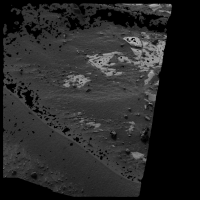
This discussion made me curious, so I ran an experiment to see if (or to what extent) it were possible to remove the effects of lighting from NAVCAM images.
From the LBLs, I pulled out the date/time, radiance offset, radiance scaling factor, solar elevation, sun view direction, site->rover frame transformations, and camera model parameters. I also pulled a bunch of constants for Mars from the Internet. I then read in the RAD, MXY, XYR, and UVW data and tried to calculate the solar irradiance of every point on the surface that had geometry data (coordinates and normals), using not the ideal solar zenith but instead the solar zenith relative to the normal vector of the surface at each point. In my mind, this would completely remove lighting variation (except shadows) from the scene if the input data were flawlessly perfect. I already knew the geometry data for the NAVCAM frames is far from perfect, but I hoped it would be good enough, without extra processing, to see some sort of expected result. The result wasn't too terrible and I wonder if you could get a better result if you cleaned up the geometry input a little or improved the stereophotogrammetry. An example Here's the original frame (showing only the pixels that came with surface geometry data; all other pixels black):
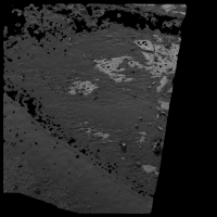
And here it is after removing the effects of lighting as described above:
The previously bright and dark slopes are now about the same brightness. The darker and lighter sides of some of the larger rocks can also be seen to have equalized to some extent. I put a limit on the zenith angle to avoid shadows turning white, and the results for rocks might be a little better if I used a less conservative cap. I didn't bother to account for scattering from the surface, and this would probably be improved if I did. The geometry data isn't perfect, so this method is only going to get you so far, but I thought it was neat that it works as well as it does, particularly considering someone who really has no idea what they're doing was able to code it with enough googling.  |
||
|
|
|
||
|
Apr 19 2016, 03:33 PM
Post
#506
|
|
|
Member Group: Members Posts: 244 Joined: 2-March 15 Member No.: 7408 |
I'm hoping someone here can explain this to me (or link me to something). I need optical depth for some of these equations I'm using for irradiance and whatnot. I've been just guessing and tweaking until now, but that's just not a sustainable workflow. In my attempts to figure out how to get optical depth, I quickly found out that this is MASTCAM's job. MASTCAM likes to stare at the Sun and until recently, I thought this was just for reference frame refinement or whatever, but even the rationale in the LBLs says it's to "Measure the optical depth of the atmosphere and constrain aerosol scattering properties". I tried to figure out how to calculate the optical depth from the MASTCAM data products, but I've finally, after fumbling and fiddling for hours on end, had to admit that I don't know what I'm doing and that the resources I've been able to find online just aren't enough to fill in the gaps in my knowledge in order to calculate the optical depth.
 I'd thought there would be a public record of calculated optical depths by sol or observation somewhere in PDS or on some other site, but I wasn't able to find one. I didn't search past any paywalls, so I guess it's possible that data exists somewhere for a fee. What I'm asking here is either... 1. Is there a public record somewhere that contains calculated optical depths for MSL by sol or observation or whatever? I found a chart in a paper that had some for the first few hundred sols, but that's not really going to be enough. or... 2. How can I calculate the optical depth from the MASTCAM data products labeled as being for measuring optical depth? Assume I already know how to get the solar zenith angle and the irradiance incident on the top of the atmosphere at the time of a given observation. Really, any help anyone can provide at all would be greatly appreciated; it may just be that I'm missing some detail that can get me going in the right direction. 
|
|
|
|
|
Apr 20 2016, 09:36 AM
Post
#507
|
|
|
Martian Photographer Group: Members Posts: 352 Joined: 3-March 05 Member No.: 183 |
There will be a freely available archive, I'm sure of that. But it is not there yet. Depending on the required accuracy, you wouldn't go far wrong by using the Opportunity results--that comparison has been made in a few conference presentations.
|
|
|
|
|
Apr 20 2016, 02:30 PM
Post
#508
|
|
|
Senior Member Group: Members Posts: 2511 Joined: 13-September 05 Member No.: 497 |
QUOTE (Herobrine @ Apr 19 2016, 07:33 AM) I need optical depth for some of these equations I'm using for irradiance and whatnot. You might consider trying to do what you're trying to do for the time period for which there are published optical depths. See, e.g., http://www.hou.usra.edu/meetings/8thmars2014/pdf/1338.pdf I expect you'll find that the optical depth measurements don't really solve your problem, but I could be wrong. -------------------- Disclaimer: This post is based on public information only. Any opinions are my own.
|
|
|
|
|
Apr 20 2016, 08:27 PM
Post
#509
|
|
|
Member Group: Members Posts: 244 Joined: 2-March 15 Member No.: 7408 |
QUOTE (Deimos @ Apr 20 2016, 04:36 AM) There will be a freely available archive, I'm sure of that. But it is not there yet. Depending on the required accuracy, you wouldn't go far wrong by using the Opportunity results--that comparison has been made in a few conference presentations. I'd considered using Viking data to make a seasonal profile of optical depth. I'm not sure why I didn't think to use Opportunity data instead since the latitudes are closer and it's the same time period. I'm not sure how close Opportunity data would get me, considering it's more than 1/4 of the way around the planet but, looking at the chart mcaplinger linked, they seem to stay very close, so if I can't figure out how to derive it from the MASTCAM observations, I might give that a try. Thanks.  QUOTE (mcaplinger @ Apr 20 2016, 09:30 AM) You might consider trying to do what you're trying to do for the time period for which there are published optical depths. See, e.g., http://www.hou.usra.edu/meetings/8thmars2014/pdf/1338.pdf I expect you'll find that the optical depth measurements don't really solve your problem, but I could be wrong. I'd considered using that particular chart and the MASTCAM data products that correspond to the data points to verify my numbers once I got to the point where I thought I was calculating it correctly. If I give up before figuring out how to calculate it, I'll probably use some combination of Opportunity data and that early MSL data. Thanks. I'm not quite sure what you mean about it not really solving my problem. My only problem at the moment is that I have to guess-and-check optical depth for each frame I'm working with. If I had the measured values, that would solve it. Maybe I should explain what it is I'm actually doing with the data at the moment. Prompted by yogi's question about calibrating brightness between images taken at different times of day, I modified the mesh generation stuff I was working on to see how easy it would be to address that issue by trying to derive albedo from NAVCAM images using the metadata and the radiometric and spatial data products in PDS. For example, take the following two NAVCAM frames, taken a few sols apart (shown here in a shared scale of absolute radiance):   (click for full-size) They were acquired when the Sun was respectively 11 and 55 degrees from the zenith, so the second frame exhibits substantially lower radiance than the first. Assuming an optical depth of 0.5 and a local mean albedo of 0.2, I use the metadata and the spatial (XYR and UVW, along with MXY for masking rover structure) data products to calculate the approximate total incident solar irradiation (direct + diffuse + ground) at each pixel on the surface for which spatial data was available (shown here in a shared scale of absolute irradiance):   (click for full-size) As expected, the surface in the second frame is receiving substantially less light than the first. Dividing the observed radiance by the calculated approximate total incident solar irradiance gives me the (scaled) albedo (shown here in a shared scale of albedo):   (click for full-size) The scaled albedo is approximate and rough, like the calculated incident irradiance, since the spatial data isn't perfect and we haven't accounted for shadows and small-scale occlusion of ambient light by surrounding surface geometry, among other things, but we weren't trying to perfectly extract albedo; we were trying to "calibrate the brightness" of the two scenes, and we've done that. Well, really, we've roughly removed shading due to lighting conditions, and only for the pixels that had associated spatial data. Edit: Added clarification that the result of the division at the end yields a scaled albedo (not in the 0-1 range). |
|
|
|
|
Apr 20 2016, 08:35 PM
Post
#510
|
|
|
Administrator Group: Admin Posts: 5172 Joined: 4-August 05 From: Pasadena, CA, USA, Earth Member No.: 454 |
I am seriously impressed by how closely the brightness of your two output images match, and look forward to your continued work on this!
(I love it when physics works.) -------------------- My website - My Patreon - @elakdawalla on Twitter - Please support unmannedspaceflight.com by donating here.
|
|
|
|
|

|
Lo-Fi Version | Time is now: 18th April 2024 - 02:57 AM |
|
RULES AND GUIDELINES Please read the Forum Rules and Guidelines before posting. IMAGE COPYRIGHT |
OPINIONS AND MODERATION Opinions expressed on UnmannedSpaceflight.com are those of the individual posters and do not necessarily reflect the opinions of UnmannedSpaceflight.com or The Planetary Society. The all-volunteer UnmannedSpaceflight.com moderation team is wholly independent of The Planetary Society. The Planetary Society has no influence over decisions made by the UnmannedSpaceflight.com moderators. |
SUPPORT THE FORUM Unmannedspaceflight.com is funded by the Planetary Society. Please consider supporting our work and many other projects by donating to the Society or becoming a member. |
|