Range Finding - Parallax Calculations |

  |
Range Finding - Parallax Calculations |
 Dec 3 2005, 02:46 PM Dec 3 2005, 02:46 PM
Post
#1
|
|
 Dublin Correspondent  Group: Admin Posts: 1799 Joined: 28-March 05 From: Celbridge, Ireland Member No.: 220 |
Just setting this up as a topic.
Rodolfo (RNeuhaus) has pointed out that he gets hard to interpret results when using Joe Knapp's online Parallax Calculator. I don't know the formulas behind this calculator but have been trying to work out my own. Taking (for now) that the geometries are as follows: Pancam, 16deg FOV, 300mm separation between L and R and a 1deg toe in. Navcam, 45deg FOV 200mm separation between L and R and no toe in. Parallax formula - Distance to object=half the Camera Separation/Tan angle between the point in the L+R images. (I don't think this is 100% correct for parallel cameras but it should be good to a close first approximation provided things aren't too close). Sticking with the Navcam which doesn't have any toe in my gut feel for things is that distant objects should be affected less by parallax. So taking Joe Knapps sample calculation for Navcam. Left Camera 512 pixels, right camera 500 pixels. Separation is 12 pixels so the parallax angle is 12 * (45deg/1024pixels) = 0.527344 degrees. The distance should then be (100mm/tan(0.527344 deg). That gives me 108m. Joe Knapps calculator gives me 20.3m. The Pancam is a bit trickier because of the toe in angle, I need to think a bit more about whether my default assumption that it can be compensated for by simply subtracting 64 pixels from the right image position is valid or not. Anyway - something is amiss in either my numbers or Joe Knapp's calculator. Anyone out there able to throw some light on this. |
 |
 
|
|
Dec 5 2005, 03:47 PM
Post
#2
|
|
|
Senior Member Group: Members Posts: 1636 Joined: 9-May 05 From: Lima, Peru Member No.: 385 |
Good to hear from you. I have already written a note to the PANCAM Parallex calculator's author on last Friday. Up to know, there is no news from him.
About a manual measurement, the document (Bell's one) says that the PANCAM resolution is designed specially up to 100 meters which is the designated range of roving per day. Its resolution is about 2.8 cms per pixel at a range of 100 meters. This leads me to think that the distance of every pixel is not lineal but the closer range, the distance would be smaller than 2.8 cms per pixel and the average would be at 50 meters with 2.8 cms per pixel and at 100 meters would be smaller than 2.8 cms / pixel. Isn't that right? On the other hand, I remember that someone was able to calculate the distance between the Spirit to the slope obstacles of Hasking Ridge with some kind of software Pancam Parallax. Which ones is that? Rodolfo |
|
|
|
|
Dec 5 2005, 07:53 PM
Post
#3
|
|
|
Dublin Correspondent Group: Admin Posts: 1799 Joined: 28-March 05 From: Celbridge, Ireland Member No.: 220 |
Rodolfo,
The author (Joe Knapp) posts here as jmknapp I think. It might be worth sending him a PM. I'm still getting the impression that you don't understand the fundamental geometry of the set up. If I'm mistaken, apologies but I think I need to step through this carefully to be certain you understand the basic principles. Each camera covers a fixed field of view. That means that if you were to draw a triangle looking down on the scene then the angle between the left hand side of the image, the camera andthe right hand side of the image is 16deg for the Pancams and 45deg for the NavCam. So the field of view (from extreme left to extreme right) of any of these images always has the same angular distance. This means that as you move further away from the camera the physical dimension covered by an individual pixel gets bigger. The exact physical dimensions (D) of a Pancam pixel at a given distance (X) is represented by the following: D=X*(tan(8)/512 See this web page for a useful diagram and an explanation of this formula. We use half the FOV and half the number of pixels of a full image so we can work with the simple right handed triangle. So the pixels on a Pancam image, like every other camera with a 16deg FOV taking a 1024 pixel image have the following dimensions (in cm): Range(m) Pixel size 1 -----------0.027449382 5 -----------0.137246909 10 ----------0.274493818 20 ----------0.548987636 50 ----------1.372469089 70 ----------1.921456724 100 ---------2.744938178 I have to reiterate that are fundamentally related to the FOV of the camera and they apply equally to any camera anywhere which has a 16deg FOV. The numbers for the Navcam are different since it has a wider FOV. The calculations for finding the specific range of an object uses the same basic idea but in reverse (more or less). From a pair of left and right images you can read off the parallax angle of a feature by counting how many pixels it appears to move between the two images since each pixel always corresponds to a fixed angle (16/1024==0.015625deg for Pancam). Since you also know the distance between the two cameras you are once again dealing with a triangle where you know all the angles and have the length of one side. From that you can work out the missing bits, in particular the range to the object. My back of the envelope drawings of the parallel situation (for the Navcam) lead me to believe that the range should be closely approximated by: Range=0.1m/Tan(No of Pixels * 0.043945deg) (Navcam) Range=0.15m/Tan(No of Pixels * 0.015625deg) (Pancam) I'd welcome some comments on this because I suspect that this is not completely accurate but I'm pretty sure that even if that is the case the error is going to be small provided the range is above a couple of metres. The Pancam case is complicated by the 1 deg toe but I think that simply adding 64 pixels (1024/16 == no of pixels in 1 deg for a Pancam image) to the measured measured value for the right hand image should be sufficient. |
|
|
|
|
Dec 5 2005, 11:40 PM
Post
#4
|
|
|
Junior Member Group: Members Posts: 90 Joined: 13-January 05 Member No.: 143 |
QUOTE (helvick @ Dec 3 2005, 06:46 AM) Taking (for now) that the geometries are as follows: Pancam, 16deg FOV, 300mm separation between L and R and a 1deg toe in. Navcam, 45deg FOV 200mm separation between L and R and no toe in. Parallax formula - Distance to object=half the Camera Separation/Tan angle between the point in the L+R images. (I don't think this is 100% correct for parallel cameras but it should be good to a close first approximation provided things aren't too close). Sticking with the Navcam which doesn't have any toe in my gut feel for things is that distant objects should be affected less by parallax. So taking Joe Knapps sample calculation for Navcam. Left Camera 512 pixels, right camera 500 pixels. Separation is 12 pixels so the parallax angle is 12 * (45deg/1024pixels) = 0.527344 degrees. The distance should then be (100mm/tan(0.527344 deg). That gives me 108m. Joe Knapps calculator gives me 20.3m.  I think you're off by a factor of two in your formula and a factor of 10 in your calculator. I get 200mm/tan(0.527344 deg) = 21.7 m. |
|
|
|
|
Dec 6 2005, 03:17 AM
Post
#5
|
|
|
Senior Member Group: Members Posts: 1636 Joined: 9-May 05 From: Lima, Peru Member No.: 385 |
Helvick, Thanks for the response. However I still did not grasp fully the understanding of MER Stereo Parallax Calculator and below I have some questions to clarify.
About the formula: 100mm/tan(0.527344 deg). What is 100 mm (milimiter)? Is the distance of what are you saying. Tan(@) = opposite/adjacent. --> adjacent (distance) = tan (@) / opposite For the NAVCAM, according to the material you showed me about the formule: View has an angle: @ Half view of the angle is: @/2 The distance of the angle is: l Half distance of the angle is: l/2 The adjacent distance is: d (vertical height) Then the formule: tan (@/2) = (l/2)/d to know the distance from the viewer: d = (tan(@/2))/(l/2) Let suppose that a point of interest in the picture: a stone: Left navcam: 580 pixels (GIMP tool measurement) and the Right navcam: 590 pixels: According to the Parallalx calculator: object distance: 8.92 m, one-pixel error: 0.037 m object dimension: 0.2 cm. According to the formule: The separation distance is: 590-580= 10 pixels. @ angle is: (10 pixels*45 degree)/1024 pixels @ = 0.439453 distance = "opposite side, not known, how to obtain it?" x tan(0.439453). I guess that the opposite side must be always of 100 meters? Rodolfo P.D.jamescanvin has talked about the measurement of distances with parallax calculator in the topic: Haskin Ridge, how did he measured it? See at the post |
|
|
|
|
Dec 6 2005, 04:24 AM
Post
#6
|
|
 Senior Member Group: Moderator Posts: 2262 Joined: 9-February 04 From: Melbourne - Oz Member No.: 16 |
Just jumping in as I'm mentioned:
QUOTE (RNeuhaus @ Dec 6 2005, 02:17 PM) About the formula: 100mm/tan(0.527344 deg). What is 100 mm (milimiter)? Is the distance of what are you saying. As mars_armer pointed out that should be 200mm which is the distance between the navcams. I guess helvick new that and was using half the seperation distance to make a true right angled triangle (his mistake was then not to then divide the angle by two!) QUOTE (RNeuhaus @ Dec 6 2005, 02:17 PM) Let suppose that a point of interest in the picture: a stone: Left navcam: 580 pixels (GIMP tool measurement) and the Right navcam: 590 pixels: According to the Paralalx calculator: object distance: 8.92 m, one-pixel error: 0.037 m object dimension: 0.2 cm. According to the formule: The separation distance is: 590-580= 10 pixels. @ angle is: (10 pixels*45 degree)/1024 pixels @ = 0.439453 distance = "opposite side, not known, how to obtain it?" x tan(0.439453). I guess that the opposite side must be always of 100 meters? as above: opposite side = distance between cameras = 200mm. Which gives about 26.0m using 0.2m/tan(0.439453) Why the discrepency with your value of 8.92m from the calculator? Well, it looks like you were using the pancam setting! When I put in those values I get: object distance: 24.4 m, one-pixel error: 1.234 m All seems consistent to me.  QUOTE (RNeuhaus @ Dec 6 2005, 02:17 PM) P.D.jamescanvin has talked about the measurement of distances with parallax calculator in the topic: Haskin Ridge, how did he measured it? See at the post Just using the Parallax Calculator like above, nothing more. Measure the pixel positions of the same object in the L & R frames and feed the numbers to tthe program. James. -------------------- |
|
|
|
|
Dec 6 2005, 07:40 AM
Post
#7
|
|
|
Senior Member Group: Moderator Posts: 4279 Joined: 19-April 05 From: .br at .es Member No.: 253 |
Rodolfo, just an additional reminder:
You will see that the farther the distance to a feature, bigger is the "one-pixel" error. When measuring a range via parallax you must be *exact* (as much as possible) with the pixel positions for a feature on the L and R images. |
|
|
|
|
Dec 6 2005, 10:31 AM
Post
#8
|
|
|
Dublin Correspondent Group: Admin Posts: 1799 Joined: 28-March 05 From: Celbridge, Ireland Member No.: 220 |
QUOTE (jamescanvin @ Dec 6 2005, 05:24 AM) Just jumping in as I'm mentioned: As mars_armer pointed out that should be 200mm which is the distance between the navcams. I guess helvick new that and was using half the seperation distance to make a true right angled triangle (his mistake was then not to then divide the angle by two!) Err, yes. Wasn't paying attention to myself there. Apologies for my confusion, I appear to have had enough coffee by the time I made my later post and didn't repeat the error. I still seem to have some problems with the parallax calculator site on my main machine - it appears to cache results strangely which another reason why I was getting confused. Apart from forgetting trig 101 that is. Oh well. I'm still a bit confused though because the Parallax calculator page doesn't generally agree with my numbers. I found Joe Knapps original post regarding the Pancams - it seems that I misunderstood the meaning of the "~1 deg" toe in, again not thinking clearly, both cameras have the toe in angle so the observed parallax must be adjusted by twice the amount I referred to (~64 pixels based on an 1deg toe in). There's more to it than that though: QUOTE Based on the left and right images, there's a parallax of 92 pixels at the rock. The distance equation for Opportunity's pancam is: D = 1071/(130 - N) D = 1071/(130 - 92) = 28.2 meters The width of the rock is 54 pixels. At 0.28 mrad/pixel (pancam spec) that's 15 mrad. Width then would be 28.2*0.015 = 0.42 m. The width of the bounce mark is 223 pixels or 1.8 m. Interesting. |
|
|
|
|
Dec 6 2005, 11:57 AM
Post
#9
|
|
 Senior Member Group: Members Posts: 1465 Joined: 9-February 04 From: Columbus OH USA Member No.: 13 |
My parallax calculator could sure use some improvements. It's based on a simplified geometric model and neglects complications like actual (vs. designed) pointing and toe-in of the cameras, non-linear optical effects, etc. There may be some operational issues too like the "strange caching of results" mentioned above.
More recently I have found the NAIF file speciying the camera geometry which makes some parameters clearer, but some less so as I don't have any experience with the CAHVOR model the experts use to define the camera geometry. The latest "frames definition kernel" for MER2 is at: ftp://naif.jpl.nasa.gov/pub/naif/MER/kernels/fk/mer2_v09.tf This is a text file that can be opened in an editor. It has both text descriptions of the geometry and also parameter/value pairs. Here is one snippet: QUOTE Nominal PMA [primary mast assembly] camera orientations are such that NAVCAM left and right boresights are parallel to each other and the PMA head +X axis, while the PANCAM left and right boresights "toe"ed in by 1 degree toward the PMA head +X axis. In order align PMA head frame with the camera frames in this nominal orientation, it has to be rotated by +90 degrees about Y and then about X by non-zero "toe"-ins for the PANCAM (-1 degree for the left camera and +1 degree for the right camera) and by zero "toe"-ins for NAVCAM, and finally by -90 degrees about Z (to line up Y axis with the vertical direction.) The following sets of keywords should be included into the frame definitions to provide this nominal orientation (provided for reference only): TKFRAME_-254121_AXES = ( 2, 1, 3 ) TKFRAME_-254121_ANGLES = ( -90.000, 1.000, 90.000 ) ...etc. So that makes it fairly clear that both boresights are toed-in, for a total 2 degrees (1 degree left and right) by design. The PANCAM X-axis is the axis looking out from the pancams (e.g., towards the horizon). The Y-axis is the left/right direction and the Z-axis is the vertical. The SPICE kernel developers have taken ASCII-art to a wonderful level, and here is their diagram of the PANCAM frame: QUOTE UHF /\ HGA \/ PMA .--. # || / \ # || | | # || \ /=. # || `--' || # || Rover ======================= (deployed) | =o=. | | .' Yr `.__|o====o .===o=== o------> Xr \\ .-. .|. `.-. ##o### | o | | | | | o | `-' `|' `-' IDD V Zr Clear now?  The 1-degree toe-in per camera is by design, but evidently, if I read the frames kernel right, reality is quite a bit different. For the left PANCAM we have: QUOTE The actual MER-2_PANCAM_LEFT_F1 frame orientation provided in the frame definition below was computed using the CAHVOR(E) camera model file, 'MER_CAL_176_SN_104_F_1.cahvor'. According to this model the reference frame, MER-2_PMA_HEAD, can be transformed into the camera frame, MER-2_PANCAM_LEFT_F1, by the following sequence of rotations: first by 90.05088205 degrees about Y, then by -0.65914547 degrees about X, and finally by -90.31522256 degrees about Z. The frame definition below contains the opposite of this transformation because Euler angles specified in it define rotations from the "destination" frame to the "reference" frame. \begindata FRAME_MER-2_PANCAM_LEFT_F1 = -254121 FRAME_-254121_NAME = 'MER-2_PANCAM_LEFT_F1' FRAME_-254121_CLASS = 4 FRAME_-254121_CLASS_ID = -254121 FRAME_-254121_CENTER = -254 TKFRAME_-254121_RELATIVE = 'MER-2_PMA_HEAD' TKFRAME_-254121_SPEC = 'ANGLES' TKFRAME_-254121_UNITS = 'DEGREES' TKFRAME_-254121_AXES = ( 2, 1, 3 ) TKFRAME_-254121_ANGLES = ( -90.051, 0.659, 90.315 ) \begintext So the toe-in rotation about the X-axis is only 0.58 degree rather than 1.0 degree, moreover the are fractional-degree deviations of the Y and Z axes. Then there are the CAHVOR complications. The CAHVOR model is specified in the instrument kernels left PANCAM instrument kernel right PANCAM instrument kernel At this point I throw up my hands! -------------------- |
|
|
|
|
Feb 11 2006, 04:02 PM
Post
#10
|
|
 Member Group: Members Posts: 656 Joined: 20-April 05 From: League City, Texas Member No.: 285 |
QUOTE (jmknapp @ Dec 6 2005, 06:57 AM) ... The 1-degree toe-in per camera is by design, but evidently, if I read the frames kernel right, reality is quite a bit different. For the left PANCAM we have: So the toe-in rotation about the X-axis is only 0.58 degree rather than 1.0 degree, moreover the are fractional-degree deviations of the Y and Z axes. Then there are the CAHVOR complications. The CAHVOR model is specified in the instrument kernels ... At this point I throw up my hands! Perhaps I can shed a little light on this. I pulled-up the ftp://naif.jpl.nasa.gov/pub/naif/MER/kernels/fk/mer2_v09.tf file and looked at the pancam reference frame orientations: PancamLeft TKFRAME_-254128_AXES = ( 2, 1, 3 ) TKFRAME_-254128_ANGLES = ( -90.051, 0.659, 90.315 ) PancamRight TKFRAME_-254131_AXES = ( 2, 1, 3 ) TKFRAME_-254131_ANGLES = ( -89.946, -1.376, 90.400 ) I worked-out the combined rotations, rotating (for PancamL) as specified first -90.051 degrees about the Y axis, then 0.659 degrees about the X axis, and 90.315 degrees about the Z axis (in that order), then did the same for PancamR, and worked-out the relative orientation between them (I did all this using quaternions, as they're easier and more accurate than 3X3 matrices). The net result is that the relative orientation between the left and right pancams is 2.039451 degrees about the unit axis vector (-0.045257,-0.998119,0.041349). Not exactly the expected 2 degrees, but darn close. Incidentally, in the CAHVOR data from the instrument kernels is a unit referred to as the CAHVOR_QUAT. From this quaternion I extract a rotation of 181.908954 degrees about axis vector (0.046757,0.000780,0.998906), which is surprisingly close to 2 degrees as well (if you subtract off 180 degrees). However both cameras have EXACTLY the same CAHVOR_QUAT value, so I'm not clear on what this refers to. I pulled-up a paper discussing the CAHVOR camera model but it didn't give any mention to CAHVOR_QUAT, so I don't know what rotation that parameter refers to. I'm still not sure how to go from this to photogrammetry, or I'd whip-up some software. |
|
|
|
|
Feb 14 2006, 09:49 PM
Post
#11
|
|
|
Senior Member Group: Members Posts: 1465 Joined: 9-February 04 From: Columbus OH USA Member No.: 13 |
Interesting that taking all the rotations into account gives the correct figure of 2 degrees. Kudos for the quaternion math!
-------------------- |
|
|
|
|
Mar 2 2006, 01:51 AM
Post
#12
|
||
|
Member Group: Members Posts: 656 Joined: 20-April 05 From: League City, Texas Member No.: 285 |
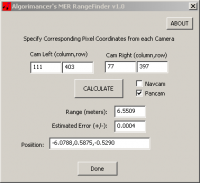
I have just completed a new 3D MER RangeFinder:
http://www.clarkandersen.com/RangeFinder.htm Screenshot:
The new RangeFinder uses the CAHVOR camera models for the pancams and navcams, takes 2D coordinates from the image pairs, and uses photogrammetry to calculate a 3D distance, error, and even the coordinates of the point, albeit in the camera reference frame. If there is sufficient interest I may add a batch processing utility to it at some point. |
|
|
|
|
|
|
Mar 2 2006, 12:21 PM
Post
#13
|
|
|
Senior Member Group: Members Posts: 1465 Joined: 9-February 04 From: Columbus OH USA Member No.: 13 |
QUOTE (algorimancer @ Mar 1 2006, 08:51 PM) I have just completed a new 3D MER RangeFinder: Very nice & a lot of work I bet! I notice it works out to 100m or so--my calculator really went haywire at the longer ranges. -------------------- |
|
|
|
|
Mar 2 2006, 01:31 PM
Post
#14
|
|
|
Member Group: Members Posts: 656 Joined: 20-April 05 From: League City, Texas Member No.: 285 |
QUOTE (jmknapp @ Mar 2 2006, 06:21 AM) Very nice & a lot of work I bet! I notice it works out to 100m or so--my calculator really went haywire at the longer ranges. Thank you I was (and am) rather surprised myself at the apparent accuracy, which I can only attribute to the good job the JPL folks did of calibrating the cameras. Since I'm using the Spirit calibration, I'm not sure how well it will compare when used on Opportunity, but the camera model parameters seem pretty close. There is also additional calibration data for each filter of the pancams, but no significant difference between them. I'm debating with myself the notion of integrating all the calibration data for all filters of both rovers (relatively easy to do, but not as clean an interface). At the same time, I'd like to release the source code but will have to investigate some copyright issues first; handling the vector ops with the Boost library would be an easy step in that direction. I'm leaning towards providing a command line interface and a class library release at some point, and it should easily generalize to any rover/lander/etceteras with a stereo pair of cameras and corresponding CAHVOR calibration.A surprising amount of the work involved in creating this application was simply tracking down the details of the CAHVOR camera model; the vast majority of the relevant papers & web pages were more concerned with generating the model parameters than using them. Frustratingly, rather a lot of the needed papers (found via Google) were bad links to the JPL robotics site; seems like they've decided to isolate a lot of material from the web lately 
|
|
|
|
|
Mar 2 2006, 01:50 PM
Post
#15
|
|
|
Founder Group: Chairman Posts: 14432 Joined: 8-February 04 Member No.: 1 |
I know JB's out the office at the moment, but I'm sure he'd help you out if you needed more info - his email addy is easily googlable.
Doug |
|
|
|
|

|
Lo-Fi Version | Time is now: 29th April 2024 - 03:03 AM |
|
RULES AND GUIDELINES Please read the Forum Rules and Guidelines before posting. IMAGE COPYRIGHT |
OPINIONS AND MODERATION Opinions expressed on UnmannedSpaceflight.com are those of the individual posters and do not necessarily reflect the opinions of UnmannedSpaceflight.com or The Planetary Society. The all-volunteer UnmannedSpaceflight.com moderation team is wholly independent of The Planetary Society. The Planetary Society has no influence over decisions made by the UnmannedSpaceflight.com moderators. |
SUPPORT THE FORUM Unmannedspaceflight.com is funded by the Planetary Society. Please consider supporting our work and many other projects by donating to the Society or becoming a member. |
|