Juno PDS data |

  |
Juno PDS data |
 Mar 6 2018, 03:06 AM Mar 6 2018, 03:06 AM
Post
#91
|
|
|
Senior Member  Group: Members Posts: 2511 Joined: 13-September 05 Member No.: 497 |
QUOTE (Bjorn Jonsson @ Mar 5 2018, 03:22 PM)  Regarding C kernels, I always use orientation data from the C kernel for every R/G/B set of framelets (typically 25-40 sets per image) and I also do this for the spacecraft position. This is the only method I would have imagined would be adequate without a lot of manual tweaking, and it's the way the MSSS processing works. As far as I can tell from reading Brian's Mathematica code (I don't have Mathematica and the raw ASCII is not the easiest thing to read) he isn't using the C kernel data and he only uses the spacecraft position at the beginning of imaging, but his results are very good so perhaps this doesn't matter in most cases. As for the expected errors, using our parameters the position error of the galilean satellites on orbit 1 had standard deviations of about 1 in X and about 2.8 in Y. I attribute the higher Y error to timing slop, but we could have residual geometric distortion error because the satellites were probably near the optic axis where distortions are lower. For obscure reasons, our own standard processing isn't using our updated parameters yet, though. -------------------- Disclaimer: This post is based on public information only. Any opinions are my own.
|
 |
 
|
|
Mar 6 2018, 04:03 AM
Post
#92
|
|
|
Member Group: Members Posts: 406 Joined: 18-September 17 Member No.: 8250 |
QUOTE (mcaplinger @ Mar 5 2018, 07:06 PM) .. As far as I can tell from reading Brian's Mathematica code (I don't have Mathematica and the raw ASCII is not the easiest thing to read) Ewww (that stuff isn't pretty). If you download and install the much too large CDF Player you'll be able to view the document properly formatted. (Hover over the right side to show section expansion controls.) QUOTE he isn't using the C kernel data and he only uses the spacecraft position at the beginning of imaging, but his results are very good so perhaps this doesn't matter in most cases. My simple pipeline doesn't do map projection, so it doesn't use position. The only thing it uses from SPICE is Angular Velocity Magnitude for the spin rate. |
|
|
|
|
Mar 6 2018, 05:03 AM
Post
#93
|
|
|
Senior Member Group: Members Posts: 2346 Joined: 7-December 12 Member No.: 6780 |
For my drafts, like these for PJ09, I don't use SPICE data, except data similar to those in the ik. It's a fixed processing pipeline that just uses the PJ number as a PJ specific parameter in order to know which directory to process. The other parameters are so similar between perijoves, that only higher quality requirements need a specific calibration.
The principle is similar to Brian's. Calibration runs are optional and based merely on distant Jupiter images. This simplified processing method ends, where data about solar illumination, other 3D data, or accurate alignment of close-up features is required. Then SPICE trajectory and pointing data simplify processing considerably. For New Horizons, I made some experiments with infering orbital trajectory data, and mass estimates of Pluto and Charon from images. But that's rather complicated, time consuming, and not necessarily very accurate. Especially Jupiter with its oblate shape would add another challenge. That said, Brian accomplished an important milestone in understanding JunoCam's way to take images. This understanding is a value for itself, since it prepares you for the next level of challenges. And beyond some point, when you'll explore unknown territory, nobody will be able to give you useful help anymore, and you'll need to rely on your own acquired capabilities. |
|
|
|
|
Mar 18 2018, 04:38 PM
Post
#94
|
|
|
Member Group: Members Posts: 406 Joined: 18-September 17 Member No.: 8250 |
Mike, Can you release to public domain the photo of the sensor and filters that is Figure 12 in "Junocam: Junos Outreach Camera"?
If not, I'll remove the copy embedded in the comments of my pipeline in the next release. |
|
|
|
|
Mar 23 2018, 06:11 PM
Post
#95
|
|
|
Senior Member Group: Members Posts: 2511 Joined: 13-September 05 Member No.: 497 |
QUOTE (Brian Swift @ Mar 18 2018, 08:38 AM) Mike, Can you release to public domain the photo of the sensor and filters that is Figure 12 in "Junocam: Junos Outreach Camera"? The paper is open access: "This article is distributed under the terms of the Creative Commons Attribution License which permits any use, distribution, and reproduction in any medium, provided the original author(s) and the source are credited." -------------------- Disclaimer: This post is based on public information only. Any opinions are my own.
|
|
|
|
|
Mar 24 2018, 12:44 AM
Post
#96
|
|
|
Member Group: Members Posts: 406 Joined: 18-September 17 Member No.: 8250 |
QUOTE (mcaplinger @ Mar 23 2018, 11:11 AM) The paper is open access... Thanks Mike. Can you make an original resolution version of the image available. Also, do you know how accurate the .001s adjusted INTERFRAME_DELAY is? I've only seen the values of the INTERFRAME_DELAY and adjustment given to 1ms of precision, but I believe the accuracy is significantly better than that. |
|
|
|
|
Mar 24 2018, 01:22 AM
Post
#97
|
|
|
Senior Member Group: Members Posts: 2511 Joined: 13-September 05 Member No.: 497 |
QUOTE (Brian Swift @ Mar 23 2018, 04:44 PM) Thanks Mike. Can you make an original resolution version of the image available. I guess, but it's just eye candy without practical benefit, right? QUOTE Also, do you know how accurate the .001s adjusted INTERFRAME_DELAY is? I've only seen the values of the INTERFRAME_DELAY and adjustment given to 1ms of precision, but I believe the accuracy is significantly better than that. If I understand your question, it's not. The delay is commanded in multiples of 20000 cycles of a 20 MHz clock, and the 1 msec offset was caused by an off-by-one misunderstanding in the commanding of the counter. So to the accuracy of the clock oscillator, which we don't know anything about other than it's within 20 ppm or so, the adjustment really is 1.0000 msec. It's probably slightly different, but we have no internal way of assessing that. -------------------- Disclaimer: This post is based on public information only. Any opinions are my own.
|
|
|
|
|
Mar 24 2018, 05:21 AM
Post
#98
|
|
|
Member Group: Members Posts: 406 Joined: 18-September 17 Member No.: 8250 |
QUOTE (mcaplinger @ Mar 23 2018, 05:22 PM) I guess, but it's just eye candy without practical benefit, right? I'm thinking of creating a diagram out of it by correcting the perspective and overlaying the filter readout ranges. QUOTE If I understand your question, it's not. The delay is commanded in multiples of 20000 cycles of a 20 MHz clock, and the 1 msec offset was caused by an off-by-one misunderstanding in the commanding of the counter. So to the accuracy of the clock oscillator, which we don't know anything about other than it's within 20 ppm or so, the adjustment really is 1.0000 msec. It's probably slightly different, but we have no internal way of assessing that. The above is exactly what I was curious about. My modeling is currently estimating a value of 0.001032 sec for the adjustment. |
|
|
|
|
Mar 24 2018, 03:55 PM
Post
#99
|
|
|
Senior Member Group: Members Posts: 2511 Joined: 13-September 05 Member No.: 497 |
QUOTE (Brian Swift @ Mar 23 2018, 09:21 PM) My modeling is currently estimating a value of 0.001032 sec for the adjustment. Well, I can't say that's impossible, but it's about 30x larger than the largest clock error I would expect given the specification of the clock oscillator. An error in interframe delay and/or spin rate would lead to increasing downspin errors over the course of a full image acquisition. Our star and galilean satellite imaging analyses don't show those to my eye (if I'm doing the math right the error you state would build up to 82*0.000032*371 or almost a second of error over a full spin, which would be easily noticable) but I don't claim to know for sure. -------------------- Disclaimer: This post is based on public information only. Any opinions are my own.
|
|
|
|
|
Mar 26 2018, 02:16 AM
Post
#100
|
|
|
Senior Member Group: Members Posts: 2346 Joined: 7-December 12 Member No.: 6780 |
82 * 32µs = 2.624ms. This would be a little less than 1 pixel. You won't probably be much more accurate on the basis of stars when working with a single swath.
But a relative error of 32µs / 371ms = 8.6e-5 would add up to about 1 sec within a little more than three hours. The clock is certainly more accurate by orders of magnitude. So, the error is much more likely in the geometrical camera calibration than in the clock. |
|
|
|
|
Mar 26 2018, 11:27 PM
Post
#101
|
|
 IMG to PNG GOD Group: Moderator Posts: 2250 Joined: 19-February 04 From: Near fire and ice Member No.: 38 |
The START_TIME value is also not accurate and this can be of significance. From the juno_junocam_v02.ti kernel:
QUOTE We have found that there is a fixed bias of 61.88 msec in the start time with a possible jitter of order 20 msec relative to the reported value...
|
|
|
|
|
Apr 7 2018, 01:43 AM
Post
#102
|
|
|
Member Group: Members Posts: 406 Joined: 18-September 17 Member No.: 8250 |
Juno28g, a JunoCam raw processing pipeline implemented in Mathematica has been updated. It is available under permissive open source license at https://github.com/BrianSwift/JunoCam
Changes:
|
|
|
|
|
Apr 7 2018, 10:19 AM
Post
#103
|
|
|
Member Group: Members Posts: 923 Joined: 10-November 15 Member No.: 7837 |
Here is my first pass using Brian's updated pipeline. I can confirm memory burps when upscaling.
 PJ12_100  -------------------- |
|
|
|
|
Apr 7 2018, 06:10 PM
Post
#104
|
|
|
Member Group: Members Posts: 406 Joined: 18-September 17 Member No.: 8250 |
QUOTE (Sean @ Apr 7 2018, 03:19 AM) Here is my first pass using Brian's updated pipeline. I can confirm memory burps when upscaling. Bit of a hack workaround for memory issues is to process a subset of frames with the frameRangeToProcess parameter, which is what I used for processing the Io full spin images at 90 pix/deg. |
|
|
|
|
Apr 10 2018, 05:57 PM
Post
#105
|
||||
|
Member Group: Members Posts: 406 Joined: 18-September 17 Member No.: 8250 |
Juno24u, a JunoCam camera modeling Mathematica notebook, is available under permissive open source license at https://github.com/BrianSwift/JunoCam
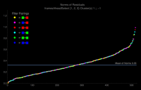
This notebook produces the lens parameters used in the Juno28g raw processing pipeline. From 29 CruisePhase and Oribit_00 data takes, 519 point source correspondences are automatically identified. Modeling optimizes lens parameter to minimize mean of distances between paired points forward-transformed to equirectangular coordinates. Various plots of residuals are produced to help evaluate the model and attempt to identify systematic modeling deficiencies. This is a plot residual distances (in pixels) between pairs of forward-transformed points
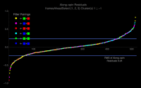
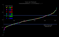
These two plots show residuals in the Along-Spin and Cross-Spin directions.
The notebook contains many more plots (with tooltips for each point). These are viewable when the notebook is opened with Wolfram CDF Player available from https://www.wolfram.com/cdf-player/ A CSV table of point correspondences is produced for anyone else building a JunoCam camera model. This table is also available at https://github.com/BrianSwift/JunoCam Additionally, PDFs annotating raw files are produced in which point sources used in modeling are circled and neighboring values of flattened and raw data are displayed. A rasterized greyscale version of an annotated raw calibration file is available at https://www.missionjuno.swri.edu/junocam/processing?id=4468 When this data is input to a JunoCam raw processing pipeline, the resulting image can help evaluate how well the pipeline's lens/camera model aligns Red, Green, and Blue framelets. The output produced by the current Juno24g pipeline is available at https://www.missionjuno.swri.edu/junocam/processing?id=4469 |
|||
|
|
|
|||
|

|
Lo-Fi Version | Time is now: 25th April 2024 - 07:50 AM |
|
RULES AND GUIDELINES Please read the Forum Rules and Guidelines before posting. IMAGE COPYRIGHT |
OPINIONS AND MODERATION Opinions expressed on UnmannedSpaceflight.com are those of the individual posters and do not necessarily reflect the opinions of UnmannedSpaceflight.com or The Planetary Society. The all-volunteer UnmannedSpaceflight.com moderation team is wholly independent of The Planetary Society. The Planetary Society has no influence over decisions made by the UnmannedSpaceflight.com moderators. |
SUPPORT THE FORUM Unmannedspaceflight.com is funded by the Planetary Society. Please consider supporting our work and many other projects by donating to the Society or becoming a member. |
|