Discussion of stray light in Juno Earth flyby images |

  |
Discussion of stray light in Juno Earth flyby images |
 Jan 4 2016, 07:20 PM Jan 4 2016, 07:20 PM
Post
#16
|
|
|
Senior Member  Group: Members Posts: 2510 Joined: 13-September 05 Member No.: 497 |
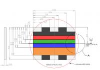
QUOTE (Gerald @ Jan 4 2016, 10:14 AM)  As described in the article, I've applied methods related to the Newton method to fit peaks into the EFB03 data. Keep in mind that EFB03 was taken in a mode that is unlikely to be duplicated for Jupiter observations (lots of TDI in a visible channel). We will probably only use a lot of TDI for the CH4 channel. In the diagram you show above of the CFA, be aware that there is a light shield between the top of the CCD and the back of the optics with an aperture nominally 0.231x0.473 inches centered on the center of the sensor. This is intended to block stray light paths from the sensor bond wires and metallization on the sensor package, though there could be some misalignment and some small paths could still exist. Mods: it might make sense to create a subforum for this material, much as was done with the MSL discussion of technical details about the cameras. -------------------- Disclaimer: This post is based on public information only. Any opinions are my own.
|
 |
 
|
|
Jan 5 2016, 01:24 PM
Post
#17
|
|
|
Senior Member Group: Members Posts: 2346 Joined: 7-December 12 Member No.: 6780 |
Thanks a lot, that's helpful information.
Provided the light shield is centered horizontally, but displaced vertically, such that the CH4 filter and the red filter are fully illuminated, this would explain the superposition of two ghosts below the primary image of the target object, and the presence of only one ghost above the primary image. The three bright rectangular areas next to the CH4 filter may add the sharp ghost below the primary image. In contrast, the corresponding bright rectangular areas near the red filters are covered completely by the light shield. The light shield itself might add the blurred ghost below and the ghost above the primary image. Thus far I found out, that (one of) the reflecting feature(s) adding the ghost above the primary image should be close to the lower end of the red filter. The blue filter appears to be shadowed from some stray light in a zone next to the CH4 filter. But I couldn't yet decypher, whether that's a side effect by design to protect the CH4 filter from stray light, or whether the CH4 filter is thicker than the blue filter, and casts a shadow. There is a large number of possibly relevant detail about the camera, but probably only a small fraction of which will turn out to be actually relevant for the calibration of the images. I presume, that a detailed plan of the geometry of all surfaces possibly in contact with non-negligible light eventually reaching the sensors together with BDRF data (including anti-reflective coatings), and the refractive indices of the translucent materials would be helpful. But I don't expect this detail being readily available or cleared for publishing. Might be, you could provide the thickness of the color filters, and the z-position (relative to the CCD) and thickness of the light shield, together with the geometry of the chamber between the CCD and the optics. In the meanwhile, I'll work with the publicly available documents and images to narrow down the relevant detail. |
|
|
|
|
Jan 5 2016, 04:27 PM
Post
#18
|
|
|
Senior Member Group: Members Posts: 2510 Joined: 13-September 05 Member No.: 497 |
QUOTE (Gerald @ Jan 5 2016, 05:24 AM) a detailed plan of the geometry of all surfaces possibly in contact with non-negligible light eventually reaching the sensors together with BDRF data (including anti-reflective coatings), and the refractive indices of the translucent materials would be helpful. I'll see what we can release. Some of that doesn't even exist -- for example, no BRDF measurements were made for this non-radiometric instrument. The ray trace of the optics in the Junocam paper is accurate if non-quantitative. BTW, the most rigorous attempt I'm aware of to characterize the radiometric properties of a pushframe system (including stray light) can be found in "Inflight Calibration of the Lunar Reconnaissance Orbiter Camera Wide Angle Camera" http://asu.pure.elsevier.com/en/publicatio...rbiter-camera-w (not open access, unfortunately.) -------------------- Disclaimer: This post is based on public information only. Any opinions are my own.
|
|
|
|
|
Jan 5 2016, 06:35 PM
Post
#19
|
|
|
Senior Member Group: Members Posts: 2346 Joined: 7-December 12 Member No.: 6780 |
Thanks, great! Good to know, that the ray trace in the paper is accurate. I've been considering it to determine the refractive index and geometry of each of the lenses, if explicite data won't be published. So I know by now, that this approach will make sense.
Looking forward to data about the interior of the housing you can release. Approximate data might help already as initial values for approximation methods. I'll consider to buy the LROC paper, in case I'll run out of ideas. |
|
|
|
|
Jan 6 2016, 11:11 PM
Post
#20
|
||
|
Senior Member Group: Members Posts: 2510 Joined: 13-September 05 Member No.: 497 |
Here's a dimensioned drawing of the Junocam color filter array (dimensions in mm). In looking at EFB12, I would venture to guess that a lot of the stray light features are actually interline smear from the clear areas in the CFA adjacent to the CH4 region, not all of which are occluded by the light shield. These are exacerbated by the short exposure times we had to use in EFB.
Reflections off the light shield are not very plausible, as the shield and all of the internals of the optics are bead-blasted and black anodized. The AR coatings on the glass surfaces are as good as we could obtain but certainly there are paths from the filter edges, from the CCD die, bond pads, metallization, etc. Since the instrument is not intended to be radiometrically precise and the stray light is only especially visible off the limb, I'm not thinking this is going to be much of an issue for most applications. I'm still more concerned about band-to-band registration, for which no perfect model yet exists. Mods: again, I suggest this material be moved to a subforum as it's unlikely to be very interesting to most. [moderator note: A Juno subforum will probably be created soon and the Juno thread split and/or reorganized when this happens]
-------------------- Disclaimer: This post is based on public information only. Any opinions are my own.
|
|
|
|
|
|
|
Jan 7 2016, 01:50 PM
Post
#21
|
||
|
Senior Member Group: Members Posts: 2346 Joined: 7-December 12 Member No.: 6780 |
Thanks for the technical plan. This clarifies several of the observed effects, e.g. the narrow horizontal substripes in EFB03 due to the small gap between the color stripes.
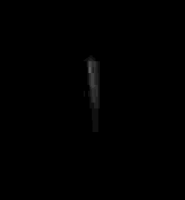
QUOTE (mcaplinger @ Jan 7 2016, 12:11 AM) I'm not thinking this is going to be much of an issue for most applications. Here a 16x enhanced crop of EFB01, probably showing the sharp ghost of our Moon:
Since it's TDI 1, I've been interpreting the elongated shape as reflected light rather than smear (with some uncertainty). It seems, the light of the moon happened to hit only one (causing the sharp ghosts) of at least three areas causing ghosts. I'm expecting this to cause issues mainly in cases, when a bright target is displaced about 18 degrees (vertically) relative to a dark target of interest, think e.g. at attempts to observe auroras, or at areas which are dark in one spectral band. QUOTE ... there may be some imaging during approach and earlier on the first orbit ... Some images similar to the Moon image during approach addressing specifically the possibly reflecting or smearing areas would certainly help calibration. QUOTE (mcaplinger @ Jan 7 2016, 12:11 AM) I'm still more concerned about band-to-band registration, for which no perfect model yet exists. Pinning this down to subpixel precision looked much easier to me than quantifying the fuzzy stray light and smear, so I was inclined to do the difficult things first. But just to be sure, I'll be going to shift priorities towards image geometry, since this needs to be elaborated anyway, including the geometry of the ghosts. |
|
|
|
|
|
|

|
Lo-Fi Version | Time is now: 16th April 2024 - 09:10 PM |
|
RULES AND GUIDELINES Please read the Forum Rules and Guidelines before posting. IMAGE COPYRIGHT |
OPINIONS AND MODERATION Opinions expressed on UnmannedSpaceflight.com are those of the individual posters and do not necessarily reflect the opinions of UnmannedSpaceflight.com or The Planetary Society. The all-volunteer UnmannedSpaceflight.com moderation team is wholly independent of The Planetary Society. The Planetary Society has no influence over decisions made by the UnmannedSpaceflight.com moderators. |
SUPPORT THE FORUM Unmannedspaceflight.com is funded by the Planetary Society. Please consider supporting our work and many other projects by donating to the Society or becoming a member. |
|