1/4 Scale Rover Project |

  |
1/4 Scale Rover Project |
 Jan 9 2006, 02:45 AM Jan 9 2006, 02:45 AM
Post
#1
|
|
|
Senior Member  Group: Members Posts: 2998 Joined: 30-October 04 Member No.: 105 |
Going beyond the desktop model of a Rover, I'm building a scale model Rover at 1:4 scale. There is an abundance of photographs of the Rovers and the US Patent Office website has accurate line drawings in the patent files of the Rover. Go to the USPO website and search for D487,715 and D488,093 .
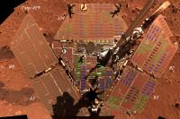
The first step is to build the Warm Equipment Box (WEB), which is the core of the Rover. At 1:4 scale, the WEB is 8.5" long, 5.5" wide and 4" high. The attached images are the initial, rough build of the WEB and the Rover Equipment Deck (RED). I'm playing with the idea of making this a functional, radio-controlled scale model of the Rover, but this may be too much of a leap making it pretty _and_ functional. What I may do is make the display scale model first, then a non-scale workable model for R&D and then a working scale model. I'm working on making realistic-looking solar cells. The actual dimension is 4cm x 2cm, which is 10mmx5mm at this scale, and there are 1100 of 'em. My first guess for material to surface the solar cells with is 1/4" magnetic tape (like videotape); it has a reasonable color and bright luster. Ideas and suggestions are welcome. --Bill -------------------- |
 |
 
|
|
Jan 9 2006, 03:44 PM
Post
#2
|
|
|
Senior Member Group: Members Posts: 1636 Joined: 9-May 05 From: Lima, Peru Member No.: 385 |
The cover to imitate the solar panels, I think the best idea is to go a bookstore and ask him and he might have a better idea of that! My idea is to put in many strips of roll picture camera and it might look alike to solar panels.
Rodolfo |
|
|
|
|
Jan 9 2006, 04:05 PM
Post
#3
|
|
 Member Group: Members Posts: 510 Joined: 17-March 05 From: Southeast Michigan Member No.: 209 |
QUOTE (Bill Harris @ Jan 8 2006, 09:45 PM) I'm playing with the idea of making this a functional, radio-controlled scale model of the Rover  Ooooo - how about going even further and adding some automatic control? You could conceivably do it with the LEGO Mindstorms RCX brick. It's relatively inexpensive and easy to program, though with one RCX brick you are limited to three inputs and three outputs. ISTR people making multiple RCXs talk with each other over an IR link, which would get you more I/O. And you'd probably need to build some interface electronics to make the outputs control bigger motors. And there's also a vision kit that accepts input from a webcam, so that will cover your FHAZ/RHAZ system  I'd love to work on a project like this, but I'm afraid my wife would come out to the garage, cross her arms, tap her foot, and remind me of all of my current "Honey-Do" items that aren't getting attention. Please accept my vicarious participation 
-------------------- --O'Dave
|
|
|
|
|
Jan 9 2006, 05:11 PM
Post
#4
|
|
|
Senior Member Group: Moderator Posts: 4279 Joined: 19-April 05 From: .br at .es Member No.: 253 |
QUOTE (Bill Harris @ Jan 9 2006, 03:45 AM) I'm working on making realistic-looking solar cells. The actual dimension is 4cm x 2cm, which is 10mmx5mm at this scale, and there are 1100 of 'em. My first guess for material to surface the solar cells with is 1/4" magnetic tape (like videotape); it has a reasonable color and bright luster. Ideas and suggestions are welcome. Maybe printing the re-scaled solar cells on glossy paper, or also normal printing paper but covered with a plastic protection? |
|
|
|
|
Jan 9 2006, 05:15 PM
Post
#5
|
|
|
Founder Group: Chairman Posts: 14432 Joined: 8-February 04 Member No.: 1 |
they need to have quite a bit of depth to them though - they're a few mm thick - and they have two 'levels' to them, with the little red corner on them etc etc
My suggestion would be very dark blue or black acrylic sheets, cut to appropriate shapes, and then two stuck together to allow that little corner to stick out If I ever got round to something like this - I'd spend months adding all the little wires to and from the solar arrays Doug |
|
|
|
| Guest_PhilCo126_* |
Jan 9 2006, 06:09 PM
Post
#6
|
|
Guests |
Won't be easy to make the arm and Athena science suite instruments ... Looking forward how You're going to do those parts.
Good luck !
|
|
|
|
|
Jan 9 2006, 07:28 PM
Post
#7
|
|
 Dublin Correspondent Group: Admin Posts: 1799 Joined: 28-March 05 From: Celbridge, Ireland Member No.: 220 |
QUOTE (Bill Harris @ Jan 9 2006, 03:45 AM) I'm working on making realistic-looking solar cells. The actual dimension is 4cm x 2cm, which is 10mmx5mm at this scale, and there are 1100 of 'em. Do you know this for certain? Thing is I've counted em and I get ~507 cells and I figure the most likely dimension is 8cmx3cm yielding an actual cell surface area of 1.21 m^2. I'd love to know what the exact dimensions actually are. |
|
|
|
|
Jan 9 2006, 08:01 PM
Post
#8
|
|
|
Senior Member Group: Members Posts: 2998 Joined: 30-October 04 Member No.: 105 |
The solar panels are going to be an interesting challenge. At 1/4 scale each panel "wing" is going to be about 15"x5" and the individual solar cells will be 0.4"x0.2" (10mm x 5mm), so it is large enough to be workable.
If you'll look at the panels, the solar cells are arranged in groups of cells, say 10-by-2 cells attached to the top odf the panels. Breaking it down into groups like this makes it quite manageable-- I've taken a USPO line drawing and have marked off the panels into groups. I'll make pieces the size and shape of each group out of 1/64" plywood and glue the individual solar cells made of 1/64" ply to the groups and then glue the groups to the panel wings, thereby giving a 3-D quality to the assembly. And, yes, individual wires from each cell is an option. Fine copper wire can be salvaged from small transformers, and glued and painted. I want the solar panels to look detailed from 6" away. The nightmare will be all the bundles of wires around the WEB; there is minimal photo documentation of them. But I'll tackle each new detail as it comes up; this is what makes modeling a challenge. I'm more and more inclined to concentrate on a detailed display model initially, and develop a non-scale but functional rover as a parallel project. There are a lot of constraints added by the scale provision; once I get scale figured out and functional debugged, it will be easier to combine the two. --Bill -------------------- |
|
|
|
|
Jan 9 2006, 09:34 PM
Post
#9
|
|
|
Founder Group: Chairman Posts: 14432 Joined: 8-February 04 Member No.: 1 |
QUOTE (Bill Harris @ Jan 9 2006, 08:01 PM) The nightmare will be all the bundles of wires around the WEB; there is minimal photo documentation of them. No harm in giving Steve and/or Jim a quick email, they're bound to have the odd photo that might be handy. Doug |
|
|
|
|
Jan 9 2006, 10:57 PM
Post
#10
|
|
|
Dublin Correspondent Group: Admin Posts: 1799 Joined: 28-March 05 From: Celbridge, Ireland Member No.: 220 |
QUOTE (helvick @ Jan 9 2006, 08:28 PM) Do you know this for certain? Thing is I've counted em and I get ~507 cells and I figure the most likely dimension is 8cmx3cm yielding an actual cell surface area of 1.21 m^2. I'd love to know what the exact dimensions actually are. Just following up. I counted them again very carefully and now get 499. And by taking the published dimensions of the rover (1.6m x 1.2m for the deck) and doing al take off of about a dozen cells scattered around the deck I get an average width of 6.5cm and height of 4.0cm with an error of +-5%. There was a lot of tweaking of the cell strings - only about 250 or so are actually placed in continuous strings of 10-13. Damn fine tiling job that. :-) I would love one of those wotsits, err the-document-who-shalt-not-be-named. Oh well. |
|
|
|
|
Jan 9 2006, 11:04 PM
Post
#11
|
|
 Senior Member Group: Members Posts: 2488 Joined: 17-April 05 From: Glasgow, Scotland, UK Member No.: 239 |
The Yahoo! Space Modeler's Forum is probably worth a look, I've not visited it for a while but there were certainly some similar projects (including a Lunokhod 2) being discussed there.
http://groups.yahoo.com/group/space-modelers/ http://groups.yahoo.com/group/space-modele...s/Lunokhod%202/ Bob Shaw -------------------- Remember: Time Flies like the wind - but Fruit Flies like bananas!
|
|
|
|
|
Jan 10 2006, 01:43 AM
Post
#12
|
|
|
Senior Member Group: Members Posts: 2998 Joined: 30-October 04 Member No.: 105 |
Helvick, our messages crossed in the aether:
I got the solar cell/panel dims from "MER Technical Data" at http://hobbiton.thisside.net/rovermanual/ QUOTE 3.1 Solar arrays: The MER solar arrays are composed of 55 parallel strings of 20 cells each of 2cm x 4cm GaAs/Ge cells. Each string within the array is diode isolated. The total solar array area on the MER is 1.2 square meters. 55x20 is 1100. I drew the "solar cell groups" and the 4x2 cm seems to match those footprints reasonably well. But I'll double check those cell dimensions from the USPO line drawings. Modeler's Forum? Hmmm, I'll check that out. --Bill -------------------- |
|
|
|
|
Jan 10 2006, 10:23 AM
Post
#13
|
||
|
Dublin Correspondent Group: Admin Posts: 1799 Joined: 28-March 05 From: Celbridge, Ireland Member No.: 220 |
QUOTE (Bill Harris @ Jan 10 2006, 02:43 AM) http://hobbiton.thisside.net/rovermanual/ 55x20 is 1100. I drew the "solar cell groups" and the 4x2 cm seems to match those footprints reasonably well. But I'll double check those cell dimensions from the USPO line drawings. That number is from the "Power Aware Computing and Communication" document and dates from 2000. The description was probably valid at the time but the details were significantly reworked before the rovers flew. 1100 Cells at 4x2cm would give 0.88m^2 of cell surface area which is definitely too low, such a panel would have had a peak power output of around 600-650 Watt hours per day. There are definitely only ~500 cells though see the attached crudely tagged Spirit deskpan.
The USPO Line drawings that I have are undimensioned which is a bit of a pain. Adding some approximate dimensions to them given that we know some precise values (like the Pancam\Navcam separation distances should be doable. |
|
|
|
|
|
|
Jan 10 2006, 11:08 AM
Post
#14
|
|
|
Senior Member Group: Members Posts: 2998 Joined: 30-October 04 Member No.: 105 |
Whew, that took some work. I'm using a similar deck pan, and I'll add yours into the equation. I don't think it matters what the _exact_ individual cell size and count is, I'll delineate the several cell groups, and see what the cell size is from that measurement.
Based on that MER tech pamphlet and other sources, my dimensional reference is that the WEB is 34" long, 21.6" wide, 14.4" deep and the RED is based on an equilateral triangle 48.8" on a side. Other measurements confirm that these dims are close to correct. If not, it's what I am using, and I'll proportion everything else to fit (it may end up being 3.957:1 instead of 4:1). Knowing a couple of key dimensions on the line drawings I can carefully measure components using a dial caliper (measures to .001", which is "empty accuracy") and using the reference dims I can proportion everything else. Thanks for the feedback. --Bill -------------------- |
|
|
|
|
Jan 10 2006, 11:53 AM
Post
#15
|
|
 Senior Member Group: Members Posts: 3419 Joined: 9-February 04 From: Minneapolis, MN, USA Member No.: 15 |
Reminds me of when I was 14 years old, and bored to death one winter day -- I took my 1/48th-scale Apollo Lunar Module model and started taking measurements here and there... and before I knew it, I had constructed, out of cardboard, a 1/6th-scale Descent Stage main body. Using a school ruler and my knowledge of scaling equations, I did all the math in my head and measured out the entire LM.
I was rather proud of that scratch-built model, though it went the way of all things many, many years ago. Its landing gear could be stowed and the supports all worked properly, it had a deployable MESA table, complete with a tiny B&W TV camera model stowed in the MESA, and the SEQ bay doors opened up, too. There was even a tiny canister attached to the ladder on the front leg that contained a 1/6th-scale American flag, complete with two-piece flagpole and a stiffening rod to hold the flag out. It was all made out of cardboard and tin foil, of course -- esxcept I *did* use some old, frayed tinkertoys to reinforce the landing legs. Just think of it as doweling placed inside form-wrapped cardboard tubes. I must say, I had a great time building it. I'm sure you'll have a great time building your MER model, too! -the other Doug -------------------- The trouble ain't that there is too many fools, but that the lightning ain't distributed right. -Mark Twain
|
|
|
|
|

|
Lo-Fi Version | Time is now: 25th April 2024 - 01:31 AM |
|
RULES AND GUIDELINES Please read the Forum Rules and Guidelines before posting. IMAGE COPYRIGHT |
OPINIONS AND MODERATION Opinions expressed on UnmannedSpaceflight.com are those of the individual posters and do not necessarily reflect the opinions of UnmannedSpaceflight.com or The Planetary Society. The all-volunteer UnmannedSpaceflight.com moderation team is wholly independent of The Planetary Society. The Planetary Society has no influence over decisions made by the UnmannedSpaceflight.com moderators. |
SUPPORT THE FORUM Unmannedspaceflight.com is funded by the Planetary Society. Please consider supporting our work and many other projects by donating to the Society or becoming a member. |
|