Printable Version of Topic
Click here to view this topic in its original format
Unmanned Spaceflight.com _ Juno _ Beginner level projection
Posted by: adamg Nov 6 2019, 11:50 PM
Hi,
I'm trying to do the mapping just using SPICE for the Junocam images rather than going through ISIS. It might seem like I'm making life difficult for myself but I just wanted to make sure I'm doing the bare minimum amount of processing so it looks as close to a non-spinny-push-frame image as I can. I'm making all the beginner mistakes but I can't seem to figure out what they are so I was hoping someone might give me a hint?
First I want to figure out how far Jupiter is because I want to have anything that didn't hit Jupiter get mapped to a sphere that hits Jupiter. This means any lens effects can get mapped in space near where they originated from which should hopefully make the edges of the planet seem less processed:
[jupiterPos, jupiterLt] = spice.spkpos('JUPITER', et0, 'JUNO_SPACECRAFT', 'NONE', 'JUNO')
jupiterDistance = np.linalg.norm(jupiterPos)
Then I go through all the undistorted Junocam pixel vectors and figure Jupiter intercept points in the IAU_JUPITER frame so now I have a point cloud of all the planet mapped pixels:
[point, trgepc, srfvec, found ] = spice.sincpt(
'Ellipsoid', 'JUPITER', et,
'IAU_JUPITER', 'LT+S', 'JUNO_SPACECRAFT',
'JUNO_JUNOCAM', v)
If it didn't find an intersection then I figure out where that invisible sphere is going to be by extending out the pixel vector by the separation and move that to the IAU_JUPITER frame:
direction = np.array(v)
pos = direction*jupiterDistance/np.linalg.norm(direction)
rotationMatrix = spice.pxform('JUNO_JUNOCAM','IAU_JUPITER',et-jupiterLt)
pos = spice.mxv(rotationMatrix, pos)
It works terribly! I seem to have a timing error in the frame offsets that seems suspiciously close to the light time between Jupiter and Juno and the sphere that catches all the sincpt misses is completely miles off. I've been staring at the code for a while and not figuring my mistake, I was hoping someone might point out where I've gone wrong.
Many thanks
Adam
Posted by: Gerald Nov 7 2019, 03:21 AM
Hi Adam,
I'm not even using the SPICE library. But for anyone being used to the SPICE environment, or for other ways of cross-checking, it would probably be helpful, if you could provide a set of SPICE kernel files you are applying, together with the name of the raw JunoCam image file. This would help to decide, whether your observed deviation from the expected result is caused by the data or by your code (or both). I'd also suggest to read the JunoCam instrument kernel file.
Posted by: Bjorn Jonsson Nov 7 2019, 06:41 PM
In addition to what Gerald mentioned, I'd start by using only the instrument (in this case JunoCam) boresight vector and make sure it intersects Jupiter at the correct location. Once this works correctly you know that any errors are elsewhere (e.g. in how you map individual pixels to rays in 3D space).
Also if you haven't done so it might also be a good idea to first make sure your code works correctly for a camera that is less complicated to handle than JunoCam. A framing camera (e.g. Cassini) is easier.
Posted by: mcaplinger Nov 7 2019, 10:53 PM

I'm not sure what you're trying to do (not following the "invisible sphere" stuff) and I have the suspicion that you're counting the light time twice, but all that said there are known timing errors of roughly six pixels 1 sigma in the Junocam start time that you need to correct for. We're working on pushing updates to the PDS but it'll probably be a while before that happens. In the meantime, which images are you working with?
Also, make sure you are using the reconstructed SPK files.
Posted by: adamg Nov 7 2019, 11:16 PM
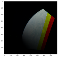
Thanks for the replys. I actually did start off using the boresight vector and it certainly looked like I was on the right track. Then I moved to looking for the edge of the planet from the undistort method in the IK and including the bias delay it looked pretty good other than being off by an additional delay (yes, I've definitely been through the IK file). I was assuming it was clock drift but later noticed it was similarish to the light time so I'm wondering if I'm not correcting for light times properly. I added the found image to this post where red means it didn't find Jupiter in that pixel's direction.
My kernal uses the following files:
\begindata
KERNELS_TO_LOAD = ( 'naif0012.tls','JNO_SCLKSCET.00092.tsc','de438s.bsp',
'jup310.bsp','juno_rec_orbit.bsp','juno_struct_v04.bsp','juno_v12.tf',
'juno_junocam_v03.ti','pck00010.tpc','juno_sc_nom_110807_171016_v01.bc' )
\begintext
And I'm using image JNCR_2017244_08C00109_V01.IMG
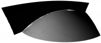
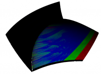
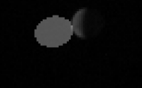
I attached the point cloud the first few framelets make and it looks reasonably hopeful. It got really ulgy really fast when I tried making that imaginary sphere to map the planet misses onto. You can see the planet on the right and the sphere way off on the left not attached so I've obviously messed up my SPICE calls. I've had a pretty hard look and I think it's my failure to grasp something rather than a simple coding error. My guess is I actually have two separate problems, one in my attempt to make an imaginary sphere just by multiplying a direction vector and the other in my light time correction flag for the sincpt call. That's why I just added those calls in the post.
Thanks again.
Adam

|
|
|
Posted by: mcaplinger Nov 7 2019, 11:24 PM
Don't use the nom C kernels, use the rec C kernels.
Our measurements show that the timing for that image was off by 3 pixels or 3*3.2 milliseconds.
Not important, but still not following the invisible sphere stuff.
Posted by: adamg Nov 7 2019, 11:27 PM
Also, make sure you are using the reconstructed SPK files.
Just to explain that sphere thing, my plan is to map every pixel to a point in space and then turn it back to an image from nearst points to vectors coming from the spacecraft's location. So the points not mapped to a planet need to get mapped somewhere nearish so I thought a sphere centered on Juno and intersecting with the middle of Jupiter would be some kind of start.
Posted by: adamg Nov 7 2019, 11:30 PM
Our measurements show that the timing for that image was off by 3 pixels or 3*3.2 milliseconds.
Not important, but still not following the invisible sphere stuff.
Thanks for the timing error, that means it's definitely misuse of SPICE, my error is similar to the light time (230 odd ms).
Posted by: mcaplinger Nov 7 2019, 11:51 PM
Keep in mind that SPICE is computing the distance to the center of Jupiter, not to the visible surface, so if you're using the former when you mean the latter, there's an error there, which if you're close to the planet is a pretty big error.
Try not doing any light time correction at all. See the cautionary note in the comments for the sincpt function, etc.
Posted by: Brian Swift Nov 8 2019, 07:17 AM
Hi Adam, Welcome to/from the JunoCam raw processing community.
Mapping pixels that dont intercept Jupiter to an invisible sphere is a cool idea, its what my processing pipeline does. ;-) I refer to this sphere as the backstop surface. As far as I know, none of the other JunoCam pipelines use this technique.
My pipeline is implemented as a Mathematica notebook available as Juno3D at https://github.com/BrianSwift/JunoCam/tree/master/Juno3D
While my software is permissively free, unfortunately Mathematicas licensing costs create a significant barrier to its usability.
On your sincpt, double check that 'JUNO_SPACECRAFT',
'JUNO_JUNOCAM' are in the correct parameter position. My calling sequence is
but my bridge from Mathematica to the SPICE library may have a different calling sequence than pythons. (Note, don't try substituting "JUNO", for "JUNO_JUNOCAM". I don't use JUNO_JUNOCAM because my pipeline uses a different camera model than found in SPICE.)
With respect to projecting non-intercepting imagery onto a backstop sphere,
rather than moving a point intersecting the backstop sphere into the IAU_JUPITER frame
I define my backstop sphere in the IAU_JUPITER frame and then just compute where the pixel vector intercepts the backstop.
Also, my backstop sphere radius is set to intersect just inside the limb rather than at Jupiter's core to avoid a camera distance discontinuity between intercepting and non-intercepting imagery.
Also note Jupiters visible limb can be at a higher altitude (by tens of km) than the SPICE 1-bar limb. This is noticeable with imagery collected near perijove.
Finally, youll find a lot of processing discussion under the Juno PDS data topic at http://www.unmannedspaceflight.com/index.php?showtopic=8143
Posted by: mcaplinger Nov 8 2019, 03:27 PM
Most cartographic pipelines map lat/lon on the target into pixel coordinates on the detector, and the mapping in the other direction is typically only used to determine the lat/lon range of the output map. Of course when doing the lat/lon->x,y mapping you have to account for points that are hidden from the camera by the planet itself.
As for the height of the actual limb relative to the 1-bar spheroid -- this is possibly a factor, but the limb is pretty far away even near perijove so it doesn't make a huge difference. For our timing corrections we ignore this.
Posted by: Gerald Nov 8 2019, 04:39 PM
Be sure, that you don't use a sphere, but a Maclaurin spheroid with the proper polar and equatorial radii, and with the correct axis tilt. You should then ideally end up with an error of less than 100 km induced by deviations due to Jupiter's internal mass distribution and dynamics, and due to the uncertainty of the pressure level of Jupiter's cloud tops. Using a sphere of some mean radius would cause errors on the order of 2000 km.
Posted by: Brian Swift Nov 8 2019, 05:56 PM
The sphere being discussed here is not a model for Jupiter's shape, it is a synthetic surface onto which imagery that does not intercept Jupiter can be projected.
Posted by: adamg Nov 9 2019, 12:15 AM
We're totally on the same page Brian.
The help funtion returns sincpt(method, target, et, fixref, abcorr, obsrvr, dref, dvec) which matches the C spice documentation so the penultimate item is the frame for the direction vector which is JUNO_JUNOCAM. While I wait for the Mathematica viewer to download I'm going with mcaplinger's suggestion of forgetting about light correction for a first pass and your suggestion of working in the IAU_JUPITER frame. I couldn't tell if you were doing some clever way of intercepting so I just subtracted the scaled pixel vector from the planet-juno separation. I do think my frames weren't right before so I'm refactoring it now to go into the IAU_JUPITER mostly because sincpt says it only works with the body centered frame so that's the least amount of jiggering. I didn't correct for the limb thinking it would only give a smallish error but I see everyone pointing out how far off this will be. In my defence you see all these planet sphere type pictures so I had no idea how close that thing gets!
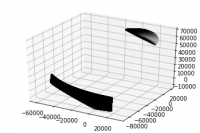
Just to share, the black thing is the sphere that intersects with the middle of Jupiter and has an origin at Juno and you can see how far away the limb is from there. I switched to open3d rather than matplotlib as a viewer and I have to say being able to rotate the point cloud in real time is pretty awesome.
Thanks for everyone being so helpful and that other post is very interesting.
|
Posted by: Brian Swift Nov 10 2019, 07:40 AM
Try not doing any light time correction at all. See the cautionary note in the comments for the sincpt function, etc.
As I read the cautionary note, it only applies in the situation where DREF is same as FIXREF.
From ABCORR description in sincpt doc:
'LT+S' trades some accuracy for speed, which may be relevant if calling sincpt for every pixel.
Posted by: Brian Swift Nov 10 2019, 08:19 AM
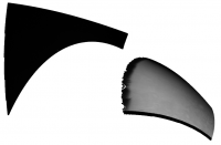
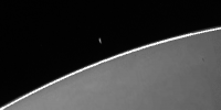
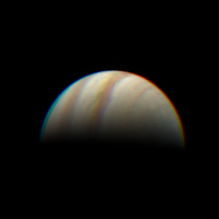
Having a non-cartographic technique that renders rather than discards pixels that don't intercept Jupiter supports creation of images like this showing both moon (Europa?) and Jupiter from PJ8_109.
|
Posted by: Brian Swift Nov 10 2019, 08:41 AM
I'm curious, what is your process to estimate the error? I'm just doing Jupiter limb fits.
Posted by: mcaplinger Nov 10 2019, 03:15 PM
In theory (I've never tried it) it would be possible to remove the camera distortions and stitch the framelets together accounting for spacecraft spin without calling sincpt at all or doing any intercept calculations.
Posted by: adamg Nov 10 2019, 05:15 PM
Absolutely Brian, that's exactly the behaviour I'm looking for, the planet edge looks far more realistic than sphere mapped images. That's why I picked the test image I did, because it had that moon poking out too. Normally I would have just used your script but I think I've become too fascinated with the way SPICE can partition work between groups to not spend a bit more time with it.
Posted by: mcaplinger Nov 10 2019, 07:52 PM
BTW, this isn't the right way to do this. The right way is to use pxfrm2, which takes two different epochs. See the example in the comments for pxfrm2. That may be the source of your error.
I have to confess that my processing chain uses pxform and doesn't correct for the speed of light at all. When it was originally written for low Mars orbiters, this made very little difference. For Juno it makes a little more difference near perijove, and progressively more and more towards apojove.
Posted by: adamg Nov 12 2019, 05:59 PM
Thanks mcaplinger, I've changed it to the following, with the terrible frac in there to line the sphere thing up with the visible edge, I think you can tell what I'm up to from the plot now.
[jupiterPos, jupiterLt] = spice.spkpos('JUPITER', et0, 'IAU_JUPITER', 'NONE', 'JUNO')
pos = frac*direction*jupiterDistance/np.linalg.norm(direction)
rotationMatrix = spice.pxfrm2('JUNO_JUNOCAM','IAU_JUPITER',et, et-jupiterLt*frac)
pos = spice.mxv(rotationMatrix, pos)
pos -= jupiterPos
I've reasoned that the first pos assignment gets where it should be in the camera frame, the rotation does all the light time magic and the subtraction gets the resulting vector translated to Jupiter. It seems to work but it would be comforting if someone could say if this is nonsense that worked by chance. My use of the word "magic" gives an idea of my proficiency in these things.
I switched to the juno_sc_rec_170831_170902_v01.bc kernel like you said and I had to add 10ms to get the edge to line up which agrees with what you said earlier.
Brian, I see your code uses limbpt to find the limb, is that the easiest way do you think?
Many thanks
Adam
|
Posted by: adamg Nov 12 2019, 10:52 PM
I tried the limbpt function (below), not that I really understand the half plane thing, hence stuffing the same z vector in that the example code has. It kind of lines up, I added the points it returns as red and the view is from the underside, I'm assuming that the difference is from the non-roundness of the planet.
limbRet = spice.limbpt('TANGENT/ELLIPSOID','JUPITER',et0,'IAU_JUPITER','LT+S','CENTER','JUNO',[0.0,0.0,0.1],0.01,100,1e-4,1e-6,100)
|
Posted by: mcaplinger Nov 12 2019, 11:09 PM
limbpt is supposed to using the spheroid, so this doesn't seem like a good explanation, but I use edlimb, not limbpt (warning, speed of light not properly handled.)
e = edlimb(radii[0], radii[1], radii[2], vminus(to_targ))
c = pxform("iau_"+targ, "juno_junocam", t)
org = vadd(e.center, to_targ)
for th in range(-1800, 1800):
p = vadd(org, vadd(vscl(math.cos(math.radians(th/10.0)), e.semi_major), vscl(
math.sin(math.radians(th/10.0)), e.semi_minor)))
x, y = junocamlib.vector2xy(mxv(c, p), band)
Posted by: Brian Swift Nov 12 2019, 11:44 PM
I don't recall being aware of edlimb when I developed the code that uses limbpt.
edlimb looks like a simpler interface, and is probably much faster than limbpt.
However, I notice the edlimb example uses a light time correction relative to
Jupiter's center. In limbpt, specifying the aberration correction
locus corloc="ELLIPSOID LIMB" applies light time correction to each limb point.
Since the distance to the limb can be as low as 22000km, there could be a difference
in light times of 151ms which is equivalent to about 47 pixels.
When everything is working correctly, (and you have a good estimate for the image start time)
you should be able to identify spice limb pixels on both the moon and jupiter.
(Staying aware that spice limb pixels on jupiter may be slightly within the junocam visible limb).
When the "Limb Marking" code in the Juno3D pipeline is enabled, it marks pixels along
the limb in the raw data prior to processing, which can be handy for debugging and
start time jitter analysis.
Posted by: adamg Nov 14 2019, 11:34 PM
Update: I think my issue is that the transform doesn't do light stuff which I was assuming. So the first has apparent position and the second doesn't. I've tried shifting everything by the difference between the corrected and uncorrected limb to get it equivalent to the apparent poisition but not luck yet :-/
---
I've been looking at this pretty carefully and I'm not seeing my error, when I map this back to the juno location it comes out evenly spaced (so I'm mapping back to the same spot) but there's a gap. So the result from one branch is being mapped a little bit off the other. If someone could give me a hint that would be great. I used the LT method thinking it would match method wise but I tried a few and it makes very little difference.
Thanks for any help.
frac = 0.63
jupiterDistance = np.linalg.norm(jupiterPos)
# This fragment has the pixel direction vectors already calculated as "direction"
with spice.no_found_check():
[point, trgepc, srfvec, found ] = spice.sincpt(
'Ellipsoid', 'JUPITER', et,
'IAU_JUPITER', 'LT', 'JUNO',
'JUNO_JUNOCAM', v)
if found:
cloundInd = (thisSlice - sliceLow)*1648*128 + y*1648 + x
pointCloud[cloundInd,:] = point
else:
direction = np.array(v)
pos = frac*direction*jupiterDistance/np.linalg.norm(direction)
rotationMatrix = spice.pxfrm2('JUNO_JUNOCAM','IAU_JUPITER',et, et-jupiterLt*frac)
pos = spice.mxv(rotationMatrix, pos)
pos -= jupiterPos
cloundInd = (thisSlice - sliceLow)*1648*128 + y*1648 + x
pointCloud[cloundInd,:] = pos
|
Posted by: adamg Nov 22 2019, 12:57 AM
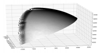
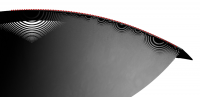
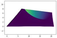
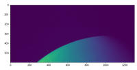
Took a while. It wasn't light travel time because the error introduced is too small. It was that I tried hand fitting the limb which gave a timing error which gave an angle offset from the spacecraft spin. So doing a limb search got the timing to line up. I scaled everything by its dot product to the Jupiter vector so it ended up on a plane. I dropped the extra dimension by taking the first row as one basis vector and then taking a column as another vector, made it orthonormal then projected everyting onto those vectors. It gave the first picture and I did a KD nearest neigbour search to rasterize it, second image. I kind of like the projection to a plane as I feel it makes it more like a real single camera, at least it'll behave just like a pinhole camera.
The projection to an imaginary Juno centered sphere is nice because it doesn't need any spice ray projections so takes no time and as I'm unprojecting it from the same point of view the Jupiter mapping bit isn't actually doing anything (other than some super serious finding of errors!). I feel the sphere project -> plane -> dimension reduction can easily be made into a single stage so you wouldn't actually have to do the imaginary sphere thing (Though honesty it's not that bad as it is). That should get it way faster than what I have so then a super simple pipeline can use all the hard work that went into the SPICE kernels to make nicely stitched pictures. I'm sure the nearest neighbour search can be improved on too because the data has structure so you always know which direction will get you closer, anyone know of an implementation of such a thing?
|
|
Posted by: scalbers Nov 22 2019, 08:07 PM
Good to see - I would guess this also makes it easier to show the atmosphere if one is zoomed in near the limb.
|
|
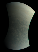
Posted by: adamg Nov 24 2019, 01:34 AM
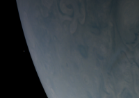
Tried doing color, seems to work. The KD tree was way too slow so I just idiot histogrammed it. I probably need a hit count pass to clean it a bit but it'll do for now. Thanks for the help.
|
|
Posted by: adamg Nov 25 2019, 09:43 PM
Anyone have any good advice on scaling the RGB to give the closest to true color? I tried these two [0.487, 0.408, 0.172] [0.444, 0.341, 0.155] from Brian's flow and I get a strong orange hue. I also tried the coefficients [0.51, 0.63, 1.0] from Gerald's slides and it comes out pretty blue looking. I tried a few and felt like [1,1,0.95] seemed close but I've only seen artistically processed images from Junocam processing that look so different to pictures of Jupiter, I simply don't know any more!
Many Thanks
|
Posted by: Bjorn Jonsson Nov 25 2019, 11:01 PM
I usually multiply by [1, 1.12, 2.3] after decompanding. I'm surprised that [1, 1, 0.95] seemed close - are you decompanding the images before applying these?
Posted by: Brian Swift Nov 26 2019, 10:33 AM
My colorBalance values specify the upper end of the range of the input components, so you'd divide by them.
When rescaled, they are similar to Bjorn's.
1/colorBalance/Min[1/colorBalance] = {1., 1.193, 2.8378}
Posted by: Brian Swift Nov 26 2019, 10:54 AM
I've been wondering, is your natural color process more involved than a scaling?
And also how you derived your color balance values?
My current (too blue) values come from the median of my flat fields. Early on they came from the max values from an image of Europa.
Posted by: adamg Nov 26 2019, 12:26 PM
Sounds like I'm miles off for some reason. I used the RDR product assuming it had already been decompanded, I recall I have a range to 4kish so it has certainly been through something.
Posted by: fredk Nov 26 2019, 02:48 PM
And also how you derived your color balance values?
In particular, shouldn't a colour space matrix transformation to, eg, sRGB be performed from the raw colour channels? That generally can't be approximated by a simple scaling of each channel.
Posted by: adamg Nov 26 2019, 06:14 PM
The RDR data set says "For planetary targets, these values are then scaled such that a white surface at the solar distance at the time of imaging and with the commanded exposure time would have a pixel value of 10,000 data numbers.", so I'm assuming the blue already got scaled before I got to it. I probably ought to use the EDR data set if I want to actually know how it got scaled.
Regarding sRGB, it seems sensible to me that you can scale the linear raw IMG which is what I'm doing but should I be trasforming to sRGB at some point?
Posted by: mcaplinger Nov 26 2019, 09:44 PM
Well, I wrote that, and I don't know how to make it any clearer than that.
"Natural color" requires you to model the human eye response. The Junocam RGB filters are not much like the human eye response (unlike the Bayer pattern used for MSL) so one would have to do something, but I'm not sure what.
In case you care, the EDR-RDR scaling code (after decompanding) is
ref = [111, 4766, 10331, 12669] # ch4, blue, green, red
scale = 16.3
sunrange /= 1.5e8 # km to AU
ex = float(i.info["exposure"])*int(i.info["tdi"])
dnout = int(dn*scale/ex/(ref[f]*(5.2)**2/sunrange**2)*10000)
Posted by: Brian Swift Nov 27 2019, 04:47 AM
My colorBalance scaling is applied to decompanded raw non-calibrated image values. I usually use the "raw" files from the missionjuno.swri.edu, but
have also used PDS EDR files. I haven't worked with the RDR files.
I don't apply a linear to sRGB conversion unless I want to produce a natural-ish contrast image. Not performing the linear to sRGB makes the files from my pipeline display with more contrast.
Posted by: adamg Nov 27 2019, 11:30 AM
Interesting, [1,1.23,2.66] I actually dropped my 0.95 so I think you nailed it.
mcaplinger, sorry I didn't spot your name on the technical report, that was pretty lazy of me! Congratulations on such a successful piece of hardware, as an electronics guy it's the camera itself that's got me interested, I've been very impressed.
Posted by: Brian Swift Nov 27 2019, 06:59 PM
Mike will correct me if I'm wrong, but I believe this is the hardware info for the CCD https://www.onsemi.com/pub/Collateral/KAI-2020-D.PDF
This and various other JunoCam reference links are at the top of the Juno24u notebook on GitHub.
Posted by: adamg Dec 9 2019, 02:25 AM
How are peoples' inter frame delays looking?
In the attached images for JNCE_2016239_01C06109_V01 I added the recommended 1ms inter frame delay (right) and also tried 10ms (left) that got it looking better but not perfect. It's probably not right adding this accumulating delay and seems more likely to be some offset between the three colours instead which is why I ask.
I did see jitter mentioned but I tried a couple of images and the error seems similar between them so it does seem systematic.

|
|
Posted by: mcaplinger Dec 9 2019, 05:50 PM
If we had ever seen anything that would make the interframe delay different than the header value plus 1 msec, we would have said that, but we haven't.
AFAIK nobody has ever said anything about jitter on the interframe delay, only on the start time.
I don't have any measurements for the specific image you posted, but for PJ1-6160 the time offset was about 1 pixel different from the reported values. But again, that's a start time offset, not an interframe delay change.
Posted by: Brian Swift Dec 9 2019, 06:15 PM
I add 0.001035 sec to the INTERFRAME_DELAY value. (This is the value ifdAdjustment in selectedCameraParams in my pipeline.)
The extra 35us beyond the recommended 1ms is probably only relevant to align features that appear in first and last frames of a 360° image.
(BTW, the earth flyby image JNCE_2013282_00C00102_V01.IMG is a good exercise of pipeline robustness)
I did see jitter mentioned but I tried a couple of images and the error seems similar between them so it does seem systematic.
The ~20ms jitter mentioned in juno_junocam_v03.ti just applies to the START_TIME.
Several pipelines perform some type of limb fit to produce a refined start time estimate.
Posted by: Bjorn Jonsson Dec 9 2019, 06:29 PM
The value you add to the interframe delay should always be 1 ms (or close to 1 ms) as Mike said. If you need something like 10 ms there is a bug somewhere in your code. Small deviations from 1 ms are possible due to various factors (limb position uncertainties in especially the hi-res images, possible variations in the haze or cloudtop altitude, tiny variations in Juno's spin rate etc.). I have never gotten values lower than 0.5 ms or higher than 1.5 ms (and I should add that if I get 0.5 or 1.5 that's a big deviation - I usually consider values like these with some suspicion).
I usually determine the start time, end time and interframe delay by measuring the position of Jupiter's limb in the first and last framelets where a significant part of Jupiter's limb is visible. These measurements are then used to automatically determine the actual image time of these two framelets, the interframe delay and from this the start time.
If everything is working correctly the color channel alignment of the resulting image should be close to perfect - maybe a small error (1 pixel or 2 at most) near the image edges in a few cases.
Posted by: adamg Dec 10 2019, 11:20 PM
Thanks guys, apparently I'm a goose. I hard coded the inter frame delay from that P8 image I was looking at before (my code is only a couple hundred lines long so it's a bit bare bones) and this one is different by 8ms.
Posted by: Bill Dudney Aug 3 2020, 02:01 PM
Hello All,
I wasn't sure if I should post here or make a new topic. I'm happy to do that if it fits better with this forum.
I see a discrepancy in what fovtrg_c tells me vs what I get from sincpt_c. I'm sure I'm doing something wrong but I've been hacking around for a week or so (nights and weekends project  and I've not made much progress. So, I figured I'd ask the experts.
My goal here is to understand the data, eventually I want to turn my code into an image processing pipeline. When I powered through and got to a 3d image it looks OK, but is very blurry. The color does not align well etc. So I decided to step back to the beginning and try to ensure everything is doing what I expect. That's when I ran across this image that has Io in it. Using that as a test vehicle has brought into sharp focus the miss that's happening in my code. So I figured it would make a great subject to get my code straightened out before moving back to my 3d image creation.
I've listed my code below with some of the results in the comments. Any pointers to what I'm doing wrong would be most welcome.
Thanks!
I load and parse these files.
JNCE_2019307_23C00028_V01.LBL
JNCE_2019307_23C00028_V01.IMG
furnsh_c("JNO_SCLKSCET.00102.tsc")
furnsh_c("juno_junocam_v03.ti")
furnsh_c("juno_struct_v04.bsp")
furnsh_c("juno_v12.tf")
furnsh_c("naif0012.tls")
furnsh_c("pck00010.tpc")
furnsh_c("trimmed_jup310.bsp")
furnsh_c("juno_sc_rec_191102_191104_v01.bc")
furnsh_c("spk_rec_191010_191201_191210.bsp")
// startTime (from LBL) - 2019-11-03T22:26:16.510
// frame 29
// from the juno_junocam_v03.ti kernel
// INS-61500_START_TIME_BIAS = 0.06188
// INS-61500_INTERFRAME_DELTA = 0.001
// from the LBL file
// INTERFRAME_DELAY = 0.371 <s>
// 2019-11-03T22:26:16.510 + INS-61500_START_TIME_BIAS + (0.371 + 0.001) * frameNumber
// so frame time is:
// 2019-11-03T22:26:27.35988
str2et_c("2019 Nov 03 22:26:27.360", &frameTime)
str2et_c returned 6.26092e+08
fovtrg_c("JUNO_JUNOCAM_RED", "IO", "ELLIPSOID", "IAU_IO", "LT+S", "JUNO", 6.26092e+08)
fovtrg_c returned true
// Examaning the image from the red part of frame 29 I see Io is present on
// pixel 154, 124
// and several others, but that one is kind of in the 'center' of the visible Io
// I'm happy to upload the image I'm referring to. My code takes the IMG data from the PSD file (mentioned above) and turns that into a PNG file.
// I tried two approaches to finding the pointing vector,
// bilinear interpolate over the pointing vectors in the kernel
// INS-61503_FOV_BOUNDARY_CORNERS = (
// -0.47949606, 0.09218676, 0.87268845
// -0.47518685, 0.16768048, 0.86375964
// 0.48724863, 0.16654879, 0.85723408
// 0.49166330, 0.09156385, 0.86595800
// )
// u 0.081468 ((154 - 23) / 1608)
// v 0.96875 (124 / 128)
bilinearInterpolate(0.081468, 0.96875, [
{-0.479496, 0.0921868, 0.872688}
{-0.475187, 0.16768, 0.86376}
{0.487249, 0.166549, 0.857234}
{0.491663, 0.0915639, 0.865958}
]
pointing = {-0.396892, 0.16523, 0.863507}
sincpt_c("Ellipsoid", "IO", 6.26092e+08, "IAU_IO", "CN+S", "JUNO", "JUNO_JUNOCAM", {-0.39689193, 0.1652304, 0.86350652})
sincpt_c returned false
// I also implemented the distord/undistort camera model
// pixel = {154, 124}
// pointing = {-0.398252, 0.166199, 0.902094}
sincpt_c("Ellipsoid", "IO", 6.26092e+08, "IAU_IO", "CN+S", "JUNO", "JUNO_JUNOCAM", {-0.39825207, 0.16619926, 0.90209373})
sincpt_c returned false
// I also spent some time adding an arbitrary time offset (up to 0.1 seconds, by a 0.025 increment)
// and I do end up with intersections but they are several pixels to the left of the captured image.
Posted by: mcaplinger Aug 3 2020, 03:24 PM
// bilinear interpolate over the pointing vectors in the kernel
This is certainly not the right thing to be doing. I know you tried it both ways and the second way is the correct approach.
Post the code by which you actually go from pixel x,y to Junocam frame pointing vector unless it's identical to the code given in the kernel. You want to be going in the correct direction (distorted to undistorted).
It would also be diagnostic if you computed the Io-to-Juno vector and looked at the angle between the pointing vector and that vector (in the same frame) to see how close they are. It's easy for sincpt to miss with the smallest of errors, and Io is obviously very small.
Posted by: Bill Dudney Aug 3 2020, 06:42 PM
Post the code by which you actually go from pixel x,y to Junocam frame pointing vector unless it's identical to the code given in the kernel. You want to be going in the correct direction (distorted to undistorted).
It would also be diagnostic if you computed the Io-to-Juno vector and looked at the angle between the pointing vector and that vector (in the same frame) to see how close they are. It's easy for sincpt to miss with the smallest of errors, and Io is obviously very small.
Thanks Mike,
Sorry to ask you to translate from Swift.
Here is my code:
// INS-61503_DISTORTION_K1 = -5.9624209455667325e-08
// INS-61503_DISTORTION_K2 = 2.7381910042256151e-14
// INS-61503_DISTORTION_X = 814.21
// INS-61503_DISTORTION_Y = -151.52
public func pointingVectorFor(pixelCoord: SIMD2<Double>) -> SIMD3<Double> {
/*
and the following takes an XY coordinate in Junocam framelet
coordinates and produces a vector in the JUNO_JUNOCAM reference
frame (of arbitrary length).
cam[0] = x-cx
cam[1] = y-cy
cam = undistort(cam)
v = [cam[0], cam[1], fl]
*/
let undistorted = undistort(pixelCoord: pixelCoord - distortionModel.offset)
return SIMD3<Double>(x: undistorted.x, y: undistorted.y, z: distortionModel.fl)
}
/*
def distort(c):
xd, yd = c[0], c[1]
r2 = (xd**2+yd**2)
dr = 1+k1*r2+k2*r2*r2
xd *= dr
yd *= dr
return [xd, yd]
*/
let r2 = length_squared(pixelCoord - distortionModel.offset)
let dr = 1.0 + distortionModel.k1 * r2 + distortionModel.k2 * r2 * r2
return pixelCoord * dr
}
func undistort(pixelCoord: SIMD2<Double>) -> SIMD2<Double> {
/*
def undistort(c):
xd, yd = c[0], c[1]
for i in range(5): # fixed number of iterations for simplicity
r2 = (xd**2+yd**2)
dr = 1+k1*r2+k2*r2*r2
xd = c[0]/dr
yd = c[1]/dr
return [xd, yd]
*/
var current: SIMD2<Double> = pixelCoord
for _ in 0..<5 {
let r2 = length_squared(current - distortionModel.offset)
let dr = 1.0 + distortionModel.k1 * r2 + distortionModel.k2 * r2 * r2
current = pixelCoord / dr
}
return current
}
On the pointing vs position...
//spkezr_c returned state vector = {383394, -72976.8, 2221.98, -21.9864, -1.4944, -53.9273}, light time 1.30185
// position normalized:
// (0.98234650459544559, -0.18698377487311099, 0.0056932278465209587)
// -0.39825207416281955, 0.1661992570141925, 0.90209372705553315
dot(positionNormalized, pointing)
// -0.41716227233230763
// not correct...
Thanks again!
Posted by: mcaplinger Aug 3 2020, 08:26 PM
...// not correct...[/code]
You didn't transform the Io vector into the Junocam frame.
I suggest we take this offline since I doubt it's of much interest to the forum. You should have my email because we went over a lot of this back in 2016. Though actually, maybe someone else will have more insight into what's going on with your code.
Posted by: Bjorn Jonsson Aug 3 2020, 09:31 PM
I haven't looked at the code in any detail so I don't know if this is of relevance here but my single biggest lesson with SPICE is probably: Understand the SPICE reference frames and use them a lot (of course there are many more things you need to know). Knowing how to use them results in shorter, simpler code among other things (and almost certainly fewer bugs).
That said, I often find discussion like the posts above interesting.
Posted by: Bill Dudney Aug 3 2020, 10:02 PM
That said, I often find discussion like the posts above interesting.
Thanks Bjorn,
I'm glad I could provide an interesting conversation
The crazy thing about this whole endeavor has been how much there is to learn. I have some experience in 3D programming and lots of general programming exp. My degrees is in aero-engineering so I'm no stranger to this kind of stuff, but I'm still clueless despite many many hrs reading, studying any playing around with Spice.I love it, it's so much fun to build things like this!
And thanks for all you've done with the Juno data. It is one of the many inspirations of me wanting to keep going.
TTFN,
-bd
Posted by: Bill Dudney Aug 3 2020, 10:09 PM
I suggest we take this offline since I doubt it's of much interest to the forum. You should have my email because we went over a lot of this back in 2016. Though actually, maybe someone else will have more insight into what's going on with your code.
Thanks for the response!
I have read and re-read the email exchange from 2016. Thank you so much for taking the time to help me out again! This project has been on a shelf for quite a while and I'm just starting to get back to the point that I understand most of what I'm trying to do.
I did that pointing vs position code in a hurry over lunch so clear 'in a hurry' mistake.
I take from the conversation thus far that I'm on the right track I'm just making boneheaded mistakes like this one. If that's true I will keep checking and double checking my code. If the original code path is off in the weeds I'd love to hear about that as well.
I'll do the transform and repost the results when I get a chance to get back to it this evening.
I'm happy to take this off line, but in case there are others out there trying to do stuff with this data it might be meaningful to see it written up where google can find it.
Thanks again,
-bd
Posted by: Bill Dudney Aug 4 2020, 02:29 PM
I suggest we take this offline since I doubt it's of much interest to the forum. You should have my email because we went over a lot of this back in 2016. Though actually, maybe someone else will have more insight into what's going on with your code.
I have a misunderstanding or some assumption that is off somewhere. I really appreciate you taking the time to help me find and correct it.
I expect these two calls to be equal and opposite:
spkezr_c returned state vector = {383394, -72976.8, 2221.98, -21.9864, -1.4944, -53.9273}, time = 1.30185
length(383394, -72976.8, 2221.98, -21.9864,) 390231.12745828484
spkezr_c("IO", 6.26092e+08, "IAU_IO", "LT+S", "JUNO")
spkezr_c returned state vector = {-383346, 72946.4, -2221.68, 21.9648, 1.50007, 53.9199}, time = 1.30167
length(-383346, 72946.4, -2221.68) 390231.12745828496
position delta = (47.994598865217995, -30.373592960997485, 0.29506775923073292)
Distances are more or less the same, direction is more or less the same but the position delta is more than I expect. I temper my expectations with the fact that the difference is <1e-4 which is pretty small. But that still seems a lot with double precision. But, maybe with all the floating point math going on behind that simple looking facade it's remarkable that the diff is that small.
I'd also expect this:
spkezr_c returned state vector = {-158406, 67136.3, 350258, -86.7244, -73116.8, 13951.5}, time = 1.30167
to have the same magnitude, but it's off by ~50km. That's also pretty small (<1e-4) in the big picture. So maybe I don't misunderstand and these are 'the same'.
So then back to the original correction:
position = (-0.40592858453022934, 0.17204230427314171, 0.89756527885255921)
pointing dot position = 0.99994321157209098
which is pretty close.
So maybe it's just that Io is very small and I should not expect spkezr to find good intersection points.
Thanks again for your time!
Posted by: mcaplinger Aug 4 2020, 03:01 PM
[code]spkezr_c("JUNO", 6.26092e+08, "IAU_IO", "LT+S", "IO")
spkezr_c("IO", 6.26092e+08, "IAU_IO", "LT+S", "JUNO")
"LT+S" corrections depend on observer velocity so these are not equivalent. If you used "NONE" or "LT" I think you'd find the answers were exactly the same.
Note that if you're using six significant digits for time you have about 1000 seconds of slop at the current epoch, but I assume you're just eliding for presentation.
Posted by: Bill Dudney Aug 4 2020, 06:25 PM
Note that if you're using six significant digits for time you have about 1000 seconds of slop at the current epoch, but I assume you're just eliding for presentation.
Ah of course. I'll try again with NONE or LT and see what's up.
Yeah, those time values are both doubles.
So back to my original question, should I expect to see sincpt_c hitting Io? if I take the pointing vector as calculated?
I don't understand the discrepancy between what sincpt_c reports and what fovtrg_c is reporting. As a test I iterated through all the pixels and did an intercept test with sincpt_c and got zero hits on 29/red. I do get hits on 30red, 31green and 32blue but they are off quite a bit compared to the data.
Thanks again.
Posted by: mcaplinger Aug 4 2020, 07:17 PM
If Io subtends more than a couple of pixels, and you iterate over all pixels, you should obviously expect to get at least one hit*. This is of course a very stressing case. For debugging it makes more sense to overlay pixel hits on Jupiter on an image of Jupiter since it's much harder to miss. 1-2 pixel errors aren't unexpected once the start times have been corrected, larger ones would be unusual.
On the FOV pyramids, note that the I kernel says "They are provided for visualization purposes, do not represent the geometry of the actual FOV sides, and are not intended for quantitative analysis."
*Assuming you have the camera model correct. If you've got a bug associated with the focal length/pixel scale, then clearly you could still miss.
Posted by: Bill Dudney Aug 5 2020, 02:16 AM
On the FOV pyramids, note that the I kernel says "They are provided for visualization purposes, do not represent the geometry of the actual FOV sides, and are not intended for quantitative analysis."
*Assuming you have the camera model correct. If you've got a bug associated with the focal length/pixel scale, then clearly you could still miss.
I suspect I've got a bug. The hard part has been finding it
I saw that note. I think that means 'don't use the pointing vectors for doing geometry'. I only use them in my bi-linear interpolation test as a 'sanity' test trying to see if my code is way off or not. The bilinear interpolation should at least put a bounds more or less across the frustum. I wouldn't expect that approach to be accurate but I'd expect that if fovtgr says the body is in the frustum the bilinear interpolation should give at least a hit or two.
I assume it does not mean that I can't reproduce a 3d model with image and the geometry data in the kernel files. Especially since I see what was done in stuff like http://www.unmannedspaceflight.com/index.php?s=&showtopic=8510&view=findpost&p=246030. I'm sure I'm doing something boneheaded and just need to figure out what it is.
When I put the pixels referenced in the kernel's comments through my code I get results that are close to the values listed in the kernel, but not exact.
Here is my pointing vector to pixel code:
/*
given a vector v in the JUNO_JUNOCAM reference frame, the following
computes an XY coordinate in Junocam framelet coordinates with 0,0
in the upper left:
alpha = v[2]/fl
cam = [v[0]/alpha, v[1]/alpha]
cam = distort(cam)
x = cam[0]+cx
y = cam[1]+cy
*/
// INS-61504_FOCAL_LENGTH = ( 10.95637 )
// INS-61504_PIXEL_SIZE = ( 0.0074 )
let alpha = pointingVector.z / distortionModel.fl // focalLength / pixelSize => 10.95637 / 0.0074
let cam = SIMD2<Double>(x: pointingVector.x / alpha, y: pointingVector.y / alpha)
let distorted = distort(pixelCoord: cam)
return SIMD2<Double>(x: distorted.x + distortionModel.cx, y: distorted.y + distortionModel.cy)
}
And my pixel to pointing vector:
/*
and the following takes an XY coordinate in Junocam framelet
coordinates and produces a vector in the JUNO_JUNOCAM reference
frame (of arbitrary length).
cam[0] = x-cx
cam[1] = y-cy
cam = undistort(cam)
v = [cam[0], cam[1], fl]
*/
let undistorted = undistort(pixelCoord: pixelCoord - distortionModel.offset)
return SIMD3<Double>(x: undistorted.x, y: undistorted.y, z: distortionModel.fl)
}
I run the following test to ensure that the values match. When I do the top left value of {23.5, 0.5} I get a vector that's close to the one in the kernel but not exactly the same.
Not sure if that means I have a bug in my camera model code or if there is some numerical difference between my code and the code used to create the values in that kernel.
let topLeft = red.pointingVectorFor(pixelCoord: SIMD2<Double>(x: 23.5, y: 0.5))
// topLeft = (-0.45867789369502981, 0.088184307014605154, 0.88421610358093161)
XCTAssertEqual(dot(normalize(topLeft), normalize(red.bounds[0])), 1.0, accuracy: 0.0005) // assert the dot product is less that 0.0005 different than 1
// the acos of the dot product 0.024131529862876068 or about 1.3 degrees, not very different but off by more than I'd expect
If I put the pointing vector in the kernel through my pointing vector to pixel routine I get (-33, 11) which is clearly not correct. But I don't see what's wrong with the code.
But my pointing vector/pixel coord conversion code seems to be more or less symmetrical.
(SIMD3<Double>) $R22 = (-0.45867789369502981, 0.088184307014605154, 0.88421610358093161)
(lldb) p Instrument.instrumentFor(id: .red).pixeleCoordFor(pointingVector: $R22)
(SIMD2<Double>) $R24 = (23.509524706956768, 0.4981688027828568)
I have uploaded the test image that I've generated from the raw IMG file as well as an image I made from coloring every pixel that sinctp_c says is an intersection. I pulled both into Pixelmator (like Photoshop) and overlaid them with transparency. That shows how far off the intersections are from the captured image. I can upload the full framelet image too if it helps see Jupiter in the frame. The intersection is about 14 pixels to the left and 4 pixels down from the captured image. This is from frame 30, the red filter.
|
I know it's not easy to take time away from your real job to help me, and I very much appreciate it!
Posted by: mcaplinger Aug 5 2020, 05:55 PM
When I do that I produce an answer that matches the kernel value to numerical precision.
Here's my code. There's not much to it.
Are you sure you translated undistort correctly? I'm suspicious.
def undistort©:
xd, yd = c[0], c[1]
for i in range(5):
r2 = (xd**2+yd**2)
dr = 1+k1*r2+k2*r2*r2
xd = c[0]/dr
yd = c[1]/dr
return [xd, yd]
def xy2vector(x, y, band):
cam = [x-cx, y-cy[band]]
cam = undistort(cam)
v = (cam[0], cam[1], fl)
return v
>>> spice.vhat(xy2vector(23.5, 0.5, RED))
(-0.47949601447452606, 0.09218674877062065, 0.8726884756052113)
Posted by: Bill Dudney Aug 6 2020, 01:59 AM
Here's my code. There's not much to it.
Are you sure you translated undistort correctly? I'm suspicious.
def undistort©:
xd, yd = c[0], c[1]
for i in range(5):
r2 = (xd**2+yd**2)
dr = 1+k1*r2+k2*r2*r2
xd = c[0]/dr
yd = c[1]/dr
return [xd, yd]
def xy2vector(x, y, band):
cam = [x-cx, y-cy[band]]
cam = undistort(cam)
v = (cam[0], cam[1], fl)
return v
>>> spice.vhat(xy2vector(23.5, 0.5, RED))
(-0.47949601447452606, 0.09218674877062065, 0.8726884756052113)
Like I said, I'm a bonehead, and likely doing something silly. I was double applying the x/y offset from the camera model. The hits on Io in Frame 29 for the red framelet are now off by 1 pixel up and 3 pixels to the right. I'd guess that's pretty good for tiny little Io. I might try some anti-aliasing (8x as many rays, 4 in each direction, average the results) and see if I can get things looking closer
. The frame 32 blue framelet is only off by one pixel to the right. Great progress, thanks again for helping me get over this hump!Thanks again for all your help, I definitely owe you a beverage of your choice
Posted by: Bill Dudney Nov 5 2020, 12:36 PM
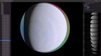
Hi All,
Finally got to the point that I have something cool to show. Still plenty more to do but I'm stoked at where I am. It's interactive, projected onto a sphere, and will display any image from any data set from the PDS archive. The rainbow in the back is the normal to help me be sure I'm putting the data in roughly the correct spot.
Couldn't have done it without your help. Thanks again!
|
Posted by: Sean Nov 5 2020, 06:24 PM
This is very cool. Beautiful work!
Posted by: Bill Dudney Nov 6 2020, 11:49 PM
Thanks!
It has been so much fun building this stuff
Is this you on twitter https://twitter.com/_TheSeaning? If so I love your work. It's a big part of what got me motivated to come back to this in my free time.
Posted by: Brian Swift Nov 9 2020, 06:00 AM
Definitely cool.
What is the development environment/toolset?
Posted by: Bill Dudney Nov 9 2020, 01:46 PM
What is the development environment/toolset?
Swift/Xcode/metal, runs on iOS, macOS and tvOS.
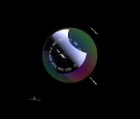
Posted by: Bill Dudney Jan 25 2021, 10:01 PM
Finally got to the point that I have something cool to show. Still plenty more to do but I'm stoked at where I am. It's interactive, projected onto a sphere, and will display any image from any data set from the PDS archive. The rainbow in the back is the normal to help me be sure I'm putting the data in roughly the correct spot.
Couldn't have done it without your help. Thanks again!
I finally had time to come back to this and get further along. Thought I'd share the latest UI. This is JNCE_2019202_21C00010_V01 from data set 12. Plenty more to do but good progress.
|
Powered by Invision Power Board (http://www.invisionboard.com)
© Invision Power Services (http://www.invisionpower.com)