MSL Images & Cameras, technical discussions of images, image processing and cameras |

  |
MSL Images & Cameras, technical discussions of images, image processing and cameras |
 Aug 25 2012, 11:29 AM Aug 25 2012, 11:29 AM
Post
#16
|
|||
 Senior Member  Group: Members Posts: 3648 Joined: 1-October 05 From: Croatia Member No.: 523 |
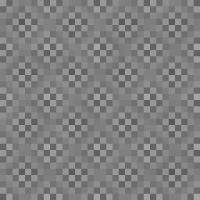
This is just for fun, I tried to implement an adaptive correction for the JPEGged (ugh!), raw Bayered images to get rid of artifacts in image areas that are smooth in appearance. The artifacts come from the JPEG algorithm trashing the Bayer pattern, introducing this kind of pattern:
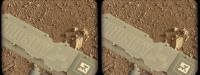
After correcting for that, the smooth areas became more smooth as illustrated by this comparison, although obviously this approach can't ever come close to an image already returned from the spacecraft in de-Bayered, color form:
I had to make the algorithm adaptive in picking which DCT blocks it will apply this to, because if I apply that correction invariably across the image, some uniform-color areas which originally already looked good had these artifacts introduced afterwards... -------------------- |
||
 |
 
|
||
|
Aug 25 2012, 06:32 PM
Post
#17
|
|||
 Member Group: Members Posts: 408 Joined: 3-August 05 Member No.: 453 |
Here is a poor man's way of de-Bayering Mastcam images using the Gimp (or similar tools) for those wanting to experiment a little - obviously not intended for the experts here! I realize it is not as sophisticated as proper implementations, but in the absence of a Gimp plugin, this way has the advantage of simplicity at the expense of ending up with a half-resolution image. It does not for instance use just the green pixels for luminosity, and it performs the chroma filtering by the simple expedient of scaling the image down by a factor of 2 (thus merging each set of red, blue and two green pixels together).
Airbag Bayer pattern color map image:
Sample result:
|
||
|
|
|
||
|
Aug 25 2012, 08:54 PM
Post
#18
|
||||
 Senior Member Group: Members Posts: 4256 Joined: 17-January 05 Member No.: 152 |
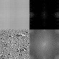
Here's the FFT of the jpeged Bayer patterns, upper two are a patch of smooth sky, and lower two a patch of ground:
In the ground image, you only see 2-pixel-scale (rough) periodicity, corresponding to the Bayer pattern, which shows up as broad peaks at the edges of the FFT. In the sky image, you also see peaks at the 2-pixel scale at the edges of the FFT, but sharp now since the sky is smooth. And you can also see FFT peaks halfway and quarter way to the edges, corresponding to 4- and 8-pixel periodicity. But of course there should be no 4 or 8 pixel periodicity in a smooth Bayer image! So clearly those peaks are the result of jpegging. So I tried to filter out those peaks in the power spectrum. Here's the result on the same image as ugordan used:
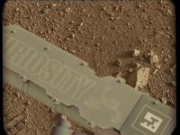
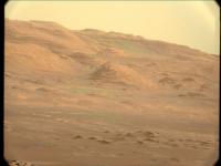
Very similar result! The Fourier space filtering beautifully gets rid of the blotchy pattern on large smooth areas, but breaks down at the edges of those areas since the periodicity breaks down there. But there was no need to make the algorithm adaptive here - it works in one simple step. Here's the horizon shot:
Again, a great job on the sky, but very little improvement on the not-so-periodic blotches over the mound. |
|||
|
|
|
|||
|
Aug 25 2012, 09:35 PM
Post
#19
|
|
|
Senior Member Group: Members Posts: 3516 Joined: 4-November 05 From: North Wales Member No.: 542 |
I'm totally fascinated by the various approaches to de-Bayering being tried out and discussed here, and that's from somebody not normally interested in the details of image processing techniques. I've learned a lot from the many posts, especially ugordan's and now fredk's. I love Airbag's slicing of the gordian knot for a quick short cut. Who says airbags are no use on this mission?
|
|
|
|
|
Aug 26 2012, 04:25 PM
Post
#20
|
|
|
Member Group: Members Posts: 122 Joined: 19-June 07 Member No.: 2455 |
I hope this is the right section for this. I'm actually replying to a post in another thread but, since it's about image processing, thought it better to put it here.
Amazing comparing the Hirise anaglyph to what we actually see on the ground. One thing that seems to be obvious to me though is that there is a real exaggeration of relief in the Hirise 3D effect (mesa are taller, canyons are deeper) most likely created because the left and right images are taken a great deal farther apart than the human eyes. If I understand they are simply images taken at different points in the orbit and not by two cameras side by side as on the rovers. While that relief is stunning and produces this amazing view of surface from above, it is not really a true representation as to what a human observer would see from orbit. In these days of phenomenal image and video processing software, where a program can build intermediate frames of a video by analyzing the pixels of each surrounding frame, I wonder if someone hasn't devised a way of correcting the relief of a 3D anaglyph if one knows the actual separation of the two images. I can certainly picture the code process in my mind and it doesn't seem complicated if one works with image comparison coding. I'm a computer programmer but it's been years since I did anything where I was manipulating pixels and my relearning curve would be extensive or I'd tackle something myself. Sure seems that anaglyphs have been around long enough that someone would have figured this out by now. Any thoughts? QUOTE (walfy @ Aug 26 2012, 02:21 AM)  I borrowed Fred's excellent rendition to compare with HiRISE anaglyph of the prime science region around the inverted riverbed. It's a very narrow angle of view. If I marked some features wrong, please let me know. [attachment=27716:msl_science_target.jpg] |
|
|
|
|
Aug 26 2012, 04:35 PM
Post
#21
|
|
|
Solar System Cartographer Group: Members Posts: 10226 Joined: 5-April 05 From: Canada Member No.: 227 |
I don't do anaglyphs so I can't get technical here, but basically the 3-D map created by a stereo pair can be displayed with any vertical exaggeration you like. Typically they are made with some exaggeration because most scenes are rather bland without it. For a given stereo pair there may be some default value that is normally used but it could be changed if desired.
Phil -------------------- ... because the Solar System ain't gonna map itself.
Also to be found posting similar content on https://mastodon.social/@PhilStooke Maps for download (free PDF: https://upload.wikimedia.org/wikipedia/comm...Cartography.pdf NOTE: everything created by me which I post on UMSF is considered to be in the public domain (NOT CC, public domain) |
|
|
|
|
Aug 26 2012, 05:09 PM
Post
#22
|
|
|
Senior Member Group: Members Posts: 3516 Joined: 4-November 05 From: North Wales Member No.: 542 |
QUOTE (Art Martin @ Aug 26 2012, 05:25 PM) I wonder if someone hasn't devised a way of correcting the relief of a 3D anaglyph We've discussed this here a while ago, but rather than try to dig back for that here are a couple of salient points. Anaglyphs don't have a constant intrinsic exaggeration factor. The apparent relief you see depends on the size of the image and the distance you view it from. Adjust those and you could in theory view any anaglyph without line-of sight exaggeration. It's true that in many cases you'd have to enlarge the image enormously and sit very close to it!! One solution I've suggested is the inclusion of a small virtual cube in the corner of each anaglyph to serve as a three dimensional scale bar, so if the cube looks too tall you know you're seeing the scene exaggerated by the same amount. |
|
|
|
|
Aug 26 2012, 05:17 PM
Post
#23
|
|
|
Senior Member Group: Members Posts: 4256 Joined: 17-January 05 Member No.: 152 |
I think what Art's suggesting is adjusting the apparent relief while keeping viewing size/distance constant. I could imagine doing that, for example by morphing one frame part ways towards the other to reduce relief. But that would be hard and would involve some degree of faking for the intermediate viewpoints.
For now, ngunn's approach can at least help reduce exagerated relief. |
|
|
|
|
Aug 26 2012, 05:55 PM
Post
#24
|
|
 Member Group: Members Posts: 706 Joined: 3-December 04 From: Boulder, Colorado, USA Member No.: 117 |
QUOTE (ngunn @ Aug 26 2012, 11:09 AM) It's true that in many cases you'd have to enlarge the image enormously and sit very close to it!! Actually, does enlarging the image have any effect on the apparent vertical exaggeration? I wouldn't expect so, because there should be no vertical exaggeration when the convergence angle of your eyes matches the convergence angle of the original image pair [convergence angle = angle between the two lines of sight in the stereo pair, measured at the surface location being viewed]. The convergence angle of your eyes depends on their distance from the image, but doesn't depend on the image magnification. John |
|
|
|
|
Aug 26 2012, 06:59 PM
Post
#25
|
||
 The Insider Group: Members Posts: 669 Joined: 3-May 04 Member No.: 73 |
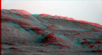
Here's my attempt at creating a 3d anaglyph image of the distant hills...
Attached thumbnail(s)
|
|
|
|
|
|
|
Aug 26 2012, 07:49 PM
Post
#26
|
|
|
Senior Member Group: Members Posts: 3516 Joined: 4-November 05 From: North Wales Member No.: 542 |
QUOTE (john_s @ Aug 26 2012, 06:55 PM) Actually, does enlarging the image have any effect on the apparent vertical exaggeration? I wouldn't expect so You are correct of course. It's the viewing distance alone that does it. I was confusing anaglyphs with cross-eyed pairs where the size does have an effect because it changes the angles too. QUOTE (Pando @ Aug 26 2012, 07:59 PM) Here's my attempt at creating a 3d anaglyph image of the distant hills. Excellent!  |
|
|
|
|
Aug 26 2012, 08:09 PM
Post
#27
|
|
|
Member Group: Members Posts: 122 Joined: 19-June 07 Member No.: 2455 |
Yes, that's exactly what I was wondering about. It would very much involve faking one of the images based on an analysis of an anaglyph created with the wider separation of views and then rebuilding the anaglyph with one original and the "faked" image. I guess derived image would be a more PC term much like when smoothing a video shot at low FPS and having the computer generate the intermediate images for a standard video frame rate based on a best guess of how motion and scaling would occur in each frame. When I've created anaglyphs in the past, the two original images are lined up vertically first and then the images are aligned horizontally for the most comfortable view. This results in a blue and a red tinted image combining both of the originals. When you view it without the glasses you can see distinct blue and red tinted objects with close up ones having more horizontal distance between those objects and the far away ones having very little distance or they're essentially right on top of one another. When the left and right image are taken at let's say hundreds of miles apart those distances get very exaggerated when viewed by human eyes. What the program would do would be figure out how much offset each pixel on let's say the right image shifted to the side from it's corresponding pixel on the left image and bring it back closer together in the proportion between a standard eye viewing angle and the actual image angles. I'd think that would be fairly easy to do on a long distant aerial shot but very tough on something close up because objects could block other ones from left to right. So guess this is a challenge to the programmers that have written the wonderful anaglyph software out there that pretty much assumes the original shots are taken at standard eye distance. They're already really doing the processing when they build the final red/blue image. You'd just need one more parameter in there that was the distance between the original images. Instead of simply combining the shots together, the blue portion would be derived and then combined.
One advantage of having this feature would be that you could also intentionally exaggerate the relief by creating the derived image at a much wider distance than it was originally shot to more readily spot depressions and things jutting up. QUOTE (fredk @ Aug 26 2012, 10:17 AM) I think what Art's suggesting is adjusting the apparent relief while keeping viewing size/distance constant. I could imagine doing that, for example by morphing one frame part ways towards the other to reduce relief. But that would be hard and would involve some degree of faking for the intermediate viewpoints. For now, ngunn's approach can at least help reduce exagerated relief. |
|
|
|
|
Aug 26 2012, 08:43 PM
Post
#28
|
|
 Senior Member Group: Admin Posts: 4763 Joined: 15-March 05 From: Glendale, AZ Member No.: 197 |
QUOTE (ugordan @ Aug 25 2012, 04:29 AM) This is just for fun, I tried to implement an adaptive correction for the JPEGged (ugh!), raw Bayered images Very ingenuitive thinking Gordan -- and it seems to have worked well. -------------------- If Occam had heard my theory, things would be very different now.
|
|
|
|
|
Aug 27 2012, 08:22 PM
Post
#29
|
|
|
Member Group: Members Posts: 122 Joined: 26-June 04 From: Austria Member No.: 89 |
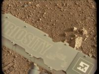
A few remarks about the near focus of the mastcams:
The pictures of the sundial taken by the mastcam-100 are not in focus up to now. I suspect that the near focus of this camera is a little bit beyond - for example the cable that running left of the dial is sharp: http://mars.jpl.nasa.gov/msl-raw-images/ms...1000E1_DXXX.jpg In contrast the m34 has taken sundial pictures that are in best focus: http://mars.jpl.nasa.gov/msl-raw-images/ms...0000E1_DXXX.jpg Did anyone know the distance from the mastcams to the dial ? Robert |
|
|
|
|
Aug 27 2012, 08:55 PM
Post
#30
|
|
|
Senior Member Group: Members Posts: 2542 Joined: 13-September 05 Member No.: 497 |
QUOTE (Roby72 @ Aug 27 2012, 01:22 PM) Did anyone know the distance from the mastcams to the dial ? The Marsdial is roughly 7.6 cm square and one side is 296 pixels long in the 34mm image. The IFOV of the 34mm is about 218 microrads, so the distance is roughly 1.2 meters. -------------------- Disclaimer: This post is based on public information only. Any opinions are my own.
|
|
|
|
|

|
Lo-Fi Version | Time is now: 22nd September 2024 - 03:19 AM |
|
RULES AND GUIDELINES Please read the Forum Rules and Guidelines before posting. IMAGE COPYRIGHT |
OPINIONS AND MODERATION Opinions expressed on UnmannedSpaceflight.com are those of the individual posters and do not necessarily reflect the opinions of UnmannedSpaceflight.com or The Planetary Society. The all-volunteer UnmannedSpaceflight.com moderation team is wholly independent of The Planetary Society. The Planetary Society has no influence over decisions made by the UnmannedSpaceflight.com moderators. |
SUPPORT THE FORUM Unmannedspaceflight.com is funded by the Planetary Society. Please consider supporting our work and many other projects by donating to the Society or becoming a member. |
|