Spirit's UnderBelly, processing the MI images |

  |
Spirit's UnderBelly, processing the MI images |
 Jun 28 2009, 06:07 PM Jun 28 2009, 06:07 PM
Post
#16
|
|
|
Member  Group: Members Posts: 688 Joined: 20-April 05 From: Sweden Member No.: 273 |
Is there any way to reduce the aperture external to the camera? There is unlikely to be any structure with a suitable pinhole to look through, but it might be possible to place the MI so that part of the aperture is blocked by the MER structure. Would this work? Most camera apertures become rather asymmetric at small apertures, but this does not seem to have much of an impact on the image quality.
|
 |
 
|
|
Jun 28 2009, 06:17 PM
Post
#17
|
|
 Senior Member Group: Members Posts: 3419 Joined: 9-February 04 From: Minneapolis, MN, USA Member No.: 15 |
Partially closing the MI's lens cap has been discussed here to achieve this, but as far as I know hasn't been tried.
-the other Doug -------------------- The trouble ain't that there is too many fools, but that the lightning ain't distributed right. -Mark Twain
|
|
|
|
|
Jun 28 2009, 08:00 PM
Post
#18
|
|
|
Member Group: Members Posts: 808 Joined: 10-October 06 From: Maynard Mass USA Member No.: 1241 |
Hey Other Doug,
Thanks for keeping me on the straight and narrow! Disclosure: My aperture/exposure time 'skills' come from an old manual 35mm Minolta that I haven't touched in years. Cheers -------------------- CLA CLL
|
|
|
|
|
Jun 29 2009, 03:12 AM
Post
#19
|
|
|
Member Group: Admin Posts: 976 Joined: 29-September 06 From: Pasadena, CA - USA Member No.: 1200 |
QUOTE (PDP8E @ Jun 28 2009, 12:00 PM)  ... Disclosure: My aperture/exposure time 'skills' come from an old manual 35mm Minolta that I haven't touched in years. ... I thought you meant that but was unsure. There are no iris on any of the cameras on board the vehicles. They are delicate mechanical devices that would be prone to malfunction. We can control the exposure time, the PANCAM have ND and bandpass filters, the MI has a lens cover, but that's it. No focus ring, no iris setting. Paolo (who recently traded his Nikon N6006 for a monopod) -------------------- Disclaimer: all opinions, ideas and information included here are my own,and should not be intended to represent opinion or policy of my employer.
|
|
|
|
|
Jun 30 2009, 02:41 AM
Post
#20
|
|||||
|
Member Group: Members Posts: 808 Joined: 10-October 06 From: Maynard Mass USA Member No.: 1241 |
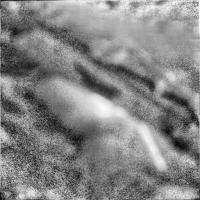
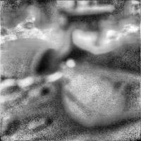
Here is the 1st peek under Spirit's deck taken a sol before the 'better' set
Same technique last image is in the next post
-------------------- CLA CLL
|
||||
|
|
|
||||
|
Jun 30 2009, 02:43 AM
Post
#21
|
||
|
Member Group: Members Posts: 808 Joined: 10-October 06 From: Maynard Mass USA Member No.: 1241 |
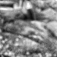
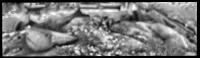
last image:
Cheers <Astro0 please do your mosaic magic !> -------------------- CLA CLL
|
|
|
|
|
|
|
Jun 30 2009, 12:26 PM
Post
#22
|
||
 Senior Member Group: Admin Posts: 3108 Joined: 21-December 05 From: Canberra, Australia Member No.: 615 |
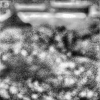
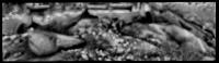
It's an interesting technique PDP8E, but I wonder how much more detail it is revealing to us.
Perhaps the 'smart contrast' should happen after the other processes. Here's the mosaic of your recent images.
|
|
|
|
|
|
|
Jun 30 2009, 02:24 PM
Post
#23
|
|
|
Member Group: Members Posts: 808 Joined: 10-October 06 From: Maynard Mass USA Member No.: 1241 |
Astro, first thanks for helping out with the mosaic! (I find it amazing that a guy in Boston can post a couple of images before bed, and then in the morning, find that another guy in Australia has added his technical and artistic expertise to the images...virtual collaboration!).
This little contrast trick only demonstrates one avenue of study on an image set that has many challenges (seriously out of focus, generally low light levels, very bright spots, extended light&dark areas -etc.). As can be seen, adaptive contrast enhancement balances on the hairy edge of introducing and using speckles (or as some would call it: noise!) as information I am attacking the focus problem at the moment (hitting the books), and hope to have something worth sharing in a little while. I hope the rover team gets little Spirit of this quagmire soon. Good luck with the sandbox Paolo! Cheers -------------------- CLA CLL
|
|
|
|
|
Jun 30 2009, 02:59 PM
Post
#24
|
|
|
Member Group: Members Posts: 104 Joined: 1-June 08 Member No.: 4172 |
For those who intend to do serious work on attacking the defocus, here are two documents which may come in useful, as they describe the technical and lens specifications for the Microscopic Imager. The toughest part is likely computing the proper PSF for each individual point on the image, as that would require knowledge of the exact distance to each pixel, which requires photogrammetric calculations that usually require a sharp stereo pair! The anaglyph may help, but an accurate mesh of the surroundings is somewhat of a goal and not available for input...one (crazy) option is an iterative bundle adjustment that starts with a good estimate for some sort of photometric textured mesh model for the situation and improves its estimate by repeatedly raytracing this model into images based on the camera parameters and checking how well they correspond to reality? Yes, I know this would probably require a couple supercomputers' worth of processing power and whatnot, but it might be worth a try...
PDS Instrument Record for MI Original Athena Paper describing MI |
|
|
|
|
Jul 1 2009, 04:27 AM
Post
#25
|
||
|
Member Group: Members Posts: 808 Joined: 10-October 06 From: Maynard Mass USA Member No.: 1241 |
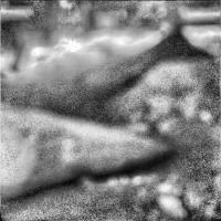
This is brief report on a work in progress: focusing of the MI images
The adaptive contrast was just an attempt to see in low light levels ... with varying success...depending on the quality of the input images. I cobbled together a focus program that takes some aspects of wavelets and the related least square methods. As a worst case input (but easiest for me) I used the processed mosaic (thanks Astro-naught) of JPL's 1st attempt to see beneath Spirit. After I finished the coding and debug, it ran 2 hours of CPU time (!) and deconvolved into utter ugliness. I ran it again and stopped it at iteration 211 (52 mins) and here is the result.
<little rock in the SW corner is better (and closer to the camera)...what is going on with the LM wheel?...> <a distant 'rock' seen through the (out of focus and) upside down 'U' of the hull, in the NW corner may be seen by the NAV/PAnN cameras for a check?> <can somebody get on their belly and take a series of pictures at the TEE BEE of the underside of the test rover? ...and post them?> The overall goal is to iteratively compute a new hi-res image and check it by producing a newer low res version, while comparing it to the actual low res (and then adjusting for the next iteration) -- I cheated and used 2 arrays -one each for a 1D representation of X and Y - rather than a more (days! worth of) complex matrix computations. (confession: averaging was used at the the intersections of pixels in the output array ~! ) Since this wost case image (super processed by me and then skillfully mosaiced by Astro0) 'looks' like it can be improved (?some what?.. you tell me...?) then, the next step: is to try this method on the original JPL original images, then contrast enhance, then mosaic. As a note, I can only detect one seam from the mosaic in the deconvolution...I thought I'd see them all. See you in a few days...? Cheers Ustrax: beautiful Tennyson poem...the Crew, Marines, and all of us caught up in this adventure hear you loud and clear... -------------------- CLA CLL
|
|
|
|
|
|
|

|
Lo-Fi Version | Time is now: 19th April 2024 - 07:47 PM |
|
RULES AND GUIDELINES Please read the Forum Rules and Guidelines before posting. IMAGE COPYRIGHT |
OPINIONS AND MODERATION Opinions expressed on UnmannedSpaceflight.com are those of the individual posters and do not necessarily reflect the opinions of UnmannedSpaceflight.com or The Planetary Society. The all-volunteer UnmannedSpaceflight.com moderation team is wholly independent of The Planetary Society. The Planetary Society has no influence over decisions made by the UnmannedSpaceflight.com moderators. |
SUPPORT THE FORUM Unmannedspaceflight.com is funded by the Planetary Society. Please consider supporting our work and many other projects by donating to the Society or becoming a member. |
|