Printable Version of Topic
Click here to view this topic in its original format
Unmanned Spaceflight.com _ Tech, General and Imagery _ Vignetting
Posted by: Tman Aug 24 2005, 07:37 AM
Hi Nirgal and all, I would like to discuss about vignetting and methods of resolution for it. I'm mainly interested in mathematical methods that could automatically calculate and adjust the right grey value for each pixel in a single picture.
My current method works with more or less transparent layers over the original picture that so roughly are able to balance the grey values. A perfect layer have to be the exact inverted brightness difference of each picture with this shadow effects. This method is very effective if you get the correct inverted values. These shots of the Mars sky come nearly at such a perfect mask, but not always. And of course the center of the pictures lose much of theirs original brightness/luminance sadly.
I have in mind a mathematical method that can adjust each grey value in a pic in order to obtain a completely balanced brightness over the entire picture. But I'm not in the position to reach that. I only know one have to start with the calculation of the grey values in the center of the picture. In the center are quasi the reference values of the whole picture, if I'm correct.
Is there a possibility (mathematical method) to get (roughly) the same brightness and luminance like in the center over the whole picture from the MERs?
Greetings, Peter
Posted by: Nirgal Aug 24 2005, 11:29 PM
Hi Tman,
mathematically, we can describe vignetting effects as a very low frequency
change in pixel brightness.
Unfortunately there is no "perfect" algorithm that could always distinguish the
Vignetting from other low frequency brightness variations that belong to the
"real" picture content and are therefore not to be canceled out.
So I'm afraid that there will be no better method than to use the
complete reference frames where the camera points to a uniformly bright sky.
So actually I think your method of using the Navcam reference sky-images is
already quite good !
The only problem that I can see is that the sky is probably not uniform and
that, if there is a time span between the reference image and the actual
shot, it may not work well because of intermediate changes n light conditions.
As for my "unstrip" program I had to choose a different approach, because it
is mainly intended to remove the dark "strips" (at the frame seams) in already stitched conplete panoramas.
The algorithm works as follows (simplified)
0. convert the image to LAB color space to handle color and luminance independently
1. try to find a *horizontal* strip in the image that is as uniform in brightness as possible.
2. apply a gaussian smoothing filter to each line of the reference area
3. "merge" step: calculate the reference line as an average of all lines in the reference area.
4. take the avreage brightness of the reference area as the reference luminance.
5. we now have our horizontal "brightness correcting curve", but it may still have
undesired high frquency variations (despite the smoothing)
6. so,as a last step I create a b-spline (or linear) interpolated version of the
correction curve.
7. apply the correction curve to each individual line in the image
(i.e. brightness(pixel(x,y)) = brightness(pixel(x,y)) + brightness(correction-curve(x))
Posted by: Tman Aug 25 2005, 11:26 AM
Hi Nirgal, probably you're right and it's impossible with Navcam pics. Btw. dont you fancy to dye my sol 581 pan again? 
Posted by: MichaelT Aug 25 2005, 12:42 PM
Hi Tman,
I tried it using "Fast Fourier Transformation (FFT)". For each row and each column of an image I calculated the FFT and took the lowest freqency to determine the amount of vignetting within that row/column. Then I averaged the results for the rows and the columns, seperately. That results in two vectors containing the average vignetting of the rows and the columns.
I used these two vectors to construct a template with the vignetting of the whole image. This template was then normalised yielding values between zero and one. After that I devided the original image by this template. By doing so, pixels with a value of zero remain zero, and the colour depth is preserved, actually increased. To compensate for that each image has to be transformed to pixel values between 0 and 255 afterwards.
That method gave quite some good results, but, there are some problems as well that I will have to follow up.
Michael
Posted by: Tman Aug 25 2005, 02:17 PM
Hi Michael, best we would talk about it in German, only the other members here would pull one's hair out (or so  ).
).
I dont know the FFT method so far, but it seems to be fundamental when programming high quality picture editing software. After a quick search in the web I found very interesting examples - but a.t.m. definitively too difficult to me.
Did you wrote a program for the FFT caculation that now works automatically when processing the MER pics?
My only hope is that you could programming a plug-in to PhotoShop with it 

When you get satisfactory results then, I would be the first customer!
Posted by: MichaelT Aug 25 2005, 04:39 PM
).Probably / Vielleicht
I think that my program works quite well now, though, you have to treat every image individually - not fully automatic, yet. Well, you only have to tune one parameter.
Here are some examples:
Sol 107, before and after anti-vignetting:


Sol 581 partial panorama (Autostitch):

Looks quite promising.
My only hope is that you could programming a plug-in to PhotoShop with it
When you get satisfactory results then, I would be the first customer!

Unfortunately, I use a data language called IDL, which is a commercial product and fairly expensive
 That's what we use at our institute. I wish I'd be able to write a Photoshop plug-in, but I am not
  If anybody else here would like to transfer this into another language, I could provide commented code.
Michael
ps: Ich schicke Dir gleich noch eine persönliche Nachricht auf Deinen Account.
Posted by: Nirgal Aug 25 2005, 05:16 PM
Looks quite promising.
Unfortunately, I use a data language called IDL, which is a commercial product and fairly expensive
That's what we use at our institute. I wish I'd be able to write a Photoshop plug-in, but I am not If anybody else here would like to transfer this into another language, I could provide commented code.Michael
ps: Ich schicke Dir gleich noch eine persönliche Nachricht auf Deinen Account.
Hi Micheal,
your approach sounds interesting: surely more involved than the ad-hoc method
I implemented in my "unstrip" program (I've just started to research vignetting problems and was very surprised that such a comparatively simple method
(even without FFT) could remove the "stripes" in multi-frame mosaics.


not perfect, but could be used for "cleaning" up existing panoramas without re-stitching ...
However, I'm interested in implementing your FFT-based method in the C language
(provided that it fits within my existing image processing libraries (FFT, etc)
so I could possibly provide a windows stand-alone program that anyone could use
as a simple command line utility...

Posted by: MichaelT Aug 25 2005, 05:59 PM
your approach sounds interesting: surely more involved than the ad-hoc method
I implemented in my "unstrip" program (I've just started to research vignetting problems and was very surprised that such a comparatively simple method
(even without FFT) could remove the "stripes" in multi-frame mosaics.
Yes, looks quite good already
(provided that it fits within my existing image processing libraries (FFT, etc)
so I could possibly provide a windows stand-alone program that anyone could use
as a simple command line utility...
Well, that sounds good
 I can prepare the comments tomorrow and post the program here tomorrow night.
Actually, I think that FFT is probably not necessary here either. Once a template function (f) is prepared, it could be used for all navcam images. Because the shape of the vignetting should only depend on the lense and not on illumination. Then, you only have to use f^n (n>0) for an image. Problem would be to determin n. That is a problem already now, because the FFT does not yield the perfect template function.
More about that tomorrow, got to leave

Michael
Posted by: Tman Aug 25 2005, 08:38 PM
Yeah sounds really good so far That would be fantastic if we could each single picture process so (roughly) good like your posted picture above Michael  - before any other processing. I guess (without any experience with this technology) that would really help to get nearly the best result in original luminance and details without any vignetting finally.
Posted by: Nirgal Aug 25 2005, 08:46 PM
Thanks Micheal,
hopefully I will find the time to do do the coding soon
(I'll never know whether I spent more time with image processing or with coding the tools that in turn help with the image processing
both is a lot of fun.. to see mathematics in action, turning formulas to
living shapes & colors
yes it's tempting, but in this case I think I'll probably wait for the full summit panorama
with all the multi-filter true color frames ... no need for artificial colors then
However I do plan a coloring of (part of) the sol 581 nacvam panorama
(in particular the scene with the large "dust-tornado", IMHO one of the all-time
greatest shots in space exploration at all !
Heck, even strom chasers on Earth would be proud of such a shot, showing
this F4-tornado sized monster within a mountain scenery...
but here we managed to capture this breathtaking moment on another planet !!
... what a beautifully convincing impression of a the "dynamic" nature of the
planet mars
... Oh, I'm getting carried away ...
... so unless we will catch a comparatively large & scenic DD also with the pancam I simply
have to somehow coloring this unbelievable view..
It will be difficult though, because the high amount of contrast stretching in this
series of pancam images (that leaves little play for manipulating the histogram) makes coloring process all the more difficult
(despite the fact, that there is only one "filter" to synthesize the colors from
Posted by: Tman Aug 25 2005, 09:29 PM
However I do plan a coloring of (part of) the sol 581 nacvam panorama
(in particular the scene with the large "dust-tornado", IMHO one of the all-time
greatest shots in space exploration at all !...
Maybe it shows some artifacts, but it is also simply a very nice matter of Mars artwork to me! It looks partly like a real and high-quality canvas!
Guess I'll this sol 581 Navcam pan still complete to a 360 degree full res. pan - but so far in a left pic lack two parts. It would be nice to see the whole scene with all the features and DDs around and always coming back to the monster DD.
I mean too this scene is quite special.
Posted by: Tesheiner Aug 26 2005, 06:42 AM
Tman,
Try the right (R0) channel; it is already complete.
Posted by: MichaelT Aug 26 2005, 05:57 PM
Nirgal, I finished the commenting of my program to eliminate the vignetting. It is now fully automatic. You, or anybody else who is interested, can download it from http://www.muk.uni-hannover.de/~theusner/mars/vignett_fft.pro.
I hope that you can find your way through the code. If you have any questions, just ask me. Or, if you want to know how some of the IDL-routines work, you can have a look here: http://idlastro.gsfc.nasa.gov/idl_html_help/idl_alph.html
The program can deal with jpeg-images only which have equal x- and y-dimensions. Currently, it needs true color images. Basically, it gets along with all MER images.
I also have ready a simple graphical user interface which can be run by everyone after downloading RSI's IDL Virtual Machine, which is for free (or without VM if you already have IDL on your computer).
http://www.rsinc.com/idlvm/
It uses pre-complied IDL-programs. So, if anybody is interested, you can download the pre-compiled GUI http://www.muk.uni-hannover.de/~theusner/mars/anti_vig.sav.
It looks like this:
Please drop me a line if you use the program or if you find any bugs while using it.
Michael
Posted by: MichaelT Sep 14 2005, 05:49 PM
I have now modified the anti-vignetting-program (using IDL) such that it can deal with any kind of jpeg-image. Also, it does not use FFT any longer but simply takes a 2D-cosine-shaped mask. That mask is fitted to the chosen image and the amount of vignetting automatically determined (that can be done RGB-channel specific). It also allows to save images as 16-bit-tiff so that none of the original information is lost in the out-put image. You can also do manual adjustments if the amount of vignetting is over- or underestimated by the program (depends on the structure of the image). All that has to be done with each single image and cannot be aplied to a ready panorama.
Below are two examples (SOL 582).
Without anit-vignetting:
After anti-vignetting:
After anti-vignetting the sky shows a very even color distribution, without these nasty green edges. These are obviously due to different amounts of vignetting in the RGB-channels.
I also tested that program with scanned slides and digital camera images and it works very well. So it does not only work with martian craters but also with terrestrial ones The image below shows Wolfe Creek meteorite crater in Western Australia. Its got a diameter of 850 m and is about 30-40 meters deep. Like martian craters it is filled with sand and dust (80 meters).
Panorama from three frames.
The only draw-back is that I cannot provide a stand-alone version of that program  Though, http://www.muk.uni-hannover.de/~theusner/mars/anti_vig.sav can be run with http://www.rsinc.com/idlvm/index.asp. It's free, but requires registering and is a 115 MB download
Is there anybody here who's got a license to turn this IDL-program into a stand-alone one?
Michael
Posted by: dilo Sep 14 2005, 06:38 PM
WOW!
MichaelT, I think would be really GREAT to implement your algorithm inside MMB... I would know opinion from the other Michael on this item...
Posted by: Bob Shaw Sep 14 2005, 06:53 PM
MichaelT:
Do you think your anti-vignetting app could be tweaked to sort out the tone variations seen across the Surveyor frames?
Bob Shaw
Posted by: djellison Sep 14 2005, 07:03 PM
I'm guessing there's no flatfield or darkfield for the Surveyor stuff ( where can you get it all anyway?)
If you took all the surveyor frames that didnt include the 'sky' and averaged them, you might get an appropriate 'flat field' - which you could then invert, and overlay at a few percent opacity on all the other frames.
Doug
Posted by: tedstryk Sep 14 2005, 07:32 PM
I usually try to make a blank image with my digital camera to record only the vignetting so that it can be subtracted. Here are some pans where it works well. Sometimes it works, sometimes it doesn't. To do this automatically would be great!


Posted by: MichaelT Sep 14 2005, 07:39 PM
Do you think your anti-vignetting app could be tweaked to sort out the tone variations seen across the Surveyor frames?
Bob Shaw
Bob, have you got one for me to try it out? At the moment I don't quite know what those images look like. These tone variation would have to be roughly rotation-symmetric to eliminate them. I could also change it that way that it uses some polynomial fitting functions. Then it might work with non-rotation-symmetric variations, too.
Michael
Posted by: Bob Shaw Sep 14 2005, 08:43 PM
Michael
MichaelT:
I can scan a couple, and will post them here, and will also have a look at some WWW locations. Nothing will be particularly clever in terms of quality (ask Phil Stooke, he's got a lot of more-or-less first generation-ish scans which he's used for some of his Surveyor panoramas).
Oh, and on further thought, what about automating Lunar Orbiter image drop-offs, or Mariner 6/7 ghost images, or...
...look what you started!
Bob Shaw
Posted by: MichaelT Oct 24 2005, 04:30 PM
Hi,
I put an updated version of the anti-vignetting program online. I corrected some minor errors and it now supports output as 16-bit-TIFF. That way one can do all the adjusting after the anti-vignetting process wihtout loosing any information. As usual it is a precompiled IDL-program and can be used with RSI's Virtual Machine (see earlier posts).
You can find the program here: http://www.muk.uni-hannover.de/~theusner/mars/anti_vig.sav
Tman pointed me to the fact that some people are already using that program, and the results really look nice. As I was in the final stages of PhD-thesis-writing until mid-October, I had not noticed that so far But now I am done
Anyway, I would not mind input from the users. Is there something that you would like to be improved?
Bob: Did you scan any images so far?
Michael
Posted by: jvandriel Nov 1 2005, 10:31 AM
Tman,
what I mean to say with those lines is the following:
Anti-vignetting of Navcam images gives around 20% better images and Pancam images
around 3 or 4% better images. ( see the percentage after vignetting. )
The end result of every image after anti-vignetting with MichaelT's program is much better, as you describe.
Therefore I use the anti-vignetting program for Navcam and Pancam images for every
panoramic view I make.
jvandriel
Posted by: Tman Nov 1 2005, 11:59 AM
You're right Jvandriel, it's for both very helpful. If one use them without automatical brightness/color correction during the stitching process, especial with PTGui's "PhotoShop with feathur" version, one mostly have only to correct a brightness gradient that caused by the sun direction during the shot (among the correction of exposure). I overcome this rest gradient with an adjusted mask over each frame.
"those lines" adress my post here, right: http://www.unmannedspaceflight.com/index.php?showtopic=1506&view=findpost&p=25066
Posted by: Tesheiner Nov 1 2005, 02:25 PM
Michael, consider this as a letter to Santa Claus...

"I want a standalone version without IDL dependency".
Posted by: djellison Nov 1 2005, 04:00 PM
I dont mind it running in IDL, but I would really like a batch processing tool.
Doug
Posted by: MichaelT Nov 1 2005, 04:22 PM
Doug
Ok, that is something that I had in mind, too. I will implement a button to do batch processing soon.
"I want a standalone version without IDL dependency".
Unfortunately, I do not have the ability to convert the program into a stand-alone version. The necessary IDL packages are quite expensive and the uni institute that I am working at did not buy them for that reason
If there is anybody who could help me with that problem, please tell me.
Michael
Posted by: MichaelT Nov 1 2005, 05:45 PM
I just put online Version 2.0, now with batch processing option ('batch' button). You can do the vignetting settings before choosing the batch option (eg. with a template image). The settings will then be applied to all the selected images. You can also select vertical parts of the image (eg. the sky, see 'Help') that will be used to determine the amount of vignetting. That selection will the be used for all batch images.
So far, the images will be generated in the folder where the files are located. That will be changed in a future version. An 'av' is added to the files to prevent overwriting of the original images.
http://www.muk.uni-hannover.de/~theusner/mars/anti_vig.sav
Let me know if there are any problems.
Michael
Posted by: Tman Nov 1 2005, 06:58 PM
Hi Michael,
Tried the batch processing just with the last Spirit's sol 649 Pancam files which I used for a pan and it works very well so far.
Thanks!
Very helpful to last the fastest MER-pans producer forum of the world.
Posted by: jvandriel Nov 3 2005, 03:20 PM
Michael T,
today I used for the first time your anti-vignetting program with the batch processing addition. ( V 2.0 )
It works great. No problems at all.
jvandriel
Posted by: Nix Nov 3 2005, 07:12 PM
I'm starting to use your tool too, looks pretty good !
Thanks
Nico
Posted by: mhoward Nov 11 2005, 04:09 PM
MichaelT, I think would be really GREAT to implement your algorithm inside MMB... I would know opinion from the other Michael on this item...
If there were a Java version of this algorithm, it might be possible to put it into MMB. It would be neat to have Navcam mmbpans with anti-vignetted images. Since MMB is open-source now somebody else could work on this as well.
Posted by: dilo Nov 13 2005, 08:02 AM
This is a very important item, I already suggested to implement anti-vignetting in MMB some time ago!
I do not know Opens Source / Java, hope some expert volunteer will work on this.
Apart the advantage for perfect stitching, not only NavCam will improve. Biggest single-image benefits would be on hazcam, as showed in the following example from Sol639 Opportunity (I made also some image processing in addition to anti-vignetting, now I wonder how much information can be recovered from extreme-conditions images like this!)
|
Posted by: MichaelT Nov 13 2005, 06:17 PM
Hi Michael,
it would indeed be very nice if someone implemented it into MMB. Unfortunately, that won't be me as I do not have experience in Java-programming. I will post the code of my anti-vignetting routine in the next couple of days. So I hope that someone else can transform the code into Java.
Michael
Posted by: jaredGalen Nov 13 2005, 06:49 PM
I would be interested in giving it a go. I made a java attempt at MichaelT's
DD enhancing algorithm before so I fancy a go at this even of some else beats me to it
But I think I might need a bit of expansion on parts of the algorithm posted at the start of the thread.
I'm not entirely sure of the different colour spaces.
For example can you convert directly from greyscale to LAB or must it be in RGB.
I have been looking and have found conversion from RGB to XYZ to LAB but not directly
from RGB to LAB.
>>0. convert the image to LAB color space to handle color and luminance independently
And then
>>6. so,as a last step I create a b-spline (or linear) interpolated version of the
correction curve.
In terms of getting the curve and things I'm a bit 
I'll wait for MichaelT to post his routine I think, but I'll give it a go.
Posted by: MichaelT Nov 14 2005, 06:12 PM
DD enhancing algorithm before so I fancy a go at this even of some else beats me to it
But I think I might need a bit of expansion on parts of the algorithm posted at the start of the thread.
I'm not entirely sure of the different colour spaces.
For example can you convert directly from greyscale to LAB or must it be in RGB.
I have been looking and have found conversion from RGB to XYZ to LAB but not directly
from RGB to LAB.
>>0. convert the image to LAB color space to handle color and luminance independently
And then
>>6. so,as a last step I create a b-spline (or linear) interpolated version of the
correction curve.
In terms of getting the curve and things I'm a bit
I'll wait for MichaelT to post his routine I think, but I'll give it a go.
Ok, its great that you want to try it
I hope you find the following lines useful. By now I completely skipped using FFT . It can just as well be done without.Concerning LAB etc: I don't know how to convert between the different color spaces. I found that the amount of vignetting in the color images is different between the RGB channels. So I don't know what it would be like if you applied the anti-vignetting to the two color-channels of LAB. Probably that gives some strange results? Don't know.
The other questions are hopefully answered below:
These lines of code are to generate the template function (see below).
First a vector T is generated that is XDIM long (XDIM: the x-dimension of the image) and runs from -pi/2 to +pi/2. The FINDGEN command outputs a vector of length XDIM containing values in ascending order from 0 to XDIM - 1.
EM = COS(T) * 0.1 + 0.9 is used as basis for the template matrix. As you can see it has a cosine shape. As initial value of the vignetting I assume 10%, ie. the factor 0.1. The 0.9 is added so that the maximum value is 1.0 while the minimum is 10% lower.
This vector is filled in a matrix of size (XDIM, XDIM) if XDIM > YDIM otherwise YDIM is used (IF statement).
To obtain a rotation-symmetric matrix, the transpose is added to that matrix and everything devided by two (ES).
To match the size of the image, the unneccessary data are removed (ESS).
To save time, the template is later fitted to a size-reduced image, and, therefore, reduced to the given size using the CONGRID-command. The size then is (512, YDIM*512/XDIM) or (XDIM*512/YDIM, 512) depending on the image (landscape or portrait).
[code begins]
IF XDIM GE YDIM THEN BEGIN
DISX = 512.0
DISY = YDIM * 512.0 / XDIM
T = (FINDGEN(XDIM) * 1.0 * !PI / XDIM -!PI / 2.0)
EM = COS(T) * 0.1 + 0.9
ES1 = {ES11: EM}
ES1 = REPLICATE(ES1, XDIM)
ES = (ES1.ES11 + TRANSPOSE(ES1.ES11)) / 2.0
ESS = ES[*, DIFF: DIFF + YDIM - 1]
ESS2 = CONGRID(ES[*, DIFF: DIFF + YDIM - 1], DISX, DISY)
ENDIF ELSE BEGIN
DISX = XDIM * 512.0 / YDIM
DISY = 512.0
T = (FINDGEN(YDIM) * 1.0 * !PI / YDIM -!PI / 2.0)
EM = COS(T) * 0.1 + 0.9
ES1 = {ES11: EM}
ES1 = REPLICATE(ES1, YDIM)
ES = (ES1.ES11 + TRANSPOSE(ES1.ES11)) / 2.0
ESS = ES[DIFF: DIFF + XDIM - 1, *]
ESS2 = CONGRID(ES[DIFF: DIFF + XDIM - 1, *], DISX, DISY)
ENDELSE
[code ends]
No comes the routine to fit the template to the image. It is rather complicated...
Using an iterative process I try to get as close as possible to the optimal fit. There are likely quicker/better ways to do this.
Firstly, ESS2, the template (see above) is now called E. The aim is to determin a parameter NR so that E^NR optimally fits the image.
First I calculate E^NR for three preset values given in INTR, yielding ESSR. Then I divde the image ( B ) by ESSR, which results in a temporary vignetting reduced image (FP_TEMP_R).
In step two I run through all rows (chosen by the user, actually rows between APY1 and APY2. That allows to do the fitting for parts of the image, eg. the sky, only) of FP_TEMP_R and fit a 2nd-order polynomial to the pixel-values (X is there to provide some x-values for the fit). The parameters of which are stored in RR. If an image is completely without vignetting, I assume that the sum PTR of the squared 2nd-order parameters (RR[2]) is minimal, as the "curvature" of the pixel values caused by the vignetting should be gone.
You might ask now, why I fit a 2nd-order polynomial to the supposed cosine shaped vignetting. Well, I found that the difference is not that large in most cases and that there are ready-to-use IDL routines for the polynomial fit.
As you can see I do this for the three values given in INTR [I1, I2, I3],. After doing so, I look for which of the two values PTR is minimal. I then use these two values from INTR (would be either [I1, I2] or [I2, I3])to define a new INTR with three new values. Two of which are I1 and I2 or I2 and I3 and a value in between the two (actually not quite I1, I2 or I2, I3 as the optimal value might still be in the respective other interval, but close to I2). The whole process then starts again with these new values. That is done a total of 15 times. After that the interval INTR has converged sufficiently close to the optimal value of NR.
[code begins]
E = ESS2
INTR = [0.0D, 15.0D, 30.0D]
X = DINDGEN(DISX) - DISX / 2.0D + 0.5D
RR = FLTARR(3, DISY)
RTR = FLTARR(3)
FOR K = 0, 14 DO BEGIN
FOR J = 0, 2 DO BEGIN
ESSR = E^INTR[J]
FP_TEMP_R = B / ESSR
FOR I = APY1, APY2 - 1, 1 DO BEGIN
WAIT, 0.00001
RR[*, I] = POLY_FIT(X, FP_TEMP_R[*, I], 2)
ENDFOR
RTR[J] = TOTAL(SQRT(RR[2, *]^2))
ENDFOR
SRTR = SORT(ABS(RTR))
INTR = [INTR[SRTR[0]], (INTR[SRTR[0]]+INTR[SRTR[1]]) / 2.0D, INTR[SRTR[1]]]
INTR = INTR[SORT(INTR)]
INTR = [INTR[0] - 0.05D * (INTR[1] - INTR[0]), INTR[1], INTR[2] + 0.05D * (INTR[2] - INTR[1])]
ENDFOR
[code ends]
All that can be done for all three color channels, as the amount of vignetting can be different for red, green and blue. Not for gray-scale images, though.
The code below shows what would be done for a gray-scale jpeg after NR (actually the parameter for the red-channel) has been determined:
[code begins]
NR = INTR[SRTR[0]]
NG = NR
NB = NR
ESST = ESS^NR
CR = CRS / ESST
CG = CGS / ESST
CB = CBS / ESST
[code ends]
Where CRS, CGS and CBS are the original color channels of the image. The new ones are CR, CG and CB.
In my program you can additionally choose howstrong the anti-vignetting is applied, so the final result would by something like:
CR = AV * CRS / ESST + (1 - AV) * CRS
etc., with AV between 0 and 1 (actually AV< 1 would be/is possible).
But I think this part is the most interesting for you jaredGalen. Most important is, I think, that the determination of the amount of vignetting can be done with a size reduced image. The found parameter can then be used for the original image. That saves a lot of time
The complete program can be found http://www.muk.uni-hannover.de/~theusner/mars/anti_vig_comm.pro
Unfortunately, I did not have time to comment it very much. I know, this is bad
Any other questions
Michael
Posted by: jaredGalen Nov 14 2005, 06:33 PM
Wow, okay.
Looks like I have my work cut out for me.
Cripes, I'll have to pour over what you have said and your code first before I go
asking more questions. The color space issue is concerning me a little but I'll leave
that til I have a metter understanding of what you do.
I have a feeling I will have plenty of questions.
If anyone else outhere is thinking of doing this then by all means drop in.
Edit: Just realised the algorithm I was looking at originally wasn't posted by Michael. Muppetesque moment for me . That clears a few things up. Sorry about that.
Don't worry. I have everything under control
Posted by: slinted Nov 14 2005, 11:15 PM
Michael, thank you for sharing the code to this application. I've found the program very useful, and look forward to digging into its inner workings a bit deeper.
Jared, since vignetting is a camera effect, I'm pretty sure it would be inappropriate to use this application in Lab space. The L channel is shaped similar to a cube root function as it is intended to be a perceptive measure of brightness, and is therefore not linear with photon count like the raw images (well, in a perfect world at least . This means the 'fit' used to determine the amount of vignetting would be even more complicated if you used L instead of the actual pixel brightness through a given filter. The ab parameters concern themselves only with the ratio between color channels (or in MERs case, the raw images) and the only way to know if you have accurately described those would be to use this on the raw images before determining the color at each pixel.
Posted by: jamescanvin Nov 15 2005, 02:50 AM
How long does this program take to run for you guys?
I got it running on my Mac yesterday but it takes 4 - 5 mins on each raw pancam frame! I know it is a complicated procedure and it's running through a virtual machine so it's not going to be instantaneous but my activity monitor says it's only using about 10% of my CPU.
Just wondering...
James
Posted by: jaredGalen Nov 15 2005, 09:05 AM
Thanks for the advice, the Lab color space thing got into my head from an earlier
post in this thread that I though was connected to the current version of michaels app. I realise now I can totally ignore it.
Thankfully, didn't like where it lead me
I will have few questions, have to wait till tonight though.
Posted by: MichaelT Nov 15 2005, 10:04 AM
I got it running on my Mac yesterday but it takes 4 - 5 mins on each raw pancam frame! I know it is a complicated procedure and it's running through a virtual machine so it's not going to be instantaneous but my activity monitor says it's only using about 10% of my CPU.
Just wondering...
James
Thats really a long time

I have a 2.8 GHz Windows PC (512 MB ram) and it usually takes about 5 seconds to process one image, using the virtual machine...
What about the other users? How long does it take you to get one image done?
Michael
Posted by: Tman Nov 15 2005, 10:51 AM
The same to me - 5 seconds.
My PC system runs 2,4 GHz Pentium© 4
That's most probably not a rate of calculation problem.
Posted by: jamescanvin Nov 15 2005, 01:34 PM
Hmm, 5 seconds eh, that's a bit quicker than 5 mins!
Anybody else got this working on a Mac?
Posted by: Nix Nov 15 2005, 05:28 PM
no mac, but 3 seconds, although it might well be a bit slower in a batch.
so yes, 5 mins is
Hope you figure it out.
Nico
Posted by: jamescanvin Nov 15 2005, 11:13 PM
I hope so too!
At least it works though. And I can always just leave it running in the background all day on batch mode. Alternately I can always run multiple versions to get it using a bit more of my CPU (further to saying it was using 10% before, I watched it in Activity monitor and most of the time it's at no more than 3%!)
My Mac is technically owned by the university who have an IDL site licence so I might just get the real thing installed and try that. Or just run it at work on Linux. Lots of options it's sure not going to stop me making pans, I've only just got the hang of it!
James
Posted by: MichaelT Nov 16 2005, 08:47 AM
I made a minor modification to the program. I don't know whether that will make any difference to the problem that you encountered James. Just try it out and tell me what the result is. Version 2.0.1 can be found here: http://www.muk.uni-hannover.de/~theusner/mars/anti_vig.sav
Michael
Posted by: jaredGalen Nov 16 2005, 01:38 PM
Hi, I haven't a much of a chance to do any coding yet.
I just want to clarify something.
MichaelT, the CONGRID command you use. I have to implement that myself but
I want to check that all I have to do is take a two-dimensional array and
subsample it down to the smaller size.
Hopefully over the weekend I'll get a chance to get something done. After the Ireland v Australia rugby match of course.
Posted by: MichaelT Nov 16 2005, 03:12 PM
I just want to clarify something.
MichaelT, the CONGRID command you use. I have to implement that myself but
I want to check that all I have to do is take a two-dimensional array and
subsample it down to the smaller size.
Yep, that's it
Talking about Australia:
The Socceroos just made it to the World Cup in Germany next year by beating Uruguay 4-2 on penalty shoot-out.
And I used to watch rugby, too, when I lived in Hobart in 1999/2000.
Unfortunately, its impossible to watch it here.Michael
Posted by: Nirgal Nov 16 2005, 08:36 PM
Micheal,
I just like to say thank you for sharing your software !
As you know, I was already in the process of developing my own anti-vignetting software, implementing a similar algorithm in C,
but with the latest version of your program (with the batch mode !)
there is no need for an own AV-tool any more :-)
The only advantage of a C-based program (that I originally planned to write)
would be speed and the potential to run without additional virtual machine ... but I have downloaded and installed the IDL and it's fast enough and without hazzle and really no problem at all ... Plus: your program has the fine graphical user interface whereas most of my C-based tools are rather cryptic and mostly command line driven .. although I really would miss batch capabilities ...
So I think your latest batch-enabled version of AntiVig will definitely become the "gold standard" of Anti-Vignette processing in the MER imaging community
Thanks again !
Posted by: jamescanvin Nov 17 2005, 03:10 AM
Michael
Will do, thanks Michael,
will be over the weekend however, v-busy today/tomorrow.
James
Posted by: MichaelT Nov 17 2005, 08:45 PM
I just like to say thank you for sharing your software !
[...]
You're welcome and thanks for the nice words
Michael
Posted by: jvandriel Nov 18 2005, 12:41 PM
MichaelT,
I just downloaded Anti_Vig 2.0.1, but when I try to use it I get the following message:
"Attempt to call undefined procedure/function: Anti_Vig 2.0.1 ".
Version 2.0 works fine.
jvandriel
Posted by: Tman Nov 18 2005, 01:44 PM
Hi Jvandriel,
I guess you renamed it as "Anti_Vig 2.0.1", right?
But it's necessary to keep the name of the program only "anti_vig.sav"
I tried that already too.
Posted by: MichaelT Nov 18 2005, 01:49 PM
I just downloaded Anti_Vig 2.0.1, but when I try to use it I get the following message:
"Attempt to call undefined procedure/function: Anti_Vig 2.0.1 ".
Version 2.0 works fine.
jvandriel
That is strange.
I just downloaded it and run it with VM - no problems...
When does that error occur? Already on start-up?
Just to be on the safe side, I re-compiled the program and http://www.muk.uni-hannover.de/~theusner/mars/anti_vig.sav. It's version 2.0.2.
Michael
Posted by: MichaelT Nov 18 2005, 01:54 PM
I guess you renamed it "Anti_Vig 2.0.1", right?
But it's necessary to keep the name of the program only "anti_vig.sav"
I tried that already too.
You are right Tman!!!
I should have noticed that from the error message.
It is absolutely necessary to leave the name of the file as it is. Because that is what is stated in the first line of the program: its name. And that can't be changed by you.
Michael
Posted by: MichaelT Nov 18 2005, 02:04 PM
Would you like me to include the version number in the name of the file? Wouldn't be a problem. So you could keep all the old versions in one folder and use them independently.
Michael
Posted by: Tman Nov 18 2005, 02:09 PM
Hi Michael, just reply overlap.
Regarding version number in the name, I would like it. So one can leave the previous version just in the same file folder - I know it is not necessary but I always keep the previous for safeness.
Posted by: jamescanvin Nov 19 2005, 02:43 AM
Michael
It works!
Thanks Michael,
Cheers, James
Posted by: MichaelT Nov 19 2005, 08:05 AM
Thanks Michael,
Cheers, James
Well, I had forgotten to eliminate one little command: WAIT, 0.00001
That command makes the program wait for 1/10000 of a second.
I had to slow down the program on my comupter on purpose, when running in IDL. Otherwise it always crashed, probably due to some ram access conflicts. That wait-command is within a loop, resulting, theoretically, and on a Windows system obviously practically, in an overall delay of about 1/200 of a second. Why that causes the program to be that slow on a Mac is quite surprising. Sorry for that. In the end, all I had to do was to delete these lines. You can still find them in the code that I posted further above.
Have a nice weekend!
Michael
Posted by: jvandriel Nov 19 2005, 02:04 PM
MichaelT and Tman,
thanks for the advice. I did indeed change the name.
Now I have downloaded Version 2.0.2 and it works perfect. ( without changing the name of course. )
MichaelT,
is it possible for you to make the following modification to your program.
Now, in batch processing mode, every image is calculated and saved.
It is not possible to individual change the brightness of an image. That must bo done later by hand.
For example,
in batchmode after calculating the image the batchmode halt, then change the brightness by hand, ok it and the batchmode continue and saves the image, calculate the next image and halt for brightness change and so on and so on until all the images are done.
Sorry, to give you more work.
jvandriel
Posted by: MichaelT Nov 24 2005, 05:40 PM
Now, in batch processing mode, every image is calculated and saved.
It is not possible to individual change the brightness of an image. That must bo done later by hand.
For example,
in batchmode after calculating the image the batchmode halt, then change the brightness by hand, ok it and the batchmode continue and saves the image, calculate the next image and halt for brightness change and so on and so on until all the images are done.
Sorry, to give you more work.
jvandriel
I thought about these things already, too. They require some major modifications to the program.
Unfortunately, I have very, very limited time at the moment which does not allow me to tackle that task. Also, I will be away from mid December until mid January. I will not be able to answer requests during that period.
I wish I had more time for these things now as they are a lot of fun. But I have to put you off until next year.
But I promise to do it.
Michael
Posted by: MichaelT May 5 2006, 11:46 AM
After a long, long time I am currently developing a new version of my anti vignetting tool, version 3. Again, it is based on IDL and can be used with RSI's Virtual Machine. See http://www.unmannedspaceflight.com/index.php?s=&showtopic=1306&view=findpost&p=18469.
It is not complete, yet. The "save file" buttons are not fully functional up to now (you can't save). But, I want to give you a preview of what to expect during the next weeks. You can already play around and test it and tell me about any bugs that you find.
The program is now faster due to a much improved and simpler de-vignetting routine. Also, you can do more adjustments than in the previous versions.
Other improvements:
- You can open as many files as you like and change between them during processing (pull-down-menu).
- A '+' or '-' before each file name indicates the processing state (with or without de-vignetting).
- After processing simply choose "save all" and the program will automatically save all the files in folders designated by you.
- "Save all" will open a window with a list of all files and their current state of processing. It is planned to enable you to set output-folders for each file or copy a certain output-folder-name to a selection of files. After hitting "save", all currently processes images will be saved one after another. This could take some time as the program does not keep the whole file in its memory but just a smaller version. So it will read each file again, do the de-vignetting and save it to the destination folder.
- Like in the previous versions you can choose either jpeg or 16-bit-tiff output (or both). Do you need any other file types (png)?
- You can draw an area in the image window which will be used for the de-vignetting (by clicking with the left mouse button, set up to 64 points). Clicking close to an already present line will insert a new point. These points can be relocated by holding the left mouse button and moving the mouse. You can delete them by double-clicking (except the one in the lower left corner).
- The selcted area can be copied from one image to another.
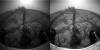
- The de-vignetting of anaglyphs also removes the green/blue - red gradient wich often causes dark borders between image even though they vignetting has been removed.
- You can also adjust the brightness of the image (shift the whole color range or with a multiplicative factor) and the amount of vignetting.
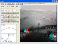
- Clicking and holding with the right mouse button will show the unprocessed image if you have already processed it. This click will also select a line (x direction) the brightness values of which will be shown in the left hand window when changing the brightness and de-vignetting settings. That way you can optimally adjust the a-vig values.
- The histogram of the image is also shown after each change. Even though the image is shown with a pixel value cut-off of 255 then actual histogram is shown in the histogram window. Saving the file as 16-bit-Tiff will retain even those pixels which are brighter than 255.
- Moving the mouse cursor over a button will show you its function (help button is still missing).
- you can choose the type of the image (gray-scale, anaglyph, RGB) manually, though it is determined automatically when loading it. Changing the type can have the benefit that you can move the sliders for the de-vignetting and brightnes adjustment either independently or together. before saving you should set it back to the actual type.
Things I also want to implement is output of the de-vignetting or vignetting mask.
There are certainly things that I forgot to mention. Simply try it out or ask me.
So this is the time now to tell me your wishes or worries or both
The program is located here: http://www.muk.uni-hannover.de/~theusner/mars/anti_vig_n.sav
Like in the previous versions, you must not, under all circumstances, change its name
Have fun playing around with it!
Michael
|
Posted by: hortonheardawho Jun 9 2006, 10:16 PM
Hi Michael,
I have been interested in your anti-vignetting program for some time -- but have resisted the HUGE ( 118 MB ) download of IDL6.3 VM.
Well, I just downloaded the VM and your new version -- but before I run the VM install I want to understand the implications.
How does the IDL VM interact with the O/S -- specifically Windows 2000?
Requirements? I am running a Pentium 4 @ 1.5 GHz with 768 MB of memory. I am a little short of disk space on C ( down to my last few GB ) but have about a 100GB free on D.
Looking forward to producing some "professional looking" panoramas utilizing your tool.
color by horticolor: more real than real.
Posted by: hortonheardawho Jun 11 2006, 07:58 PM
Doesn't look like Michael is monitoring this thread anymore.
I tried antivig 2.0.2 -- worked great!
Here is my first antivig panorama:
http://www.flickr.com/photos/hortonheardawho/165067263/
tried the new version -- looks like some interesting features -- but the saves -- don't.
Anyway, I will use the tool for future pans -- including the McMurdo pan...
Thanks Michael -- wherever you are.
Posted by: MichaelT Jun 12 2006, 05:12 PM
I tried antivig 2.0.2 -- worked great!
Here is my first antivig panorama:
http://www.flickr.com/photos/hortonheardawho/165067263/
tried the new version -- looks like some interesting features -- but the saves -- don't.
Anyway, I will use the tool for future pans -- including the McMurdo pan...
Thanks Michael -- wherever you are.
Hello hortonheardawho,
I'm just very busy at the moment with other things
Unfortunately, I can't tell you in what way VM interacts with Windows 2000. My admin at work installed it on my computer. That's as much as I know about it.
Thanks that you like the program, your pan looks nice
I hope I will find some time to complete the new version during the next weeks. I had hoped I'd have more time for that now, but things changed and I can't tell you now when all the missing features of version 3 will get implemented. I hope I manage that this summer.Michael
Posted by: DonPMitchell Jun 12 2006, 06:07 PM
Very cool work, Michael.
I know in a mathematically ideal camera, vignetting is cosine**4. But I think the geometry of real lenses is a lot more complex. Here is a paper I wrote with some friends on modeling lens effects: http://www.mentallandscape.com/Papers_siggraph95.pdf
Where does cosine to the 4th power come from? You get one cosine from the foreshortening of the lens, one from foreshortening of the element of area on the film, and two more from the 1/r**2 distance effect between the lens and locations on the film.
For stitching panoramas, I've used a lot of different software (Autostitcher, Panorama Factory, etc), including just doing it by hand in Photoshop. The best tool I've found, by a long shot, is the stitcher in Microsoft Digital Image Suite 2006. It's the only function I used that program for, I barely know what else it does. This is software developed by the computer vision researcher, Rick Szeliski.
Szeliski's algorithm is very general, and combines images with arbitrary projective transformations. Panning, tilting, zooming, even moving the camera location (modulo visibility changes then). Nothing else seems to handle all of these variables.
Posted by: Airbag Jun 13 2006, 02:47 AM
I had a sudden flashback to the earliest days of the WWW when I saw your paper...Craig Kolb, of Rayshade fame was one of your co-authors I see! I used to be a minor contributor to that great tool, and spent more than just a few hours creating scene files etc., the results of which are still out there on the web and at home and at work :-)
http://graphics.stanford.edu/~cek/rayshade/ must be one of the oldest unmodified web sites around...?
Airbag
Posted by: helvick Jun 13 2006, 12:53 PM
Coming up on 9 years:
Last update: Friday, 11-Jul-1997 09:31:43 PDT.
He. I had a page that was last active in 1996 go dark
finally early last year - 9 years witout a change. The
hosting company had changed hands four or five times
without killing it but some audit finally cleared it
out in the end.
Posted by: MichaelT Jun 14 2006, 05:06 PM
Thanks DonPMitchell!
That's a very interesting publication that you wrote.
When I started this project a couple of months ago, I only had a document which described the MER imaging systems (can't find it anymore now...). It included the response function (as a plot) of the sensor+optics when imaging a surface of uniform brightness. It looked pretty much like a + b r**2 (b negative) to me and I tried it out. It worked very well and I found that there where only minor/negligible deviations.
So obviously for the MER lense systems (pancam and navcam) the shape of cosine**4(theta) can very well be fitted by a function of the form f® = a + b r**2.
Some time I will try out the formula that you gave in your paper. The good thing is that the MER imaging systems have a known, fixed f-stop. The sensor size and focal length are know, too. So, from the pixel location you could fairly easily compute theta and obtain E(x') or reverse.
Though, there are some difficulties. The histograms of the recent images are always clipped and streched by unknown amounts by some automatic processes. So in the end you'd have something like E(x') = a + b[L...]. a and b would have to be determined by fitting, am I right?
Michael
Posted by: DonPMitchell Jun 14 2006, 05:42 PM
If they measured the camera response, then that is better than theoretical models. The cosine**4 model is exactly correct if the lens is a thin disk. But a real camera lens is compound, a cylinder packed with simple lenses. So in addition to the ideal cos**4 effect, there are complex geometrical effects. I would trust the formula they published for MER.
Posted by: jrdahlman Jun 29 2006, 07:43 PM
Is this anti-vignetting program specifically for MER photos? I had no idea.
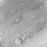
You see, I have an old two-CD-ROM program called "Voyage to the Outer Planets" that includes "Voyager's Greatest Hits," a sample of original IMG files from the Grand Tour. They're the original 800 x 800 complete with reseau marks, and the vignetting is AWFUL. All the images get lighter, not darker, as you get near the edge. It makes homemade stitching look terrible. (Apparently you're supposed to correct them against something called "flatfield" images, but there's nothing like that on the CD. How do you do that?)
I tried the old version on a borrowed XP machine with some Jupiter pictures. It seemed to work OK, except for the extreme corners. Would I really need a corrected version for Voyager images? Or should all the images be temporarily made into negatives, so the edges do go darker instead of lighter?
Thanks.
Posted by: MichaelT Jul 3 2006, 06:03 PM
[...]
I tried the old version on a borrowed XP machine with some Jupiter pictures. It seemed to work OK, except for the extreme corners. Would I really need a corrected version for Voyager images? Or should all the images be temporarily made into negatives, so the edges do go darker instead of lighter?
Thanks.
Well, first I wrote the program specifically for MER images. So, the vignetting that the program is designed to remove is that of the MER cameras, which have vignetting very close to r^2. So you can use it for all images that have vignetting of that kind.
I know the "extreme corner problem", too, which I encountered with images that I had taken with a digital camera. It results from vignetting of higher orders I suppose. So, unfortunately, I suspect, the anti-vignetting program will not be able to eliminate it. Can you post one of the images here so that I can have a go?
Michael
Posted by: edstrick Jul 4 2006, 09:51 AM
The Voyager (mariners, viking) cameras have other problems beside vignetting that sort-of look like vignetting. The detectors were vidicon TUBES... cyindrical electron tubes with a window at one end and a photocathode light-sensative target just behind the window. In general, image quality was good in the central portions of the target and various artifacts increased toward the edges .... the edges of the CIRCULAR target. The corners of the view were closest to those edges.
I suspect that the artifacts are a combination of manufacturing irregularities of the target increasing toward the outer edge and imperfections in the readout electron beam scanning, focussing, intensity, and other quality measures near the edge of the scannable area. At any rate, there is more artifact structure and contrast in the dark exposure images and the flatfield bright exposure images in the corners of these vidicon images than in the central portions. These can include reverse-vignetting-like corner brightening and whatever.
Posted by: jrdahlman Jul 5 2006, 04:47 PM
Sorry for the delay. My website requires me to upload files one at a time.
(Warning: lots of links follow.)
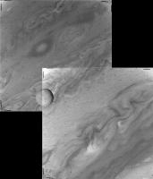
I was trying to hand-stitch two Voyager Jupiter images: C1631753 and C1631755. Here's what it looks like if you just use the uncorrected images:
|
Ugly.
Here are the two of them from my "Voyager's Greatest Hits" CD-ROM, in various versions:
C1631753:
http://home.comcast.net/~jrdahlman/C1631753.imq
http://home.comcast.net/~jrdahlman/C1631753.png
http://home.comcast.net/~jrdahlman/C1631753.jpg
C1631755:
http://home.comcast.net/~jrdahlman/C1631755.imq
http://home.comcast.net/~jrdahlman/C1631755.png
http://home.comcast.net/~jrdahlman/C1631755.jpg
I fed the jpgs into your original anti-vignetting program, and it came up with this:
http://home.comcast.net/~jrdahlman/C1631753_AV.jpg
http://home.comcast.net/~jrdahlman/C1631755_AV.jpg
Not understanding the controls, I also tried them with "pixel protect" set to 0%, whatever that does:
http://home.comcast.net/~jrdahlman/c1631753_av0pct.jpg
http://home.comcast.net/~jrdahlman/c1631755_av0pct.jpg
If you want to see Voyager's vignetting on a blank image, the closest I have is C2683716. (It's actually a look at the moon 1985u1, so there's a dim disc near the middle you can ignore.)
C2683716:
http://home.comcast.net/~jrdahlman/C2683716.imq
http://home.comcast.net/~jrdahlman/C2683716.png
http://home.comcast.net/~jrdahlman/C2683716.jpg
The program didn't know what to do with it:
http://home.comcast.net/~jrdahlman/C2683716_AV.jpg
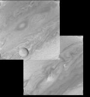
Anyway, a mosiac is improved but not perfect:
|
(Darn it, I can line up the moon or the clouds but not both. Voyager couldn't have moved that fast in 2 minutes! Maybe one needs to be tilted.
http://home.comcast.net/~jrdahlman/voy755753clouds.jpg
Wish I had an auto-stitch program that would run on my machines.)
Posted by: MichaelT Jul 6 2006, 12:37 PM
(Warning: lots of links follow.)
Thanks for the images! I will have a look at them tonight (>19 UTC).
Michael
Posted by: ugordan Jul 6 2006, 01:01 PM
Oh, yes, it could have moved that fast! In fact, it's probably not Voyager's perspective that changed that much as much as Europa progressed onward in its orbit + the clouds themselves are racing too, remember Jupiter is the fastest rotating planet. Europa orbits at a few kilometers per second and that's more than enough to change its position drastically in 2 minutes.
Posted by: um3k Jul 6 2006, 01:49 PM
Another problem is that Voyager images exhibit a large amount of geometric distortion. Correcting this would definitely help with your stitching.
Posted by: MichaelT Jul 6 2006, 05:59 PM
I couldn't get it any better either. I think what edstrick wrote pretty much explains why: There are just too many other effects that cause the brightness differences in the images. I'm sorry that I can't help you there.
Btw.: Have you got access to Photoshop? If you use the filter that removes dust and scratches with a radius of 3 and a threshold value of 10, it removes all the dark dots without visible loss of detail (except the moons shadow, probably).
Michael
[attachment=6580:attachment]
|
Posted by: um3k Jul 6 2006, 08:06 PM
jrdahlman, these websites may come in handy for you:
http://members.optusnet.com.au/serpentis/ - For viewing and processing Voyager images
http://pds-rings.seti.org/catalog/vgriss.html - Nearly complete catalog of Voyager images, including calibration images.
Good luck!
Posted by: jrdahlman Jul 6 2006, 08:59 PM
Oh, I know that you can download all the images. I just have my hands full with one CD, focussing on one planet! (That CD's been sitting here for years--I should do something with it.)
I'm really just playing around. I don't expect to find anything "new."
Downloaded yet another program. If it doesn't gasp and die in my little Libretto, I'll try it out.
By the way, HOW is it geometrically distorted? Fisheye-lens curving?
Posted by: um3k Jul 7 2006, 12:57 AM
Vidicon electron beam scanning distortion. Thus, it varies somewhat from image to image, and is not evenly distributed within the image. That's what the black dots (called reseau marks) all over the image are for. The software I linked to does a fairly reasonable job of removing the distortion, and is capable of removing the reseau marks, although not in a very asthetically pleasing sort of way.
Also, the reason I gave you the link to the site with the image files is that you can download dark frame images there, which the software I linked to can use to remove the "anti-vignetting." That's the best way to do it.
As a side note, vidicons are lousy for scientific imaging.
Posted by: edstrick Jul 7 2006, 11:37 AM
Playing with Voyager 1 wide angle images, I found I could make dark-field images that essentially perfectly canceled out dark-exposure structure and shading in images that had the same parameters.
I found to my distinct horror that there are image sets with apparently identical "relevant" parameters (readout rate, etc) that have different dark-exposure structure and needed separate calibration files.
Playing with Titan Voyager 1 Wide angle frames, I found that on a distinctly overexposed Titan image (exposed for limb or terminator structure), as you approached the moon's disk, there were image displacement fringes on the reseau marks (black dots) as the electrical charge loss in the area of the overexposed moon's image DEFLECTED the image readout electron beam during image readout!
Decalibrating vidicon images is a Siphysus-level task.
Posted by: jrdahlman Jul 10 2006, 06:19 AM
I would like to point out that the program um3k's first link above:
http://pds-rings.seti.org/catalog/vgriss.html
is the program for getting rid of reseau and for correcting the geometric distortion. I've played with it a few days and it works fine even in my little Libretto computer. It has special settings for Voyager or Viking orbiter images, and seems to have almost as many complicated controls as Photoshop! (I imagine.)
The only thing is that it doesn't automatically do the flat-fielding--special flat-field images must be loaded into it. But is has separate settings for "flat-field" and "dark current"--didn't even know there was a difference.
Posted by: edstrick Jul 10 2006, 09:42 AM
Dark current images are those taken with zero exposure. They actually are of two types.. Ones taken with zero exposure, and ones taken with time exposure of a zero-brightness scene, then read out at slower than the maximum possible speed. As a camera's detector "sits" before readout, it accumulates (or a vidicon looses) charge, and the blank image changes with exposure time and readout settings.
A flat-field image is one taken of a uniformly illuminated scene, to calibrate for camera and lens response variations AFTER a perfectly matched dark image is subtracted. You then divide data images by the flat-field to get hopefully clean decalibrated images.
Powered by Invision Power Board (http://www.invisionboard.com)
© Invision Power Services (http://www.invisionpower.com)