Beginner level projection |

  |
Beginner level projection |
 Nov 26 2019, 10:33 AM Nov 26 2019, 10:33 AM
Post
#31
|
|
|
Member  Group: Members Posts: 406 Joined: 18-September 17 Member No.: 8250 |
QUOTE (adamg @ Nov 25 2019, 01:43 PM)  Anyone have any good advice on scaling the RGB to give the closest to true color? I tried these two [0.487, 0.408, 0.172] [0.444, 0.341, 0.155] from Brian's flow and I get a strong orange hue. My colorBalance values specify the upper end of the range of the input components, so you'd divide by them. When rescaled, they are similar to Bjorn's. 1/colorBalance/Min[1/colorBalance] = {1., 1.193, 2.8378} |
 |
 
|
|
Nov 26 2019, 10:54 AM
Post
#32
|
|
|
Member Group: Members Posts: 406 Joined: 18-September 17 Member No.: 8250 |
QUOTE (Bjorn Jonsson @ Nov 25 2019, 03:01 PM) I usually multiply by [1, 1.12, 2.3] after decompanding. I'm surprised that [1, 1, 0.95] seemed close - are you decompanding the images before applying these? I've been wondering, is your natural color process more involved than a scaling? And also how you derived your color balance values? My current (too blue) values come from the median of my flat fields. Early on they came from the max values from an image of Europa. |
|
|
|
|
Nov 26 2019, 12:26 PM
Post
#33
|
|
|
Junior Member Group: Members Posts: 31 Joined: 31-October 19 Member No.: 8699 |
Sounds like I'm miles off for some reason. I used the RDR product assuming it had already been decompanded, I recall I have a range to 4kish so it has certainly been through something.
|
|
|
|
|
Nov 26 2019, 02:48 PM
Post
#34
|
|
 Senior Member Group: Members Posts: 4246 Joined: 17-January 05 Member No.: 152 |
QUOTE (Brian Swift @ Nov 26 2019, 11:54 AM) I've been wondering, is your natural color process more involved than a scaling? And also how you derived your color balance values? In particular, shouldn't a colour space matrix transformation to, eg, sRGB be performed from the raw colour channels? That generally can't be approximated by a simple scaling of each channel. |
|
|
|
|
Nov 26 2019, 06:14 PM
Post
#35
|
|
|
Junior Member Group: Members Posts: 31 Joined: 31-October 19 Member No.: 8699 |
The RDR data set says "For planetary targets, these values are then scaled such that a white surface at the solar distance at the time of imaging and with the commanded exposure time would have a pixel value of 10,000 data numbers.", so I'm assuming the blue already got scaled before I got to it. I probably ought to use the EDR data set if I want to actually know how it got scaled.
Regarding sRGB, it seems sensible to me that you can scale the linear raw IMG which is what I'm doing but should I be trasforming to sRGB at some point? |
|
|
|
|
Nov 26 2019, 09:44 PM
Post
#36
|
|
|
Senior Member Group: Members Posts: 2511 Joined: 13-September 05 Member No.: 497 |
QUOTE (adamg @ Nov 26 2019, 10:14 AM) The RDR data set says "For planetary targets, these values are then scaled such that a white surface at the solar distance at the time of imaging and with the commanded exposure time would have a pixel value of 10,000 data numbers." Well, I wrote that, and I don't know how to make it any clearer than that. "Natural color" requires you to model the human eye response. The Junocam RGB filters are not much like the human eye response (unlike the Bayer pattern used for MSL) so one would have to do something, but I'm not sure what. In case you care, the EDR-RDR scaling code (after decompanding) is CODE ref = [111, 4766, 10331, 12669] # ch4, blue, green, red scale = 16.3 sunrange /= 1.5e8 # km to AU ex = float(i.info["exposure"])*int(i.info["tdi"]) dnout = int(dn*scale/ex/(ref[f]*(5.2)**2/sunrange**2)*10000) -------------------- Disclaimer: This post is based on public information only. Any opinions are my own.
|
|
|
|
|
Nov 27 2019, 04:47 AM
Post
#37
|
|
|
Member Group: Members Posts: 406 Joined: 18-September 17 Member No.: 8250 |
QUOTE (adamg @ Nov 26 2019, 10:14 AM) Regarding sRGB, it seems sensible to me that you can scale the linear raw IMG which is what I'm doing but should I be trasforming to sRGB at some point? My colorBalance scaling is applied to decompanded raw non-calibrated image values. I usually use the "raw" files from the missionjuno.swri.edu, but have also used PDS EDR files. I haven't worked with the RDR files. I don't apply a linear to sRGB conversion unless I want to produce a natural-ish contrast image. Not performing the linear to sRGB makes the files from my pipeline display with more contrast. |
|
|
|
|
Nov 27 2019, 11:30 AM
Post
#38
|
|
|
Junior Member Group: Members Posts: 31 Joined: 31-October 19 Member No.: 8699 |
Interesting, [1,1.23,2.66] I actually dropped my 0.95 so I think you nailed it.
mcaplinger, sorry I didn't spot your name on the technical report, that was pretty lazy of me! Congratulations on such a successful piece of hardware, as an electronics guy it's the camera itself that's got me interested, I've been very impressed. |
|
|
|
|
Nov 27 2019, 06:59 PM
Post
#39
|
|
|
Member Group: Members Posts: 406 Joined: 18-September 17 Member No.: 8250 |
QUOTE (adamg @ Nov 27 2019, 03:30 AM) ...as an electronics guy it's the camera itself that's got me interested, I've been very impressed. Mike will correct me if I'm wrong, but I believe this is the hardware info for the CCD https://www.onsemi.com/pub/Collateral/KAI-2020-D.PDF This and various other JunoCam reference links are at the top of the Juno24u notebook on GitHub. |
|
|
|
|
Dec 9 2019, 02:25 AM
Post
#40
|
|||
|
Junior Member Group: Members Posts: 31 Joined: 31-October 19 Member No.: 8699 |
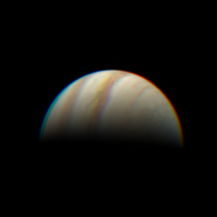
How are peoples' inter frame delays looking?
In the attached images for JNCE_2016239_01C06109_V01 I added the recommended 1ms inter frame delay (right) and also tried 10ms (left) that got it looking better but not perfect. It's probably not right adding this accumulating delay and seems more likely to be some offset between the three colours instead which is why I ask. I did see jitter mentioned but I tried a couple of images and the error seems similar between them so it does seem systematic.
Attached thumbnail(s)
|
||
|
|
|
||
|
Dec 9 2019, 05:50 PM
Post
#41
|
|
|
Senior Member Group: Members Posts: 2511 Joined: 13-September 05 Member No.: 497 |
QUOTE (adamg @ Dec 8 2019, 06:25 PM) How are peoples' inter frame delays looking? If we had ever seen anything that would make the interframe delay different than the header value plus 1 msec, we would have said that, but we haven't. AFAIK nobody has ever said anything about jitter on the interframe delay, only on the start time. I don't have any measurements for the specific image you posted, but for PJ1-6160 the time offset was about 1 pixel different from the reported values. But again, that's a start time offset, not an interframe delay change. -------------------- Disclaimer: This post is based on public information only. Any opinions are my own.
|
|
|
|
|
Dec 9 2019, 06:15 PM
Post
#42
|
|
|
Member Group: Members Posts: 406 Joined: 18-September 17 Member No.: 8250 |
QUOTE (adamg @ Dec 8 2019, 06:25 PM) How are peoples' inter frame delays looking? I add 0.001035 sec to the INTERFRAME_DELAY value. (This is the value ifdAdjustment in selectedCameraParams in my pipeline.) The extra 35us beyond the recommended 1ms is probably only relevant to align features that appear in first and last frames of a 360° image. (BTW, the earth flyby image JNCE_2013282_00C00102_V01.IMG is a good exercise of pipeline robustness) QUOTE In the attached images for JNCE_2016239_01C06109_V01 I added the recommended 1ms inter frame delay and also tried 10ms that got it looking better but not perfect. It's probably not right adding this accumulating delay and seems more likely to be some offset between the three colours instead which is why I ask. I did see jitter mentioned but I tried a couple of images and the error seems similar between them so it does seem systematic. The ~20ms jitter mentioned in juno_junocam_v03.ti just applies to the START_TIME. Several pipelines perform some type of limb fit to produce a refined start time estimate. |
|
|
|
|
Dec 9 2019, 06:29 PM
Post
#43
|
|
 IMG to PNG GOD Group: Moderator Posts: 2250 Joined: 19-February 04 From: Near fire and ice Member No.: 38 |
The value you add to the interframe delay should always be 1 ms (or close to 1 ms) as Mike said. If you need something like 10 ms there is a bug somewhere in your code. Small deviations from 1 ms are possible due to various factors (limb position uncertainties in especially the hi-res images, possible variations in the haze or cloudtop altitude, tiny variations in Juno's spin rate etc.). I have never gotten values lower than 0.5 ms or higher than 1.5 ms (and I should add that if I get 0.5 or 1.5 that's a big deviation - I usually consider values like these with some suspicion).
I usually determine the start time, end time and interframe delay by measuring the position of Jupiter's limb in the first and last framelets where a significant part of Jupiter's limb is visible. These measurements are then used to automatically determine the actual image time of these two framelets, the interframe delay and from this the start time. If everything is working correctly the color channel alignment of the resulting image should be close to perfect - maybe a small error (1 pixel or 2 at most) near the image edges in a few cases. |
|
|
|
|
Dec 10 2019, 11:20 PM
Post
#44
|
|
|
Junior Member Group: Members Posts: 31 Joined: 31-October 19 Member No.: 8699 |
Thanks guys, apparently I'm a goose. I hard coded the inter frame delay from that P8 image I was looking at before (my code is only a couple hundred lines long so it's a bit bare bones) and this one is different by 8ms.
|
|
|
|
|
Aug 3 2020, 02:01 PM
Post
#45
|
|
|
Newbie Group: Members Posts: 15 Joined: 1-August 20 Member No.: 8847 |
Hello All,
I wasn't sure if I should post here or make a new topic. I'm happy to do that if it fits better with this forum. I see a discrepancy in what fovtrg_c tells me vs what I get from sincpt_c. I'm sure I'm doing something wrong but I've been hacking around for a week or so (nights and weekends project  and I've not made much progress. So, I figured I'd ask the experts. and I've not made much progress. So, I figured I'd ask the experts.My goal here is to understand the data, eventually I want to turn my code into an image processing pipeline. When I powered through and got to a 3d image it looks OK, but is very blurry. The color does not align well etc. So I decided to step back to the beginning and try to ensure everything is doing what I expect. That's when I ran across this image that has Io in it. Using that as a test vehicle has brought into sharp focus the miss that's happening in my code. So I figured it would make a great subject to get my code straightened out before moving back to my 3d image creation. I've listed my code below with some of the results in the comments. Any pointers to what I'm doing wrong would be most welcome. Thanks! I load and parse these files. JNCE_2019307_23C00028_V01.LBL JNCE_2019307_23C00028_V01.IMG furnsh_c("JNO_SCLKSCET.00102.tsc") furnsh_c("juno_junocam_v03.ti") furnsh_c("juno_struct_v04.bsp") furnsh_c("juno_v12.tf") furnsh_c("naif0012.tls") furnsh_c("pck00010.tpc") furnsh_c("trimmed_jup310.bsp") furnsh_c("juno_sc_rec_191102_191104_v01.bc") furnsh_c("spk_rec_191010_191201_191210.bsp") // startTime (from LBL) - 2019-11-03T22:26:16.510 // frame 29 // from the juno_junocam_v03.ti kernel // INS-61500_START_TIME_BIAS = 0.06188 // INS-61500_INTERFRAME_DELTA = 0.001 // from the LBL file // INTERFRAME_DELAY = 0.371 <s> // 2019-11-03T22:26:16.510 + INS-61500_START_TIME_BIAS + (0.371 + 0.001) * frameNumber // so frame time is: // 2019-11-03T22:26:27.35988 str2et_c("2019 Nov 03 22:26:27.360", &frameTime) str2et_c returned 6.26092e+08 fovtrg_c("JUNO_JUNOCAM_RED", "IO", "ELLIPSOID", "IAU_IO", "LT+S", "JUNO", 6.26092e+08) fovtrg_c returned true // Examaning the image from the red part of frame 29 I see Io is present on // pixel 154, 124 // and several others, but that one is kind of in the 'center' of the visible Io // I'm happy to upload the image I'm referring to. My code takes the IMG data from the PSD file (mentioned above) and turns that into a PNG file. // I tried two approaches to finding the pointing vector, // bilinear interpolate over the pointing vectors in the kernel // INS-61503_FOV_BOUNDARY_CORNERS = ( // -0.47949606, 0.09218676, 0.87268845 // -0.47518685, 0.16768048, 0.86375964 // 0.48724863, 0.16654879, 0.85723408 // 0.49166330, 0.09156385, 0.86595800 // ) // u 0.081468 ((154 - 23) / 1608) // v 0.96875 (124 / 128) bilinearInterpolate(0.081468, 0.96875, [ {-0.479496, 0.0921868, 0.872688} {-0.475187, 0.16768, 0.86376} {0.487249, 0.166549, 0.857234} {0.491663, 0.0915639, 0.865958} ] pointing = {-0.396892, 0.16523, 0.863507} sincpt_c("Ellipsoid", "IO", 6.26092e+08, "IAU_IO", "CN+S", "JUNO", "JUNO_JUNOCAM", {-0.39689193, 0.1652304, 0.86350652}) sincpt_c returned false // I also implemented the distord/undistort camera model // pixel = {154, 124} // pointing = {-0.398252, 0.166199, 0.902094} sincpt_c("Ellipsoid", "IO", 6.26092e+08, "IAU_IO", "CN+S", "JUNO", "JUNO_JUNOCAM", {-0.39825207, 0.16619926, 0.90209373}) sincpt_c returned false // I also spent some time adding an arbitrary time offset (up to 0.1 seconds, by a 0.025 increment) // and I do end up with intersections but they are several pixels to the left of the captured image. |
|
|
|
|

|
Lo-Fi Version | Time is now: 25th April 2024 - 10:05 PM |
|
RULES AND GUIDELINES Please read the Forum Rules and Guidelines before posting. IMAGE COPYRIGHT |
OPINIONS AND MODERATION Opinions expressed on UnmannedSpaceflight.com are those of the individual posters and do not necessarily reflect the opinions of UnmannedSpaceflight.com or The Planetary Society. The all-volunteer UnmannedSpaceflight.com moderation team is wholly independent of The Planetary Society. The Planetary Society has no influence over decisions made by the UnmannedSpaceflight.com moderators. |
SUPPORT THE FORUM Unmannedspaceflight.com is funded by the Planetary Society. Please consider supporting our work and many other projects by donating to the Society or becoming a member. |
|