Vignetting, discussion about methods of resolution |

  |
Vignetting, discussion about methods of resolution |
 Nov 11 2005, 04:09 PM Nov 11 2005, 04:09 PM
Post
#31
|
|
 Senior Member  Group: Moderator Posts: 3431 Joined: 11-August 04 From: USA Member No.: 98 |
QUOTE (dilo @ Sep 14 2005, 06:38 PM) WOW! MichaelT, I think would be really GREAT to implement your algorithm inside MMB... I would know opinion from the other Michael on this item...   If there were a Java version of this algorithm, it might be possible to put it into MMB. It would be neat to have Navcam mmbpans with anti-vignetted images. Since MMB is open-source now somebody else could work on this as well. |
 |
 
|
|
Nov 13 2005, 08:02 AM
Post
#32
|
||
 Senior Member Group: Members Posts: 2492 Joined: 15-January 05 From: center Italy Member No.: 150 |
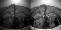
QUOTE (mhoward @ Nov 11 2005, 04:09 PM) If there were a Java version of this algorithm, it might be possible to put it into MMB. It would be neat to have Navcam mmbpans with anti-vignetted images. Since MMB is open-source now somebody else could work on this as well. This is a very important item, I already suggested to implement anti-vignetting in MMB some time ago! I do not know Opens Source / Java, hope some expert volunteer will work on this. Apart the advantage for perfect stitching, not only NavCam will improve. Biggest single-image benefits would be on hazcam, as showed in the following example from Sol639 Opportunity (I made also some image processing in addition to anti-vignetting, now I wonder how much information can be recovered from extreme-conditions images like this!)
Attached thumbnail(s)
-------------------- I always think before posting! - Marco -
|
|
|
|
|
|
|
Nov 13 2005, 06:17 PM
Post
#33
|
|
|
Member Group: Members Posts: 156 Joined: 18-March 05 From: Germany Member No.: 211 |
Hi Michael,
it would indeed be very nice if someone implemented it into MMB. Unfortunately, that won't be me as I do not have experience in Java-programming. I will post the code of my anti-vignetting routine in the next couple of days. So I hope that someone else can transform the code into Java. Michael |
|
|
|
|
Nov 13 2005, 06:49 PM
Post
#34
|
|
 Member Group: Members Posts: 257 Joined: 18-December 04 Member No.: 123 |
I would be interested in giving it a go. I made a java attempt at MichaelT's
DD enhancing algorithm before so I fancy a go at this even of some else beats me to it  But I think I might need a bit of expansion on parts of the algorithm posted at the start of the thread. I'm not entirely sure of the different colour spaces. For example can you convert directly from greyscale to LAB or must it be in RGB. I have been looking and have found conversion from RGB to XYZ to LAB but not directly from RGB to LAB. >>0. convert the image to LAB color space to handle color and luminance independently And then >>6. so,as a last step I create a b-spline (or linear) interpolated version of the correction curve. In terms of getting the curve and things I'm a bit  I'll wait for MichaelT to post his routine I think, but I'll give it a go. -------------------- Turn the middle side topwise....TOPWISE!!
|
|
|
|
|
Nov 14 2005, 06:12 PM
Post
#35
|
|
|
Member Group: Members Posts: 156 Joined: 18-March 05 From: Germany Member No.: 211 |
QUOTE (jaredGalen @ Nov 13 2005, 06:49 PM) I would be interested in giving it a go. I made a java attempt at MichaelT's DD enhancing algorithm before so I fancy a go at this even of some else beats me to it But I think I might need a bit of expansion on parts of the algorithm posted at the start of the thread. I'm not entirely sure of the different colour spaces. For example can you convert directly from greyscale to LAB or must it be in RGB. I have been looking and have found conversion from RGB to XYZ to LAB but not directly from RGB to LAB. >>0. convert the image to LAB color space to handle color and luminance independently And then >>6. so,as a last step I create a b-spline (or linear) interpolated version of the correction curve. In terms of getting the curve and things I'm a bit I'll wait for MichaelT to post his routine I think, but I'll give it a go. Ok, its great that you want to try it  I hope you find the following lines useful. By now I completely skipped using FFT . It can just as well be done without. I hope you find the following lines useful. By now I completely skipped using FFT . It can just as well be done without.Concerning LAB etc: I don't know how to convert between the different color spaces. I found that the amount of vignetting in the color images is different between the RGB channels. So I don't know what it would be like if you applied the anti-vignetting to the two color-channels of LAB. Probably that gives some strange results? Don't know. The other questions are hopefully answered below: These lines of code are to generate the template function (see below). First a vector T is generated that is XDIM long (XDIM: the x-dimension of the image) and runs from -pi/2 to +pi/2. The FINDGEN command outputs a vector of length XDIM containing values in ascending order from 0 to XDIM - 1. EM = COS(T) * 0.1 + 0.9 is used as basis for the template matrix. As you can see it has a cosine shape. As initial value of the vignetting I assume 10%, ie. the factor 0.1. The 0.9 is added so that the maximum value is 1.0 while the minimum is 10% lower. This vector is filled in a matrix of size (XDIM, XDIM) if XDIM > YDIM otherwise YDIM is used (IF statement). To obtain a rotation-symmetric matrix, the transpose is added to that matrix and everything devided by two (ES). To match the size of the image, the unneccessary data are removed (ESS). To save time, the template is later fitted to a size-reduced image, and, therefore, reduced to the given size using the CONGRID-command. The size then is (512, YDIM*512/XDIM) or (XDIM*512/YDIM, 512) depending on the image (landscape or portrait). [code begins] IF XDIM GE YDIM THEN BEGIN DISX = 512.0 DISY = YDIM * 512.0 / XDIM T = (FINDGEN(XDIM) * 1.0 * !PI / XDIM -!PI / 2.0) EM = COS(T) * 0.1 + 0.9 ES1 = {ES11: EM} ES1 = REPLICATE(ES1, XDIM) ES = (ES1.ES11 + TRANSPOSE(ES1.ES11)) / 2.0 ESS = ES[*, DIFF: DIFF + YDIM - 1] ESS2 = CONGRID(ES[*, DIFF: DIFF + YDIM - 1], DISX, DISY) ENDIF ELSE BEGIN DISX = XDIM * 512.0 / YDIM DISY = 512.0 T = (FINDGEN(YDIM) * 1.0 * !PI / YDIM -!PI / 2.0) EM = COS(T) * 0.1 + 0.9 ES1 = {ES11: EM} ES1 = REPLICATE(ES1, YDIM) ES = (ES1.ES11 + TRANSPOSE(ES1.ES11)) / 2.0 ESS = ES[DIFF: DIFF + XDIM - 1, *] ESS2 = CONGRID(ES[DIFF: DIFF + XDIM - 1, *], DISX, DISY) ENDELSE [code ends] No comes the routine to fit the template to the image. It is rather complicated... Using an iterative process I try to get as close as possible to the optimal fit. There are likely quicker/better ways to do this. Firstly, ESS2, the template (see above) is now called E. The aim is to determin a parameter NR so that E^NR optimally fits the image. First I calculate E^NR for three preset values given in INTR, yielding ESSR. Then I divde the image ( B ) by ESSR, which results in a temporary vignetting reduced image (FP_TEMP_R). In step two I run through all rows (chosen by the user, actually rows between APY1 and APY2. That allows to do the fitting for parts of the image, eg. the sky, only) of FP_TEMP_R and fit a 2nd-order polynomial to the pixel-values (X is there to provide some x-values for the fit). The parameters of which are stored in RR. If an image is completely without vignetting, I assume that the sum PTR of the squared 2nd-order parameters (RR[2]) is minimal, as the "curvature" of the pixel values caused by the vignetting should be gone. You might ask now, why I fit a 2nd-order polynomial to the supposed cosine shaped vignetting. Well, I found that the difference is not that large in most cases and that there are ready-to-use IDL routines for the polynomial fit. As you can see I do this for the three values given in INTR [I1, I2, I3],. After doing so, I look for which of the two values PTR is minimal. I then use these two values from INTR (would be either [I1, I2] or [I2, I3])to define a new INTR with three new values. Two of which are I1 and I2 or I2 and I3 and a value in between the two (actually not quite I1, I2 or I2, I3 as the optimal value might still be in the respective other interval, but close to I2). The whole process then starts again with these new values. That is done a total of 15 times. After that the interval INTR has converged sufficiently close to the optimal value of NR. [code begins] E = ESS2 INTR = [0.0D, 15.0D, 30.0D] X = DINDGEN(DISX) - DISX / 2.0D + 0.5D RR = FLTARR(3, DISY) RTR = FLTARR(3) FOR K = 0, 14 DO BEGIN FOR J = 0, 2 DO BEGIN ESSR = E^INTR[J] FP_TEMP_R = B / ESSR FOR I = APY1, APY2 - 1, 1 DO BEGIN WAIT, 0.00001 RR[*, I] = POLY_FIT(X, FP_TEMP_R[*, I], 2) ENDFOR RTR[J] = TOTAL(SQRT(RR[2, *]^2)) ENDFOR SRTR = SORT(ABS(RTR)) INTR = [INTR[SRTR[0]], (INTR[SRTR[0]]+INTR[SRTR[1]]) / 2.0D, INTR[SRTR[1]]] INTR = INTR[SORT(INTR)] INTR = [INTR[0] - 0.05D * (INTR[1] - INTR[0]), INTR[1], INTR[2] + 0.05D * (INTR[2] - INTR[1])] ENDFOR [code ends] All that can be done for all three color channels, as the amount of vignetting can be different for red, green and blue. Not for gray-scale images, though. The code below shows what would be done for a gray-scale jpeg after NR (actually the parameter for the red-channel) has been determined: [code begins] NR = INTR[SRTR[0]] NG = NR NB = NR ESST = ESS^NR CR = CRS / ESST CG = CGS / ESST CB = CBS / ESST [code ends] Where CRS, CGS and CBS are the original color channels of the image. The new ones are CR, CG and CB. In my program you can additionally choose howstrong the anti-vignetting is applied, so the final result would by something like: CR = AV * CRS / ESST + (1 - AV) * CRS etc., with AV between 0 and 1 (actually AV< 1 would be/is possible). But I think this part is the most interesting for you jaredGalen. Most important is, I think, that the determination of the amount of vignetting can be done with a size reduced image. The found parameter can then be used for the original image. That saves a lot of time The complete program can be found here Unfortunately, I did not have time to comment it very much. I know, this is bad  Any other questions Michael |
|
|
|
|
Nov 14 2005, 06:33 PM
Post
#36
|
|
|
Member Group: Members Posts: 257 Joined: 18-December 04 Member No.: 123 |
Wow, okay.
Looks like I have my work cut out for me. Cripes, I'll have to pour over what you have said and your code first before I go asking more questions. The color space issue is concerning me a little but I'll leave that til I have a metter understanding of what you do. I have a feeling I will have plenty of questions. If anyone else outhere is thinking of doing this then by all means drop in. Edit: Just realised the algorithm I was looking at originally wasn't posted by Michael. Muppetesque moment for me  . That clears a few things up. Sorry about that. . That clears a few things up. Sorry about that.Don't worry. I have everything under control
-------------------- Turn the middle side topwise....TOPWISE!!
|
|
|
|
|
Nov 14 2005, 11:15 PM
Post
#37
|
|
|
Member Group: Admin Posts: 468 Joined: 11-February 04 From: USA Member No.: 21 |
Michael, thank you for sharing the code to this application. I've found the program very useful, and look forward to digging into its inner workings a bit deeper.
Jared, since vignetting is a camera effect, I'm pretty sure it would be inappropriate to use this application in Lab space. The L channel is shaped similar to a cube root function as it is intended to be a perceptive measure of brightness, and is therefore not linear with photon count like the raw images (well, in a perfect world at least . This means the 'fit' used to determine the amount of vignetting would be even more complicated if you used L instead of the actual pixel brightness through a given filter. The ab parameters concern themselves only with the ratio between color channels (or in MERs case, the raw images) and the only way to know if you have accurately described those would be to use this on the raw images before determining the color at each pixel.
|
|
|
|
|
Nov 15 2005, 02:50 AM
Post
#38
|
|
 Senior Member Group: Moderator Posts: 2262 Joined: 9-February 04 From: Melbourne - Oz Member No.: 16 |
How long does this program take to run for you guys?
I got it running on my Mac yesterday but it takes 4 - 5 mins on each raw pancam frame! I know it is a complicated procedure and it's running through a virtual machine so it's not going to be instantaneous but my activity monitor says it's only using about 10% of my CPU. Just wondering... James -------------------- |
|
|
|
|
Nov 15 2005, 09:05 AM
Post
#39
|
|
|
Member Group: Members Posts: 257 Joined: 18-December 04 Member No.: 123 |
QUOTE (slinted @ Nov 15 2005, 12:15 AM) Jared, since vignetting is a camera effect, I'm pretty sure it would be inappropriate to use this application in Lab space. Thanks for the advice, the Lab color space thing got into my head from an earlier post in this thread that I though was connected to the current version of michaels app. I realise now I can totally ignore it. Thankfully, didn't like where it lead me I will have few questions, have to wait till tonight though. -------------------- Turn the middle side topwise....TOPWISE!!
|
|
|
|
|
Nov 15 2005, 10:04 AM
Post
#40
|
|
|
Member Group: Members Posts: 156 Joined: 18-March 05 From: Germany Member No.: 211 |
QUOTE (jamescanvin @ Nov 15 2005, 02:50 AM) How long does this program take to run for you guys? I got it running on my Mac yesterday but it takes 4 - 5 mins on each raw pancam frame! I know it is a complicated procedure and it's running through a virtual machine so it's not going to be instantaneous but my activity monitor says it's only using about 10% of my CPU. Just wondering... James Thats really a long time  I have a 2.8 GHz Windows PC (512 MB ram) and it usually takes about 5 seconds to process one image, using the virtual machine... What about the other users? How long does it take you to get one image done? Michael |
|
|
|
|
Nov 15 2005, 10:51 AM
Post
#41
|
|
|
Member Group: Members Posts: 877 Joined: 7-March 05 From: Switzerland Member No.: 186 |
The same to me - 5 seconds.
My PC system runs 2,4 GHz Pentium© 4 That's most probably not a rate of calculation problem. -------------------- |
|
|
|
|
Nov 15 2005, 01:34 PM
Post
#42
|
|
|
Senior Member Group: Moderator Posts: 2262 Joined: 9-February 04 From: Melbourne - Oz Member No.: 16 |
Hmm, 5 seconds eh, that's a bit quicker than 5 mins!
Anybody else got this working on a Mac? -------------------- |
|
|
|
|
Nov 15 2005, 05:28 PM
Post
#43
|
|
 Chief Assistant Group: Admin Posts: 1409 Joined: 5-January 05 From: Ierapetra, Greece Member No.: 136 |
no mac, but 3 seconds, although it might well be a bit slower in a batch.
so yes, 5 mins is Hope you figure it out. Nico -------------------- photographer, space imagery enthusiast, proud father and partner, and geek.
http://500px.com/sacred-photons & |
|
|
|
|
Nov 15 2005, 11:13 PM
Post
#44
|
|
|
Senior Member Group: Moderator Posts: 2262 Joined: 9-February 04 From: Melbourne - Oz Member No.: 16 |
QUOTE (NIX @ Nov 16 2005, 04:28 AM) Hope you figure it out. I hope so too! At least it works though. And I can always just leave it running in the background all day on batch mode. Alternately I can always run multiple versions to get it using a bit more of my CPU (further to saying it was using 10% before, I watched it in Activity monitor and most of the time it's at no more than 3%!) My Mac is technically owned by the university who have an IDL site licence so I might just get the real thing installed and try that. Or just run it at work on Linux. Lots of options it's sure not going to stop me making pans, I've only just got the hang of it! James -------------------- |
|
|
|
|
Nov 16 2005, 08:47 AM
Post
#45
|
|
|
Member Group: Members Posts: 156 Joined: 18-March 05 From: Germany Member No.: 211 |
I made a minor modification to the program. I don't know whether that will make any difference to the problem that you encountered James. Just try it out and tell me what the result is. Version 2.0.1 can be found here: AntiVig
Michael |
|
|
|
|

|
Lo-Fi Version | Time is now: 18th April 2024 - 06:57 PM |
|
RULES AND GUIDELINES Please read the Forum Rules and Guidelines before posting. IMAGE COPYRIGHT |
OPINIONS AND MODERATION Opinions expressed on UnmannedSpaceflight.com are those of the individual posters and do not necessarily reflect the opinions of UnmannedSpaceflight.com or The Planetary Society. The all-volunteer UnmannedSpaceflight.com moderation team is wholly independent of The Planetary Society. The Planetary Society has no influence over decisions made by the UnmannedSpaceflight.com moderators. |
SUPPORT THE FORUM Unmannedspaceflight.com is funded by the Planetary Society. Please consider supporting our work and many other projects by donating to the Society or becoming a member. |
|