Juno development, launch, and cruise, Including Earth flyby imaging Oct 9 2013 |

  |
Juno development, launch, and cruise, Including Earth flyby imaging Oct 9 2013 |
 Aug 26 2015, 01:26 AM Aug 26 2015, 01:26 AM
Post
#541
|
||
|
Senior Member  Group: Members Posts: 2346 Joined: 7-December 12 Member No.: 6780 |
... exchanged red and blue:
Once more I'm surprised about human color perception. Colors look more variable (and very similar to former renderings as a cross-check), although it's the same numerical data. It's probably due to the low sensitivity of the eye to blue. |
|
 |
 
|
|
|
Aug 26 2015, 02:19 AM
Post
#542
|
|
|
Senior Member Group: Members Posts: 2509 Joined: 13-September 05 Member No.: 497 |
That looks good, especially if you white-balance it, but the problem has always been in the overlap region where you need to combine framelets from the top and bottom of the image to get full RGB coverage.
-------------------- Disclaimer: This post is based on public information only. Any opinions are my own.
|
|
|
|
|
Aug 26 2015, 11:06 AM
Post
#543
|
|
|
Senior Member Group: Members Posts: 2346 Joined: 7-December 12 Member No.: 6780 |
Thanks!
I'm aware of the problem with the overlap region. But I think the long-term best approach is, to solve the issues bottom-up. The overlap mismatch is imo mainly a high-level phenomenon induced by the change of perspective. It will need a modeling of the surface properties to do more than just retouch the discontinuities. The other non-negligible effect is from light scattering. Since the latter is more basic, and a more general issue anywhere on and near bright objects, I'm inclined to give the solution of this issue a higher priority. Then, after proper projection, a closer look to the causes of the residual mismatch, I think, appears to be the more promising strategy. For the Juno project I'm favoring the science objectives above "pretty pictures", although the latter may be a result of the first. This means a deterministic and reproducible (at least verifiable) processing of the images, and data reduction in a way that the raw images can be explained / simulated from the reduced data and residuals, where the reduced data should describe physical entities, if possible. The goal is, to make preliminary reduced data available as fast as possible, such that they can be used for the next planning cycle to maximize science return. I don't know by now how close I can get to this goal, but the only way to approch it is to work accurately on each reduction step. For horizontal wind speed measurements we may need geometric subpixel accuracy. Detection of composition-induced color changes due to vertical winds or turbulence needs accurate color calibration. Detection of lightnings requires proper distinction of CRs and scattered light from lightnings. |
|
|
|
|
Aug 27 2015, 12:22 PM
Post
#544
|
|||||
|
Senior Member Group: Members Posts: 2346 Joined: 7-December 12 Member No.: 6780 |
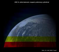
Exchange of the red and blue channel required adjusting assumed filter layout on the camera CCD:
Distorted example subframe:
Assumed optical center for the images of the current post: (824, 466), with (0, 0) the lower left corner. Pinhole FOVs before Brown distortion for 1648 pixels: red 59.90°, green 60.00°, blue 60.00°. Per distorted subframe displacements: (-1.8, 114.0) for the upper (southern) efb12 fragment, (-1.8, 114.5) for the lower (northern) efb12 fragment, (0.0 113.6) for the Moon. Other parameters as in previous version. QUOTE (mcaplinger @ Aug 26 2015, 04:19 AM)  That looks good, especially if you white-balance it, ... ... addressing at least this part: Moon (efb01) in raw colors: 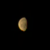 Moon white-balanced with weights 0.510 for red, 0.630 for green, and 1.0 for blue. Weights applied to the square-root encoded raw colors: 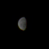 4-fold saturation stretched: 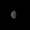 16-fold saturation stretched: 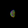 Intention: Using Moon as grey calibration target. Same white-balancing weights applied to efb12 (cropped) with the above parameter adjustments:
|
||||
|
|
|
||||
|
Nov 4 2015, 09:42 PM
Post
#545
|
|
 Member Group: Members Posts: 555 Joined: 27-September 10 Member No.: 5458 |
USTREAM presentation coming up tomorrow night.
The Juno Mission to Jupiter QUOTE Upcoming Event: The Juno Mission to Jupiter Nov. 5, 2015, at 7 p.m. PT (10 p.m. ET, 0300 UTC) Launched in August 2011, the Juno spacecraft will reach Jupiter in July 2016. Jupiter is the largest planet in our solar system, and likely the first to form. Its formation is key to understanding how our solar system began. It has the strongest magnetic field of any known planet, and its magnetosphere is arguably the largest structure in our solar system. Despite Jupiter's importance, and the fact that it was one of the very first astronomical objects to be studied with a telescope, major aspects of the giant planet remain a mystery. We don't yet understand its interior structure, including the size or even existence of a central core. Juno will investigate these and other scientific questions, improving our understanding of the history of our solar system and our own origin story. Speaker: Dr. Steven Levin, Juno Project Scientist -------------------- |
|
|
|
|
Dec 11 2015, 09:33 PM
Post
#546
|
|
 Senior Member Group: Members Posts: 1729 Joined: 3-August 06 From: 43° 35' 53" N 1° 26' 35" E Member No.: 1004 |
an interesting paper (currently in open access) on the other camera on Juno
MicroASC instrument onboard Juno spacecraft utilizing inertially controlled imaging |
|
|
|
|
Dec 18 2015, 03:04 PM
Post
#547
|
|
|
Senior Member Group: Members Posts: 2346 Joined: 7-December 12 Member No.: 6780 |
Phase of selecting and discussing points of interest has started a few days ago.
======= (I'm still working on the analysis of EFB03 straylight. Lots of (tricky) calculations, programming and tests, needs some more time to be ready for a post.) |
|
|
|
|
Jan 8 2016, 09:55 PM
Post
#548
|
|
 Administrator Group: Admin Posts: 5172 Joined: 4-August 05 From: Pasadena, CA, USA, Earth Member No.: 454 |
As we're now just about 6 months from arrival, it's time to create a separate subforum for Juno.
I decided not to close this topic in case anyone else wants to post Earth flyby imaging work; but please continue discussion of the ongoing mission in the Jupiter Approach thread. I also split off Gerald's ongoing discussion of stray light into its own thread. -------------------- My website - My Patreon - @elakdawalla on Twitter - Please support unmannedspaceflight.com by donating here.
|
|
|
|
|
Apr 27 2016, 10:16 AM
Post
#549
|
|||
|
Senior Member Group: Members Posts: 2346 Joined: 7-December 12 Member No.: 6780 |
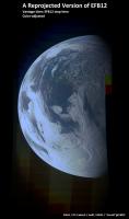
QUOTE (mcaplinger @ Aug 26 2015, 04:19 AM) ... but the problem has always been in the overlap region where you need to combine framelets from the top and bottom of the image to get full RGB coverage. The geometry part appears to be feasible. This is a reprojected version, assuming Earth as a sphere, with a manually defined straight line as trajectory:
(I tried SPICE, but my own code and simplified Earth model appears to be only moderately compatible with my attempt to obtain the according SPICE trajectory; discrepancies of a few kilometers or a few tens of It was necessary to model Earth's rotation. Neglecting the discrepancy of up to 13 km is well visible. Here a crop of the difficult overlap region:
The fully resolved png of the whole globe, supersampled with 60 pixels per (camera) degree, would have been 40MB. After the manual experiments, I'm now confident to know the relevant parameter space for automated geometric optimization; full theoretical treatment and implementation will take one month at least, I think. Adjusting the color between the hemispheres (flatfield, Lambert, Rayleigh, interline smear, stray light, etc.) is on my list, but first I'm curious, whether I can match the CH4 images with the RGB images. |
||
|
|
|
||
|
Apr 27 2016, 10:19 AM
Post
#550
|
||
|
Senior Member Group: Members Posts: 2346 Joined: 7-December 12 Member No.: 6780 |
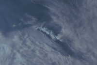
... And here a crop of the fully resolved png, showing an interesting feature near/in Antarctica, just because it's beautiful:
|
|
|
|
|
|
|
Apr 27 2016, 06:15 PM
Post
#551
|
|
|
Senior Member Group: Members Posts: 2509 Joined: 13-September 05 Member No.: 497 |
QUOTE (Gerald @ Apr 27 2016, 02:16 AM) ...with a manually defined straight line as trajectory Could you describe what this looked like? Obviously errors in position could explain the mismatches, but I've always assumed that the reconstructed SPICE trajectory would be extremely accurate in the Earth frame, and this implies that it might not be. -------------------- Disclaimer: This post is based on public information only. Any opinions are my own.
|
|
|
|
|
Apr 28 2016, 11:40 AM
Post
#552
|
|
|
Senior Member Group: Members Posts: 2346 Joined: 7-December 12 Member No.: 6780 |
There are certainly various possible causes for the mismatch. Besides inaccuracies in my software, this might include clock offsets or inaccuracies of the SPICE trajectory interpolation. Your cross-checking may distinguish these effects.
Here some technical data of the above renditions: Actually used trajectory points relative to Earth center, Earth assumed as a sphere with radius 6378.1 km and a rotation period of 86400 seconds, with a second defined by 370 milliseconds per subframe (subframes in reverse chronological order) : Subframe 0: (-2213.74, 2975.31, 8673.86) Subframe 81: (-2566.28, 3052.83, 8826.01) Camera rotation (around x-axis) per subframe: -0.07716 (radians) Scale factor pinhole: 1480.0 Optical center: (814.276331289716; 600.0) K1 = -3.839251e-8 K2 = 0.0 Frame of reference for attitude: efb12, subframe 0. ======================== Related SPICE data Script for spy.exe: CODE SAVE TO spy_results_efb12_v01_EARTH_JUNO_JUNOCAM.txt; LOAD E:\juno\spice\kernels\lsk\naif0011_dos.tls; LOAD E:\juno\spice\kernels\sclk\JNO_SCLKSCET.00038_dos.tsc; LOAD E:\juno\spice\kernels\fk\juno_v08_dos.tf; LOAD E:\juno\spice\kernels\pck\pck00010_dos.tpc; LOAD E:\juno\spice\kernels\ck\juno_sc_nom_110807_171016_v01.bc; LOAD E:\juno\spice\kernels\ck\juno_sc_rec_131006_131012_v01.bc; LOAD E:\juno\spice\kernels\spk\spk_rec_131005_131014_131101.bsp; SET START TIME 2013-10-09T19:12:32.006; SET STOP TIME 2013-10-09T19:13:02.346; SET N 82; SET TIME FORMAT YYYY-MM-DDTHR:MN:SC.###; SET OBSERVER JUNO; SET TARGET EARTH; SET FRAME JUNO_JUNOCAM; SET PAGE WIDTH 255; SET NUMBER FORMAT F18.8; SHOW ALL; SAMPLE POSITION; *_dos.t* are derived from original SPICE files for cr/lf convention. Batch call: CODE \spice\util64\spy.exe -b -start cmd_efb12_v01_EARTH_JUNO_JUNOCAM.spy Relevant output line (corresponding to above subframe 0) : QUOTE 2013-10-09T19:13:02.346 2333.74449340 2595.31213004 8763.96368790 Note the discrepancy to the assumed trajectory position for subframe 0, above. Excerpt of JNCE_2013282_00C102_V01.LBL: QUOTE STOP_TIME = 2013-10-09T19:13:02.346
|
|
|
|
|
Apr 29 2016, 10:36 AM
Post
#553
|
|
|
Junior Member Group: Members Posts: 62 Joined: 11-July 11 Member No.: 6058 |
QUOTE (Gerald @ Apr 27 2016, 11:19 AM) ... And here a crop of the fully resolved png, showing an interesting feature near/in Antarctica, just because it's beautiful: That is South Georgia, a British Overseas Territory a few hundred miles to the east of the Falkland Islands and, by all accounts, an amazing place to visit. The British Antarctic Survey maintain a year-round presence there. |
|
|
|
|
Apr 29 2016, 04:22 PM
Post
#554
|
||
|
Senior Member Group: Members Posts: 2346 Joined: 7-December 12 Member No.: 6780 |
Thanks for identifying the island!
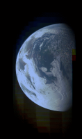
 Here a time-lapsed animation of efb12 along the linearly extrapolated trajectory assumed for rgb registering, in steps of about 3.7 real-time seconds per frame, replayed with 0.05 seconds per frame, using 25 reprojected frames, resolution three pixels per (camera) degree:
|
|
|
|
|
|
|
Apr 29 2016, 04:26 PM
Post
#555
|
|
|
Junior Member Group: Members Posts: 62 Joined: 11-July 11 Member No.: 6058 |
Beautiful, just beautiful. Can't wait to see Jupiter's cloud decks with this cam!
|
|
|
|
|

|
Lo-Fi Version | Time is now: 16th April 2024 - 05:17 PM |
|
RULES AND GUIDELINES Please read the Forum Rules and Guidelines before posting. IMAGE COPYRIGHT |
OPINIONS AND MODERATION Opinions expressed on UnmannedSpaceflight.com are those of the individual posters and do not necessarily reflect the opinions of UnmannedSpaceflight.com or The Planetary Society. The all-volunteer UnmannedSpaceflight.com moderation team is wholly independent of The Planetary Society. The Planetary Society has no influence over decisions made by the UnmannedSpaceflight.com moderators. |
SUPPORT THE FORUM Unmannedspaceflight.com is funded by the Planetary Society. Please consider supporting our work and many other projects by donating to the Society or becoming a member. |
|