Mars 3 (Various Topics Merged) |

  |
Mars 3 (Various Topics Merged) |
 Oct 18 2014, 09:27 PM Oct 18 2014, 09:27 PM
Post
#201
|
|
|
Solar System Cartographer  Group: Members Posts: 10172 Joined: 5-April 05 From: Canada Member No.: 227 |
I had posted my opinion about this somewhere here on UMSF and elsewhere. The Mars 3 camera system was like Luna 13 with two cameras (not like Luna 9 with only one). The first part of the Luna 13 panorama was a view of the other camera (which did not work, we never got images from it) - so the first part of the Mars 3 panorama is almost certainly a view of the other camera, not the surface of Mars. Any structure in it is going to be some combination of glare and shading, possibly including reflections (but who knows what of), plus noise and scanning artifacts etc. We really should not look for the surface of Mars in the image. The original mission scientists would have grasped at anything real in that image, as it would have been an incredible feat, but even they denied it had any value as an image of Mars.
Phil -------------------- ... because the Solar System ain't gonna map itself.
Also to be found posting similar content on https://mastodon.social/@PhilStooke Maps for download (free PD: https://upload.wikimedia.org/wikipedia/comm...Cartography.pdf NOTE: everything created by me which I post on UMSF is considered to be in the public domain (NOT CC, public domain) |
 |
 
|
|
Oct 19 2014, 01:07 AM
Post
#202
|
||
|
Member Group: Members Posts: 378 Joined: 21-April 05 From: Portugal Member No.: 347 |
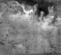
Here's my take on the Mars 3 "mountains" image. This is a conservative processing, consisting of manual histogram rebalance and hard median denoise. Finally I smoothed it with some blur and reduced resolution to the original 256 lines.
So I think that the details are real, not noise induced.
There are many possible matches around Argyre. I can fit those patterns with the mountains around the basin, and interpreting the bright curved line as a channel might narrow it down. -------------------- _______________________
www.astrosurf.com/nunes |
|
|
|
|
|
|
Oct 19 2014, 08:48 AM
Post
#203
|
|
 Member Group: Members Posts: 236 Joined: 5-June 08 From: Udon Thani Member No.: 4185 |
It's completely useless info, but the original Mars 3 orbit ranged out to more then 200 000 km from Mars.
Comet Siding Spring is passing Mars at some 120 000 km so inside the Mars 3 orbit making it potentially the closest man made object near the camet. Offcourse Mars 3 is long since dead and its orbit was so unstable that it probably has perturbed a lot since then so we basically have no way of knowing where the thing is by now (it might have crashed into Mars or re-entered solar orbit for all we know) but should we happen to observe something crashing into the comet then who knows 
|
|
|
|
| Guest_alex_k_* |
Oct 20 2014, 07:50 AM
Post
#204
|
|
Guests |
QUOTE (4th rock from the sun @ Oct 19 2014, 06:07 AM)  Here's my take on the Mars 3 "mountains" image. This is a conservative processing, consisting of manual histogram rebalance and hard median denoise. Finally I smoothed it with some blur and reduced resolution to the original 256 lines. So I think that the details are real, not noise induced. Nice picture. It would be interesting to take a look at result of the same procssing of the "horizon" image. But actually I don't see strong mismatches between our versions - there're no objects that contradict. Except of small details which were taken away by smoothing. |
|
|
|
| Guest_alex_k_* |
Oct 20 2014, 07:51 AM
Post
#205
|
|
Guests |
QUOTE (Phil Stooke @ Oct 19 2014, 02:27 AM) I had posted my opinion about this somewhere here on UMSF and elsewhere. The Mars 3 camera system was like Luna 13 with two cameras (not like Luna 9 with only one). The first part of the Luna 13 panorama was a view of the other camera (which did not work, we never got images from it) - so the first part of the Mars 3 panorama is almost certainly a view of the other camera, not the surface of Mars. Any structure in it is going to be some combination of glare and shading, possibly including reflections (but who knows what of), plus noise and scanning artifacts etc. We really should not look for the surface of Mars in the image. The original mission scientists would have grasped at anything real in that image, as it would have been an incredible feat, but even they denied it had any value as an image of Mars. Phil This version seems to be hardly probable. Cameras for Luna 13 and for Mars 3 where developed by A.Selivanov, and the experience of Luna 13 was taken into account in the next project. The schema when the scanning started from the second camera obviously was too risky to be repeated in the martian project. Here's an acticle written by Selivanov where he discusses about possible image from the Mars 3 lander: http://libgen.org/scimag5/10.1134/S0038094613030064.pdf . The technical information is very interesting, some assumptions are disputable. But he couldn't write such article if he knew that the camera started scanning from the second one. |
|
|
|
| Guest_alex_k_* |
Oct 20 2014, 08:03 AM
Post
#206
|
|
|
Guests |
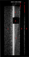
QUOTE (vikingmars @ Oct 18 2014, 08:21 PM) Dear alex_k, they were a lot of discussings about the processing of this famous "picture" and it depends on its orientation. Please, see posts : http://www.unmannedspaceflight.com/index.p...ost&p=52475 http://www.unmannedspaceflight.com/index.p...ost&p=52584 http://www.unmannedspaceflight.com/index.p...ost&p=52609 Thank you for the refferences. I think that you and 4th rock were right when you stretched the image to make it wider. The reason is follows. The camera on Mars 3 lander EA-046 was an advanced version of the Moon cameras YA-198 - they were almost the same but martian had higher scanning speed, 4 lines per second instead of 1. About the Moon camera it's known that it had two scanning modes: main (high resolution) and quick (the third mode was for technical purposeused for chooseing frame). In "quick mode" Moon panorama whould be transmitted in ~20 min againist 100 min in high resolution mode. I suppose that most reliable and probable implementation of "quick" mode was increasing speed of horisonal rotating of the scanner. If it is true, each line transmitted in quick mode has horizontal angle of view like 5 lines in standard hires mode - in other words, the camera missed about 4 lines. The question, which mode would be chosen, if the communication window was only about 1.5 minutes and there was no second chance? (see Geert's perfect posting http://www.unmannedspaceflight.com/index.p...t&p=199741) So the image's width should be stretched x5. About 79 lines and "no contrast". I suppose that the signal was misinterpreted by the scientists. The data from the lander were received and recorded by the orbiter and lately transmitted to the Earth - there was no direct retranslation. So "received 79 lines from the lander" is just an interpretation of a part of the information pack received from the orbiter which has width more than 270 lines. I enumerated the fragments of the source signal to reffer them. For my processing the image was filpped to be in proper orientation.
79 lines is the width of fragments 2-4. Fragment 1 has width of about 85 lines, and my statement that it contains complete received image. It's most quality fragment but like others transmitted with hard frequency deformations. It is not a white noise or telemetry, as offen interpreted. I suppose that fragments 6-8 also contain received image, but at very low level. So we have three replicants of the signal received from the lander. I processed, matched and composed them. My resulting image is a composition of 3 information layers. How is it possible that the information replicated so many times in the signal? It's known that the lander transmitted simultaneously by two independent channels, and the data were recorded by the orbiter on at least two tape recorders. My hypothesis is that the playback was looped when transmitting to the Earth for most reliability. Thus when the record finished it was continued from the end in reverse mode. Reversing line by line transmittion means rotating the image at 180 degrees. So the white left of fragments 2 and 4 and brightening at the right of fragment 1 have the same nature - it may be caused by the orbiter's going away over the horizon (by Geert) or by upcoming electrical degradation. I suppose that fragments 5-8 is a playback from the second recorder. |
|
|
|
|
|
|
Oct 20 2014, 10:36 AM
Post
#207
|
|
|
Member Group: Members Posts: 236 Joined: 5-June 08 From: Udon Thani Member No.: 4185 |
I would caution against trying to get too much out of this image, partly for reasons which have been mentioned here already.
Furthermore, as far as I know we don't even have absolute proof that this is actually the Mars 3 image at all! From what I remember the filmstrip was found by some Western TV crew somewhere in some archive in Moscow and they concluded that it had to be the missing Mars 3 imagte. Unfortunately so much time has passed that we can't be 100# sure whether this is really the case. We might be looking at something completely different, not related to Mars 3 at all. Remember, there is another picture which is said to be the Mars 3 recording (once again: said to be..). http://2.bp.blogspot.com/-3FjLiiL0Has/T5Qm...Mars3Signal.jpg This is supposed to be the picture as it appeared out of the teleprinter while the signal was received. IF (big IF) both pictures are true, then I wouldn't be surprised if the image you are using is in fact nothing but a photo-negative of a picture of that same teleprinter and it's printed paper. in that case the block you mark as 3 is nothing else but the stylus of that same photoprinter and some other artifacts might in fact be also parts of that printer! It was a historic event, so it is very well possible that they had a video camera trained on that teleprinter while the image was processed. I have never read any mention from former Soviet sources that the received signal was stored as a video signal. It was a digital signal which was processed and then printed on an oldfashioned teleprinter of the type seen in the picture. IF the original signal is anywhere preserved it would be on some magnetic tape. |
|
|
|
| Guest_alex_k_* |
Oct 20 2014, 11:27 AM
Post
#208
|
|
Guests |
QUOTE (Geert @ Oct 20 2014, 03:36 PM) I would caution against trying to get too much out of this image, partly for reasons which have been mentioned here already. Furthermore, as far as I know we don't even have absolute proof that this is actually the Mars 3 image at all! From what I remember the filmstrip was found by some Western TV crew somewhere in some archive in Moscow and they concluded that it had to be the missing Mars 3 imagte. Unfortunately so much time has passed that we can't be 100# sure whether this is really the case. We might be looking at something completely different, not related to Mars 3 at all. Remember, there is another picture which is said to be the Mars 3 recording (once again: said to be..). http://2.bp.blogspot.com/-3FjLiiL0Has/T5Qm...Mars3Signal.jpg This is supposed to be the picture as it appeared out of the teleprinter while the signal was received. IF (big IF) both pictures are true, then I wouldn't be surprised if the image you are using is in fact nothing but a photo-negative of a picture of that same teleprinter and it's printed paper. in that case the block you mark as 3 is nothing else but the stylus of that same photoprinter and some other artifacts might in fact be also parts of that printer! It was a historic event, so it is very well possible that they had a video camera trained on that teleprinter while the image was processed. I have never read any mention from former Soviet sources that the received signal was stored as a video signal. It was a digital signal which was processed and then printed on an oldfashioned teleprinter of the type seen in the picture. IF the original signal is anywhere preserved it would be on some magnetic tape. Dear Geert, I would address you to the BBC film "The Planets", episode 6, 22:15 and later. Selivanov and Marov show the signal's photo and comment it. About the another picture from printer, I suppose that it is not a received signal, but a result of early and not very successful processing. It would be great if possible to access the magnetic tape with the record, I tried without a result. But Selivanov told that for the article he used the original signal received from the lander. |
|
|
|
|
Oct 20 2014, 04:46 PM
Post
#209
|
|||
|
Member Group: Members Posts: 378 Joined: 21-April 05 From: Portugal Member No.: 347 |
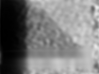
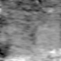
QUOTE (alex_k @ Oct 20 2014, 08:51 AM) Here's an acticle written by Selivanov where he discusses about possible image from the Mars 3 lander: http://libgen.org/scimag5/10.1134/S0038094613030064.pdf .... Don't remember reading this. Interesting read and processing, and that seems to be the actual data. Somewhat similar to the teleprinter output and not like the BBC fragment. I don't think the assumption of a tilted lander still holds. The Mars 3 on the surface photos we now have show it landed in the normal orientation. As for the BBC image fragment, it shows the AGC system working and adjusting the image brightness, just as explained in several sources. So it is a negative image, since the actual image brightness started at zero. After that you have some image scanning with the a periodic dropout (or obstruction at source) that creates your "3" square. More to the left the signal degenerates into noise and then disappears. It seems to come back briefly and then it's gone forever. All very consist with the "classical" interpretation of a failing transmitter. Here's what I got from the "horizon" image based on the above assumptions. I filled the missing data block by interpolation. My interpretation is that we are indeed seeing part of the lander.
But both images are hard to reconcile indeed. Here's what the same processing brings out on the teleprinter image:
It looks more like an orbital image, much like the "mountains" photo discussed before... -------------------- _______________________
www.astrosurf.com/nunes |
||
|
|
|
||
| Guest_alex_k_* |
Oct 21 2014, 05:21 AM
Post
#210
|
||
|
Guests |
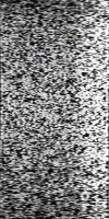
QUOTE (4th rock from the sun @ Oct 20 2014, 09:46 PM) As for the BBC image fragment, it shows the AGC system working and adjusting the image brightness, just as explained in several sources. So it is a negative image, since the actual image brightness started at zero. After that you have some image scanning with the a periodic dropout (or obstruction at source) that creates your "3" square. More to the left the signal degenerates into noise and then disappears. It seems to come back briefly and then it's gone forever. All very consist with the "classical" interpretation of a failing transmitter. How do you think, if the image was negative, why the "3" fragment (mirror flyback) is not negative? The white rectangular pulses at the left of the fragmnt are clearly distinctive, like Selivanov wrote. But the lines cannot be partially inverted! This interpretation seems contradictive. QUOTE (4th rock from the sun @ Oct 20 2014, 09:46 PM) Here's what I got from the "horizon" image based on the above assumptions. I filled the missing data block by interpolation. It is a very conservative processing. Take a look at my layers which I composed to the resulting image. They are matched to each other. 1. Fragment 1. (preprocessed source - stretched result)
|
||
|
|
|
||
| Guest_alex_k_* |
Oct 21 2014, 05:26 AM
Post
#211
|
|
Guests |
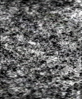
2. Fragments 2+4, rotated 180 deg.
[attachment=34048:test.png] [attachment=34049:layer2.png] 3. Fragments 6+7+8, rotated 180 deg (just stretched result) The second source http://fotki.yandex.ru/next/users/roborebe...274/view/959480 was used. [attachment=34050:layer3.png] The third layer is very extremal indeed, but it contains image. More quality sources are needed to refine this layer - the quiality of first two is enought. (limitation on attachments, continuing...) |
|
|
|
| Guest_alex_k_* |
Oct 21 2014, 05:34 AM
Post
#212
|
|
|
Guests |
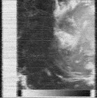
Without noised 3rd layer we get also appropriate composition.
[attachment=34051:m416_2.png] QUOTE (4th rock from the sun @ Oct 20 2014, 09:46 PM) But both images are hard to reconcile indeed. Here's what the same processing brings out on the teleprinter image:
I suppose that it was build using wrong assumptions but very strong noise reduction, that's why it's so hard to reconcile it. I think it was made of fragments 2+4 but they were combined in wrong order. |
|
|
|
|
|
|
Oct 21 2014, 02:29 PM
Post
#213
|
|
|
Member Group: Members Posts: 378 Joined: 21-April 05 From: Portugal Member No.: 347 |
Alex, can't really disagree (and I don't read russian, so my understanding of the sources is limited), but I think your results have too many "ifs".
If there are several fragments, if the fragments show the same data, if one of the fragments is inverted, etc, etc. So let's stay on the things we know. We know that the image starts with the autogain system gradually increases the gain up to a "standard" level. Therefore any fragments that don't show that have no image data. You have a point with the image not being a negative, since it's possible that the initial level was too high and the autogain has reduced the level and it's also possible that the "3" area is the mirror flyback. It's reasonable to consider that values during the flyback would be zero (but who know if they didn't insert a white signal for calibration + alignment? ) So as an alternative solution we get something like this:  The area "3" does seem like the end/start of each line, I've place it at top here just to be clear. But beyond the negative/positive possibilities I don't think we should speculate much. -------------------- _______________________
www.astrosurf.com/nunes |
|
|
|
| Guest_alex_k_* |
Oct 21 2014, 03:42 PM
Post
#214
|
|
Guests |
QUOTE (4th rock from the sun @ Oct 21 2014, 07:29 PM) Alex, can't really disagree (and I don't read russian, so my understanding of the sources is limited), but I think your results have too many "ifs". If there are several fragments, if the fragments show the same data, if one of the fragments is inverted, etc, etc. It's true, there're many "ifs". But the accordance of the fragments I can try to prove. QUOTE (4th rock from the sun @ Oct 21 2014, 07:29 PM) We know that the image starts with the autogain system gradually increases the gain up to a "standard" level. Therefore any fragments that don't show that have no image data. We know only that it's Selivanov's explaination. Can you show me the effect of "gradually increase" on a panorama of Luna-9 or Luna-13? QUOTE (4th rock from the sun @ Oct 21 2014, 07:29 PM) The area "3" does seem like the end/start of each line, You're right. So the areas "4" and "2" should be combined, but not by just omitting the area "2", but by swapping them ("end" and "start" should end and start the entire line). I suppose that the same error was made in the processing of the picture "from a teleprinter". If we remount it we'll get a kind of compliance with my image. |
|
|
|
|
Oct 21 2014, 04:51 PM
Post
#215
|
||
|
Member Group: Members Posts: 378 Joined: 21-April 05 From: Portugal Member No.: 347 |
"We know only that it's Selivanov's explaination. Can you show me the effect of "gradually increase" on a panorama of Luna-9 or Luna-13?"
I can't. But I haven't seen the raw data* from the Lunas, only the final panoramas How do you explain it if it's not the autogain system? - Mirror flyback? - Grayscale calibration at the start of each line? - Autogain of the orbiter's receiver ? For the sake of discussion, let me present a modern HF-Fax analog image:
This is what an analog image transmission looks like. Its single side band AM with the image data encoded as image tones varying from black at 1500 Hz and peak white at 2300 Hz. Some black/white or grayscale calibration elements are usually present . We know from Luna 9 that the Soviet system was similar. Don't know if some raw data exists for that, but perhaps it might help to clarify things. * This information from Jodrell Bank about Luna 9 is helpful: " The international facsimile standard is that the White/black transition corresponds to a a change in audio frequency between 1.5 to 2.3 kHz, while the Luna 9 transmissions used a change from 1.2 to 2.0 kHz. The difference in horizontal/vertical ratio was sometimes given as a factor 2 and sometimes as a factor 2.5 . The picture signals were transmitted on a subcarrier with maximum deviation of 2 kHz. The synchronization signal for the pictures (start of each line?) was a tone with the frequency 1.1 kHz (24). The lunar panoramas consisted of vertical lines with 500 elements (each 3.6 minutes of arc wide) and the 360 degree view around the horizon consisted of 6000 such lines" (from http://www.jb.man.ac.uk/history/tracking/part2.html) -------------------- _______________________
www.astrosurf.com/nunes |
|
|
|
|
|
|

|
Lo-Fi Version | Time is now: 30th May 2024 - 12:29 AM |
|
RULES AND GUIDELINES Please read the Forum Rules and Guidelines before posting. IMAGE COPYRIGHT |
OPINIONS AND MODERATION Opinions expressed on UnmannedSpaceflight.com are those of the individual posters and do not necessarily reflect the opinions of UnmannedSpaceflight.com or The Planetary Society. The all-volunteer UnmannedSpaceflight.com moderation team is wholly independent of The Planetary Society. The Planetary Society has no influence over decisions made by the UnmannedSpaceflight.com moderators. |
SUPPORT THE FORUM Unmannedspaceflight.com is funded by the Planetary Society. Please consider supporting our work and many other projects by donating to the Society or becoming a member. |
|