ROVER WHEELS: Monitoring changes over time, NOTE: Read back through the thread to avoid repeating misconceptions |

  |
ROVER WHEELS: Monitoring changes over time, NOTE: Read back through the thread to avoid repeating misconceptions |
 Jan 17 2014, 01:55 AM Jan 17 2014, 01:55 AM
Post
#151
|
||||
 Administrator  Group: Admin Posts: 5172 Joined: 4-August 05 From: Pasadena, CA, USA, Earth Member No.: 454 |
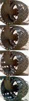
I'm trying to get a handle on wheel geography in order to interpret the survey images and look for changes. These are all from the sol 513 MAHLI imaging. I count 20 inter-tread areas (where the punctures are forming) between treads. Because the Morse code makes such a good landmark, I am counting upward and downward from those spots to name the inter-tread areas, 10 up and 10 down. I'm noting locations of tears and punctures as they are closer to the rover (medial) or farther from the rover (lateral) or in between (central). So far I've just looked at the right-side wheels. Here's what I've found in this one set, keeping in mind that the RF wheel was incompletely surveyed. There were some spots I wasn't sure about. Now I need to complete the survey on the left side, and then compare back in time to try to note any others that I missed on this survey, and to try to put some constraints on when the tears initialized and worsened.
RF 6 down - big puncture, center
RM 5 down - small tear, center 9 down - big puncture, medial 10 down - small tear, medial 6 up - small tear, center
RR - nothing major
-------------------- My website - My Patreon - @elakdawalla on Twitter - Please support unmannedspaceflight.com by donating here.
|
|||
 |
 
|
|||
|
Jan 17 2014, 03:19 AM
Post
#152
|
|
|
Solar System Cartographer Group: Members Posts: 10166 Joined: 5-April 05 From: Canada Member No.: 227 |
Right-hand image, second one down: Number 8 has a T-shaped mark just to the left of the number.
Next image down: that same T-shaped mark is on the space numbered 9. I don't see any other numbering errors. Phil -------------------- ... because the Solar System ain't gonna map itself.
Also to be found posting similar content on https://mastodon.social/@PhilStooke Maps for download (free PD: https://upload.wikimedia.org/wikipedia/comm...Cartography.pdf NOTE: everything created by me which I post on UMSF is considered to be in the public domain (NOT CC, public domain) |
|
|
|
|
Jan 17 2014, 04:00 AM
Post
#153
|
||||
|
Administrator Group: Admin Posts: 5172 Joined: 4-August 05 From: Pasadena, CA, USA, Earth Member No.: 454 |
Thanks, I fixed that.
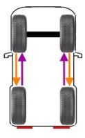
Here's the rest. I wonder why the left middle and left front wheels have suffered so much more than the others, and why the two rear wheels appear to have escaped injury so far. LR Nothing major
LM 10 down -- big puncture, central 10 up - puncture, central 9 up -- 3 punctures, central 8 up -- "seagull" shape tear, central 6 up -- puncture, central 4 up -- very small tear, medial
LF 1 down -- huge rip, central, & tear, medial 2 down - small tear, central 4 down - small puncture, lateral 5 down - small tear, central 6 down - small puncture, central 10 down -- 2 small punctures, central 10 up -- small tear, central 5 up - small tear, central 4 up -- tear, lateral 2 up -- big puncture, central
-------------------- My website - My Patreon - @elakdawalla on Twitter - Please support unmannedspaceflight.com by donating here.
|
|||
|
|
|
|||
|
Jan 17 2014, 05:29 AM
Post
#154
|
|
 Senior Member Group: Members Posts: 3419 Joined: 9-February 04 From: Minneapolis, MN, USA Member No.: 15 |
As has been pointed out, the MSL mobility testbed unit displays similar rips and tears in the wheels. It might be instructive to see the current status of the testbed wheels, along with a rough history of the number of meters it was driven and over what surfaces. I recall seeing video of the testbed recorded well before Curiosity landed that shows significant ripping and tearing in its wheels, so it must not take a huge amount of driving for these things to appear.
For the testbed experience to be truly applicable to the asset on Mars, I imagine the weight of the testbed would have to be roughly one-third of the actual MSL. I recall that the MER mobility testbed was weighted in this manner, I'm assuming MSL's was, too. -the other Doug -------------------- The trouble ain't that there is too many fools, but that the lightning ain't distributed right. -Mark Twain
|
|
|
|
|
Jan 17 2014, 05:35 AM
Post
#155
|
|
|
Administrator Group: Admin Posts: 5172 Joined: 4-August 05 From: Pasadena, CA, USA, Earth Member No.: 454 |
The soil in the testbed area doesn't bear a lot of similarity to the exposed, angular rock of the Gale landing site.
-------------------- My website - My Patreon - @elakdawalla on Twitter - Please support unmannedspaceflight.com by donating here.
|
|
|
|
|
Jan 17 2014, 05:48 AM
Post
#156
|
|
|
Senior Member Group: Members Posts: 3419 Joined: 9-February 04 From: Minneapolis, MN, USA Member No.: 15 |
Okay. Well, hey, it was a thought. Might still be interesting to compare the testbed wheels to Curiosity's, if just see if the wear and tear on this wheel design is inherent in the design and will occur pretty much irrespective of the surface conditions, or whether a surface with a larger admixture of sharp-edged stones will (as common sense would suggest) cause more rips and tears.
Again, I have no doubt that the wheels will work fine even if large sections of the thin aluminum end up getting ripped and torn. As with many of us, I'm sure, I just find this an interesting engineering exercise. (The absolute worst image I have is of Curiosity sort of humping up and down if a large piece of metal ends up sticking out of one of the wheels, a dynamic I find unlikely considering that even if a piece were to catch on a rock and rip radially outwards, the wheel motion would then tend to push it harmlessly back in towards the wheel hub.) -the other Doug -------------------- The trouble ain't that there is too many fools, but that the lightning ain't distributed right. -Mark Twain
|
|
|
|
|
Jan 17 2014, 09:20 AM
Post
#157
|
||
 Senior Member Group: Members Posts: 1088 Joined: 19-February 05 From: Close to Meudon Observatory in France Member No.: 172 |
QUOTE (elakdawalla @ Jan 17 2014, 05:00 AM)  Thanks a lot Emily for those much informative pictures ! Now we can see, thanks to your good processings, that the LR and RR wheels have much less rips, tears and punctures than the LF and RF wheels, it means that the front wheels are taking all the bad shocks, maybe crushing some pebbles and flattening the ground, somewhat "paving the way" for the rear wheels. Thus, if the situation really worsens for the front wheels, a good solution would be to turn the rover 180° and drive backwards. Then, the "new" front wheels (the former LR and RR wheels) will "pave the way" for us... much like reversing the tyres on your car 
|
|
|
|
|
|
|
Jan 17 2014, 03:20 PM
Post
#158
|
|
 Senior Member Group: Members Posts: 4247 Joined: 17-January 05 Member No.: 152 |
Yeah, I could believe that the rear wheels are somewhat protected, in that some sharp protruding rocks are pushed or rotated down by the front and middle wheels. Conceivably there could also be some difference due to the asymmetric rocker/bogey design.
|
|
|
|
|
Jan 17 2014, 03:32 PM
Post
#159
|
|
|
Senior Member Group: Members Posts: 2517 Joined: 13-September 05 Member No.: 497 |
QUOTE (dvandorn @ Jan 16 2014, 10:29 PM) For the testbed experience to be truly applicable to the asset on Mars, I imagine the weight of the testbed would have to be roughly one-third of the actual MSL. Depends on what you mean by testbed. The VSTB (which Doug has posted pictures of) is a flight-like rover and probably has a mass similar to that of the flight system (I don't know if it has ballast for the RTG or not.) The "scarecrow" is 1/3rd mass but I don't know what the state of its wheels are/were. Of course some of the dynamics depend on mass, not weight, so there's no way to perfectly mimic the behavior on Mars on Earth. -------------------- Disclaimer: This post is based on public information only. Any opinions are my own.
|
|
|
|
|
Jan 17 2014, 11:09 PM
Post
#160
|
|
 Member Group: Members Posts: 691 Joined: 21-December 07 From: Clatskanie, Oregon Member No.: 3988 |
QUOTE (elakdawalla @ Jan 16 2014, 08:00 PM) I wonder why the left middle and left front wheels have suffered so much more than the others, and why the two rear wheels appear to have escaped injury so far. I'm kind of thinking since the Arm interfaces on the left side, once the arm is deployed, mass is shifting and putting more pressure on that wheel. If any sharp rocks are under the wheel, I wonder if that will cause a puncture because of that shifting mass as the arm is moving. Or another idea is while driving, since the heavy turret and shoulder joint of the arm are both on that side in a stowed config, perhaps that puts more weight on that wheel? |
|
|
|
|
Jan 17 2014, 11:39 PM
Post
#161
|
|
|
Founder Group: Chairman Posts: 14432 Joined: 8-February 04 Member No.: 1 |
It's big heavy arm and a lot of torque there if it's stuck out....but....if the rover moved enough for a wheel to get punctures during that process... we would see it in imagery of pre/post arm deployment. We've seen some motion...but only a tiny bit.
|
|
|
|
|
Jan 20 2014, 05:25 PM
Post
#162
|
|
|
Senior Member Group: Members Posts: 2517 Joined: 13-September 05 Member No.: 497 |
QUOTE (James Sorenson @ Jan 17 2014, 04:09 PM) Or another idea is while driving, since the heavy turret and shoulder joint of the arm are both on that side in a stowed config, perhaps that puts more weight on that wheel? I think this is an interesting speculation, but given that the whole vehicle was hung from the descent stage with the arm stowed like this, I'd suspect it was fairly well-balanced and not much heavier on one side than the other. But I don't know for sure. BTW, I put together the LEGO model of the rover yesterday. I can't say enough good things about it as a visualization tool for both the suspension and the arm. Highly recommended! http://shop.lego.com/en-US/NASA-Mars-Scien...ity-Rover-21104 -------------------- Disclaimer: This post is based on public information only. Any opinions are my own.
|
|
|
|
|
Jan 20 2014, 05:34 PM
Post
#163
|
|
|
Senior Member Group: Members Posts: 2517 Joined: 13-September 05 Member No.: 497 |
QUOTE (djellison @ Jan 17 2014, 04:39 PM) It's big heavy arm... Not doubting Doug at all, but just to put some numbers on that: according to http://www.esmats.eu/esmatspapers/pastpape...ling.pdf the arm mass without the turret is 67 kg, and the turret weighs 34 kg. So it is quite heavy, and I could imagine that it does load up some of the wheels pretty significantly in some poses. I'm not certain if the high-time-res rover orientation data makes it into the SPICE kernels, but if it does, it might be interesting to visualize how much movement the rover actually undergoes when it's nominally stationary. -------------------- Disclaimer: This post is based on public information only. Any opinions are my own.
|
|
|
|
|
Jan 20 2014, 11:30 PM
Post
#164
|
|
 Member Group: Members Posts: 495 Joined: 12-February 12 Member No.: 6336 |
QUOTE (mcaplinger @ Jan 20 2014, 06:34 PM) Not doubting Doug at all, but just to put some numbers on that: according to http://www.esmats.eu/esmatspapers/pastpape...ling.pdf the arm mass without the turret is 67 kg, and the turret weighs 34 kg. So it is quite heavy, and I could imagine that it does load up some of the wheels pretty significantly in some poses. That's the weight on Earth right? On Mars that give me a weight of 37,47 kg. While the weight is lower, the mass being the same so agreed, it is quite massive also compared to the ones mounted on the predecessor rovers. |
|
|
|
|
Jan 20 2014, 11:38 PM
Post
#165
|
|
|
Senior Member Group: Members Posts: 2517 Joined: 13-September 05 Member No.: 497 |
QUOTE (TheAnt @ Jan 20 2014, 04:30 PM) That's the weight on Earth right? A kilogram is a measure of mass, not weight (I misspoke in my post; the turret mass is 34 kg). The arm has the same mass on Mars that it does on Earth. You say this yourself but I'm not certain what your point is. That said, the resulting pressure on the wheel surface would be lower on Mars. Of course, something is making holes in the wheels; it's either pressure (depends on weight); impact forces (depends more on mass); or some dynamic combination. -------------------- Disclaimer: This post is based on public information only. Any opinions are my own.
|
|
|
|
|

|
Lo-Fi Version | Time is now: 23rd May 2024 - 06:21 PM |
|
RULES AND GUIDELINES Please read the Forum Rules and Guidelines before posting. IMAGE COPYRIGHT |
OPINIONS AND MODERATION Opinions expressed on UnmannedSpaceflight.com are those of the individual posters and do not necessarily reflect the opinions of UnmannedSpaceflight.com or The Planetary Society. The all-volunteer UnmannedSpaceflight.com moderation team is wholly independent of The Planetary Society. The Planetary Society has no influence over decisions made by the UnmannedSpaceflight.com moderators. |
SUPPORT THE FORUM Unmannedspaceflight.com is funded by the Planetary Society. Please consider supporting our work and many other projects by donating to the Society or becoming a member. |
|