QUOTE
Looks very promising despite the 'terraced' appearance in much of the image (a consequence of an 8 bit DEM?)
no, that is an artifact from a fast and not so good contrast bump on the low contrast map . At this stage i am not worried after all the screen shot is a 4096x2048 resize of the 16384x8192 map i am making .
QUOTE
As an example, for image N1507742440_2.IMG of Dione the correct direction is (0.303693, -0.205793, 0.930279) but I get much better results using (0.5,0.2,0.6).
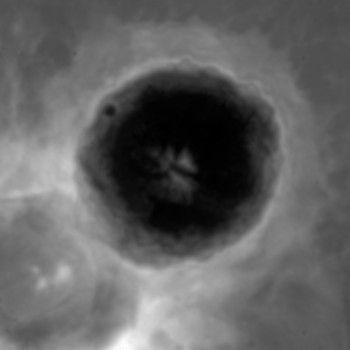
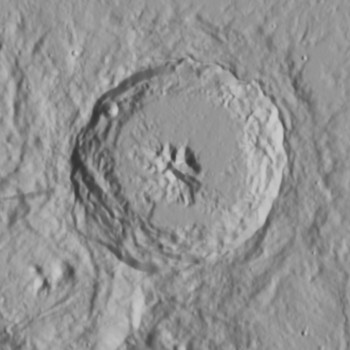
for this image i am using this ( measurementsare on the image )
-- oops i miss typed --
Click to view attachment from the center 0.2 up and 1.0 over( right ) and 0.5 out from the screen is the height
-- correction --
on the photo should be ( 1.0 ,0.2,0.5)
QUOTE
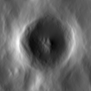
Big craters are often too shallow in the resulting DEMs, requiring postprocessing in Photoshop (or combining the Cyclops DEM with a stereo DEM).
i have seen that too , that is why i posted above ( a few posts) that i have been editing , by hand, the craters
there are very predictable spots that need help
Click to view attachmentalso the second hi-pass is removing some of the depth in the hole but at the same time it is getting ride of the left to right slope
as seen in Nirgal's post
http://www.thethirdplanet.de/mars_gallery/...okrates_sfs.jpgthe one on the right is like the ply / normal map from cyclops , and that second hi-pass filter flattens the image .
-- i or we or all of us need to find a better solution --
but considering there is not much of a choice
the pc2d ( from 2004 )
-gimp-
shapefs-1.2.0.0-20051020.tar.gz ( this dos not work well and needs a very old version of gimp )
i have collected a few OLD things and they do build
linear.cpp
-- excerpt --
CODE
/****************************************************************************
NAME: linear.cpp -- Performs shape from shading using
linear FFT based algorithm
SYNOPSIS: linear inImage inFmt sunElevAngle sunAzimAngle d -f fltFrq outFmt outDem
Example: linear spot128.dat 2 19.3 287.2 2.5 -f 0 2 ts_dem.dat
DESCRIPTION: This program performs linear shape-from-shading
ALGORITHM REFERENCES:
Liu, H. "Derivation of surface topography and terrain parameters
from single satellite image using shape-from-shading technique"
in Computers & Geosciences
BUGS:
Compiling on SGI:
CC -Ddebug=0 -g -o linear linear.cpp linear_sfs.cpp fft2d.cpp imageio.cpp stopwatch.cpp -LANG:std -lm
Compiling on SUN:
CC -Ddebug=0 -g -o linear linear.cpp linear_sfs.cpp fft2d.cpp imageio.cpp stopwatch.cpp -lm
or mini.cpp
CODE
/****************************************************************************
NAME: mini.c - Performs shape from shading using minimization algorithm
SYNOPSIS: mini inName inFmt sunElevAngle sunAzimAngle lamda iterNum -d initDemName outFmt outName
Example 1:mini spot128.dat 2 19.3 287.2 1.5 50 2 ts_dem.dat
ALGORITHM REFERENCES:
Liu, H. "Derivation of surface topography and terrain parameters
from single satellite image using shape-from-shading technique"
in Computers & Geosciences
Compiling on SGI:
CC -Ddebug=0 -g -o mini mini.cpp mini_sfs.cpp fft2d.cpp imageio.cpp stopwatch.cpp -LANG:std -lm
Compiling on SUN:
CC -Ddebug=0 -g -o mini mini.cpp mini_sfs.cpp fft2d.cpp imageio.cpp stopwatch.cpp -lm
************************************************************/
the two above are from a zip called
v29-10-03.zip this was from a paper - google found the zip but not the paper
(h??p://207.176.140.93/documents/oldftp/VOL29/)
and then cyclops . So not to much of a choice here
in a few( or many,many) years there will be Nirgal's . If all the patent an IP issues can be solved