3D shape, cartography, and geoid of Comet 67P C-G |

3D shape, cartography, and geoid of Comet 67P C-G |
 Aug 6 2014, 02:11 PM Aug 6 2014, 02:11 PM
Post
#1
|
|
|
Solar System Cartographer  Group: Members Posts: 10166 Joined: 5-April 05 From: Canada Member No.: 227 |
Explorer 1 said:
"A 2D map of C-G seems like a tough order; the projection math alone..." Don't worry! If you can put a grid on the surface (as we have seen already), you can warp that grid into any map projection you like. Mapping will be no huge problem - in fact I expect they have a rough one already (I've been playing with one myself). Phil -------------------- ... because the Solar System ain't gonna map itself.
Also to be found posting similar content on https://mastodon.social/@PhilStooke Maps for download (free PD: https://upload.wikimedia.org/wikipedia/comm...Cartography.pdf NOTE: everything created by me which I post on UMSF is considered to be in the public domain (NOT CC, public domain) |
 |
 
|
 |
|
Aug 6 2014, 02:44 PM
Post
#2
|
|
|
Junior Member Group: Members Posts: 30 Joined: 6-September 12 From: Denver Member No.: 6641 |
It would appear that the neck is an "erosional" feature (not sure if erosion is the right word), and maybe not the contact boundary between 2 separate bodies. At some point in the future, the neck will sublime away and the comet will split in two.
|
|
|
|
|
Aug 6 2014, 03:47 PM
Post
#3
|
|
 Member Group: Members Posts: 593 Joined: 20-April 05 Member No.: 279 |
QUOTE (acastillo @ Aug 6 2014, 03:44 PM)  It would appear that the neck is an "erosional" feature... Gravity must be very low there, caught as it is between two lumps o' rock. A higher chance for material to be lost, maybe? Andy |
|
|
|
|
Aug 6 2014, 04:06 PM
Post
#4
|
|
 Senior Member Group: Members Posts: 1639 Joined: 5-March 05 From: Boulder, CO Member No.: 184 |
QUOTE (Explorer1 @ Aug 6 2014, 11:43 AM) A 2D map of C-G seems like a tough order; the projection math alone...  Interesting though that a unique coordinate system (projection) is possible as seen in the rotating map. None of the overhangs appear to wrap back on themselves as seen from the central projection point. Thus a 2D map should be possible with access to the shape model (as Phil alluded to earlier). -------------------- Steve [ my home page and planetary maps page ]
|
|
|
|
|
Aug 6 2014, 04:46 PM
Post
#5
|
|
 Member Group: Members Posts: 495 Joined: 12-February 12 Member No.: 6336 |
QUOTE (acastillo @ Aug 6 2014, 04:44 PM) It would appear that the neck is an "erosional" feature (not sure if erosion is the right word), and maybe not the contact boundary between 2 separate bodies. At some point in the future, the neck will sublime away and the comet will split in two. I concur, not that we have a final word yet but I do tend to think the shape is from melting and erosion, rather than 2 objects that have merged since that is a less likely scenario. @AndyG: Gravity is nearly negligible, gas pressure define this environment with sublimation and active geysers, though I wonder if the latter could create a static charge. |
|
|
|
|
Aug 6 2014, 04:52 PM
Post
#6
|
|
|
Senior Member Group: Members Posts: 2346 Joined: 7-December 12 Member No.: 6780 |
QUOTE (scalbers @ Aug 6 2014, 06:06 PM) Interesting though that a unique coordinate system (projection) is possible as seen in the rotating map. ... That's possible with any simply connected object (no "handle-shaped holes") in 3d via a homeomorphism (continuous map). For objects with holes, like doughnuts different coordinate systems are needed. The shape of the nucleus is strange, but fortunately not that strange. |
|
|
|
|
Aug 6 2014, 05:02 PM
Post
#7
|
|
|
Senior Member Group: Members Posts: 1639 Joined: 5-March 05 From: Boulder, CO Member No.: 184 |
QUOTE (Gerald @ Aug 6 2014, 04:52 PM) That's possible with any simply connected object (no "handle-shaped holes") in 3d via a homeomorphism (continuous map). ... Sounds good, though it seems to me that C-G would be more straightforward than some other simply connected objects. A latitude/longitude with respect to C-Gs center of gravity appears to be possible as a "planetocentric" or "cometocentric" coordinate. It would be a simple tracing of rays emanating from the central point and then intersecting the surface. Each ray has just a single intersection with the surface. -------------------- Steve [ my home page and planetary maps page ]
|
|
|
|
|
Aug 6 2014, 05:23 PM
Post
#8
|
|
|
Senior Member Group: Members Posts: 2346 Joined: 7-December 12 Member No.: 6780 |
QUOTE (scalbers @ Aug 6 2014, 07:02 PM) ...Each ray has just a single intersection with the surface. As long as there are no relevant overhangs (in the sense of the rays). I'm not quite sure whether this holds for the comet. It could become a little more tricky. |
|
|
|
|
Aug 6 2014, 05:38 PM
Post
#9
|
|
|
Senior Member Group: Members Posts: 1639 Joined: 5-March 05 From: Boulder, CO Member No.: 184 |
QUOTE (Gerald @ Aug 6 2014, 05:23 PM) As long as there are no relevant overhangs (in the sense of the rays). I'm not quite sure whether this holds for the comet. It could become a little more tricky. Good point. A closer look at the recent animation shows a few localized breaks in the grid lines. This correlates with some local topography that has addtional intersection points with the rays pointing at the center of gravity. Perhaps one would have to filter out these bumps in a shape model to come up with a reference shape that could be specified using a cometocentric coordinate. Then the actual surface can be compared with normals to this reference shape. -------------------- Steve [ my home page and planetary maps page ]
|
|
|
|
|
Aug 8 2014, 07:47 PM
Post
#10
|
|
|
Member Group: Members Posts: 107 Joined: 1-August 14 Member No.: 7227 |
QUOTE (acastillo @ Aug 6 2014, 03:44 PM) It would appear that the neck is an "erosional" feature (not sure if erosion is the right word), and maybe not the contact boundary between 2 separate bodies. At some point in the future, the neck will sublime away and the comet will split in two. Eyewitnessing it will be simply amazing. On the opposite side, mapping an evolving body will be a pain! |
|
|
|
|
Aug 8 2014, 08:04 PM
Post
#11
|
|
|
Solar System Cartographer Group: Members Posts: 10166 Joined: 5-April 05 From: Canada Member No.: 227 |
Not a pain, it just means the cartographers have long-term employment!
Phil -------------------- ... because the Solar System ain't gonna map itself.
Also to be found posting similar content on https://mastodon.social/@PhilStooke Maps for download (free PD: https://upload.wikimedia.org/wikipedia/comm...Cartography.pdf NOTE: everything created by me which I post on UMSF is considered to be in the public domain (NOT CC, public domain) |
|
|
|
|
Aug 8 2014, 08:06 PM
Post
#12
|
|
|
Senior Member Group: Members Posts: 2086 Joined: 13-February 10 From: Ontario Member No.: 5221 |
Wouldn't the two lobes just gradually come back together together as the neck erodes, if their mass remains the same? Unless a decrease in radius forces C-G to rotate faster and faster (I guess we'll find out soon!)
|
|
|
|
|
Aug 8 2014, 10:00 PM
Post
#13
|
|
|
Solar System Cartographer Group: Members Posts: 10166 Joined: 5-April 05 From: Canada Member No.: 227 |
I think you're right, the lobes would collapse together as the neck was eroded.
Phil -------------------- ... because the Solar System ain't gonna map itself.
Also to be found posting similar content on https://mastodon.social/@PhilStooke Maps for download (free PD: https://upload.wikimedia.org/wikipedia/comm...Cartography.pdf NOTE: everything created by me which I post on UMSF is considered to be in the public domain (NOT CC, public domain) |
|
|
|
|
Aug 8 2014, 10:05 PM
Post
#14
|
|
|
Junior Member Group: Members Posts: 88 Joined: 8-May 14 Member No.: 7185 |
I believe the centrifugal forces at the rotational rate of ~ 1 revolution per day are stronger than the combined gravitational attraction of the two lobes. If the neck breaks they would come apart, as I see it. Would be interesting to see calculations of the eventuality.
|
|
|
|
|
Aug 8 2014, 10:17 PM
Post
#15
|
|
|
Founder Group: Chairman Posts: 14432 Joined: 8-February 04 Member No.: 1 |
Rotation rate is 12.7 hours. The circumference drawn by the 4km length of the comet ( a 2km radius ) is 12.6 km
So very roughly - it's doing 1km/hr or 0.28m/sec. V^2/r is thus 0.000039 m/sec^2 Surface gravity is approximated as 10^-3 m/sec^2 3 orders of magnitude higher than the centripetal acceleration due to rotation. Thus no - they would not fly apart. They would collapse together. |
|
|
|
|
Aug 8 2014, 10:20 PM
Post
#16
|
|
|
Merciless Robot Group: Admin Posts: 8784 Joined: 8-December 05 From: Los Angeles Member No.: 602 |
The key variable between these scenarios is mass, which will presumably be known in time to a high degree of precision. (Probably not nearly as soon as it would be for a symmetrical body; Rosetta's navigators are probably gonna have an interesting time for quite a few orbits until they get a handle on the mass distribution of C-G).
EDIT: Whups, cancel that. What Doug said. Obviously the system's mass is constrained well within an order of magnitude already. -------------------- A few will take this knowledge and use this power of a dream realized as a force for change, an impetus for further discovery to make less ancient dreams real.
|
|
|
|
|
Aug 8 2014, 10:22 PM
Post
#17
|
|
|
Senior Member Group: Members Posts: 3516 Joined: 4-November 05 From: North Wales Member No.: 542 |
Every irregular object eroded from the outside must eventually form a neck which breaks and the two parts will settle together, tumbled or not. How would they get the energy to fly apart again?
|
|
|
|
|
Aug 8 2014, 10:28 PM
Post
#18
|
|
|
Merciless Robot Group: Admin Posts: 8784 Joined: 8-December 05 From: Los Angeles Member No.: 602 |
Could acquire more angular momentum from impacts over time; then the variable would become the shear strength of the 'neck'. But as Doug observed, it's not spinning fast enough.
-------------------- A few will take this knowledge and use this power of a dream realized as a force for change, an impetus for further discovery to make less ancient dreams real.
|
|
|
|
|
Aug 8 2014, 10:37 PM
Post
#19
|
|
|
Founder Group: Chairman Posts: 14432 Joined: 8-February 04 Member No.: 1 |
If it were rotating fast enough to displace the two halves if the 'neck' were to disappear....then it would also be rotating fast enough to rip itself to shreds.
What I have in essence done is prove that the comet can exist (which is somewhat self evident) |
|
|
|
|
Aug 8 2014, 10:42 PM
Post
#20
|
|
 Member Group: Members Posts: 267 Joined: 5-February 06 Member No.: 675 |
I'm not convinced by the emerging consensus that the neck is an erosional feature. It seems to me that the neck is near a gravitational low (i.e., "downhill" from the rest of the comet) and any loose material near the comet would be likely to settle there.
In previous passes by the Sun the comet would eject both volatile gases and particles of solids; some of them might not achieve escape velocity. The volatiles would be reheated on the surface and escape again but we would expect the solids to settle back in the lowest point, the comet's neck. This model predicts a dustier area near the neck with a comparatively lower concentration of volatiles. We'll see what turns up but I'm not a geologist so what do I know. Steve M |
|
|
|
|
Aug 8 2014, 11:10 PM
Post
#21
|
|
|
Founder Group: Chairman Posts: 14432 Joined: 8-February 04 Member No.: 1 |
QUOTE (SteveM @ Aug 8 2014, 03:42 PM) I'm not convinced by the emerging consensus that the neck is an erosional feature It's where the bulk of activity appears to be http://sci.esa.int/rosetta/54471-comet-act...-2-august-2014/ |
|
|
|
|
Aug 9 2014, 12:08 AM
Post
#22
|
|
|
Founder Group: Chairman Posts: 14432 Joined: 8-February 04 Member No.: 1 |
QUOTE (Gerald @ Aug 8 2014, 03:36 PM) Hmm, according to the Wikipedia version, the escape velocity is estimated to 0.46 m/s, corresponding to about 0.33 m/s for a circular orbit. So I'd say within the current uncertainty, respecting the rotation, the resulting surface gravity at the parts most distant to the center of mass is about zero. No - the centripetal acceleration is 4 orders of magnitude less than the escape velocity. |
|
|
|
|
Aug 9 2014, 01:11 AM
Post
#23
|
|
|
Newbie Group: Members Posts: 4 Joined: 2-April 14 Member No.: 7160 |
QUOTE (Gerald @ Aug 8 2014, 01:36 PM) Hmm, according to the Wikipedia version, the escape velocity is estimated to 0.46 m/s, corresponding to about 0.33 m/s for a circular orbit. So I'd say within the current uncertainty, respecting the rotation, the resulting surface gravity at the parts most distant to the center of mass is about zero. A significantly more compact body with the same angular momentum would be torn apart. This opens a scenario almost opposing the contact binary approach, meaning head and body could have been broken apart already by centrifugal pseudo-force, and kept together by the stretched "neck", which would give the "rubber" duck metaphor more sense than originally anticipated. This way the inner of the comet would be exposed at the neck. Additional momentum could have been provided by impacts or by YORP. Back of the envelope: Gravity /centripetal ~ GM/r^2//V^2/r ~ GpP^2 where G = grav constant of 6.67x 10^-11 (mks), p = density ~ 10^3 (mks) and P = period ~4.6x10^4 sec. Ratio ~ 10^2 Gravity wins hands down. Tidal forces are insufficient. Adjustments to Fg due to odd shape may cause ratio be somewhat less, but increasing density will go the other way. |
|
|
|
|
Aug 9 2014, 01:28 AM
Post
#24
|
|
|
Member Group: Members Posts: 890 Joined: 18-November 08 Member No.: 4489 |
QUOTE (jgoldader @ Aug 7 2014, 09:24 AM) Any chance of Gaspra? I did some work on that back before the Galileo flyby; it would be great to print it out. Thanks! Jeff there is a 3d mesh ( low-res) for gaspra http://forum.celestialmatters.org/viewtopi...p?f=4&t=636  my g-drive link to the mesh https://drive.google.com/file/d/0B6ZYAd08tZ...dit?usp=sharing QUOTE Not a pain, it just means the cartographers have long-term employment! Phil well for 67P a Simplecylindrical map is " out the window" the vid on youtube looks to be using a Simplecylindrical map https://www.youtube.com/watch?v=CNGu7KbXzOs you can tell by the STRETCHED green dots that look like lines But a "cubemap " would work fairly well |
|
|
|
|
Aug 9 2014, 01:42 AM
Post
#25
|
||
 Member Group: Members Posts: 219 Joined: 14-November 11 From: Washington, DC Member No.: 6237 |
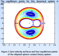
I had been curious about the gravity field so was googling about... this poster shows some of the weirdness of "which way is up" in a simplified contact binary scenario. It makes perfect sense, but I never considered that there could be the equivalent of Lagrange points near these bodies. Close-in "orbits" would certainly not be circular, even halos are possible. And the details near the neck... hard to know.
http://www.lr.tudelft.nl/fileadmin/Faculte...nglang_Feng.pdf snip:
|
|
|
|
|
|
|
Aug 9 2014, 01:53 AM
Post
#26
|
|
 Member Group: Members Posts: 796 Joined: 27-February 08 From: Heart of Europe Member No.: 4057 |
According to my calculations gravity/centripetal ratio for r=2000 m and vrot=0.28 m/s is G/a=0.0143*Ro (density)
Comets could be very fluffy so density can be between 100 to 1400 kg/m3. Ratio is then 1.5 to 20× (not ~100 or ~1000). -------------------- |
|
|
|
|
Aug 9 2014, 02:10 AM
Post
#27
|
|
|
Senior Member Group: Members Posts: 2346 Joined: 7-December 12 Member No.: 6780 |
QUOTE (JCG @ Aug 9 2014, 03:11 AM) Back of the envelope: Gravity /centripetal ~ GM/r^2//V^2/r ~ GpP^2 where G = grav constant of 6.67x 10^-11 (mks), p = density ~ 10^3 (mks) and P = period ~4.6x10^4 sec. Ratio ~ 10^2 Gravity wins hands down. Tidal forces are insufficient. This would be bad for Philae, so I've looked, where the discrepancy may come from. One reason is -- if I calculated correctly -- a factor of 1 / 3π for the density calculation in the spherical case. The other one is the estimated density, which has been estimated as 10^2 kg/m³. Together we get a discrepancy factor of 30π, about 94. Now add the non-spherical shape, and things are open again. -- This shows, how important the ongoing gravimetric measurements are. |
|
|
|
|
Aug 10 2014, 05:16 PM
Post
#28
|
|
|
Member Group: Members Posts: 102 Joined: 29-January 10 From: Poland Member No.: 5205 |
OK, here is visualization from Celestia. I made model in Blender, texture is from Itokawa, orbital data from SPK/BSP od NAIF NASA/JPL
http://www.youtube.com/watch?v=kETzagV37ig -------------------- Adam Hurcewicz from Poland
|
|
|
|
|
Aug 10 2014, 06:03 PM
Post
#29
|
|
|
Senior Member Group: Members Posts: 2346 Joined: 7-December 12 Member No.: 6780 |
For 67P/C-G, and similarly asymmetric bodies, I'd suggest a projection on an appropriate gravitationally equipotential surface, either respecting the centrifugal forces, or using the body at rest.
"Appropriate" means, the average height of the topography over the equipotential surface should be zero, if possible. As a constraint a surface should be taken, which consists of one component without singularities (and without overlapping itself, which is probably a corollary). Projections go along the field lines of gravity. The result is still a non-planar map. This could be projected in a second step to planar tiles/stripes (mercator-like in a very general sense) by constraining the intrinsic curvature. The width of the stripes would vary because of the varying intrinsic curvature. ... just to close this gap preliminarily, until an official decision is made. |
|
|
|
|
Aug 10 2014, 06:36 PM
Post
#30
|
|
 Member Group: Members Posts: 105 Joined: 13-July 05 From: The Hague, NL Member No.: 434 |
thanks, Gerald, for your insights. I noticed you follow the Rosetta blog, too. Unless another Gerald is at work there! My own name (Peter Groeneweg) is a bit too difficult so on the ESA blogs I'm PeterG.
In my previous entry my use of the English language is perhaps "difficult" too, so let me say here what I really wanted to say: I feel privileged to be a member, a junior member to be more precise, of a forum that has experts like Phil in its ranks. No unmanned spaceflight subject seems too arcane for the forum! A further thought: is a cartography system the province of ESA, or does it need endorsement by the international organization(s)? One thing seems sure: after the initial spectacular success at 67P/C-G I expect more missions to follow and a sound cartography system seems most useful to have by then. |
|
|
|
|
Aug 10 2014, 06:38 PM
Post
#31
|
|
 Senior Member Group: Members Posts: 4247 Joined: 17-January 05 Member No.: 152 |
QUOTE (Gerald @ Aug 10 2014, 06:03 PM) Projections go along the field lines of gravity. Why along the field lines (and with respect to an equipotential surface)? That would rely to some extent on knowledge of the internal mass distribution, which may be significantly nonuniform, and at the very least would require nontrivial numerical modelling to determine. It would strike me as a good property of a projection to depend only on the geometry of the body's surface. But all of this is probably moot since such bodies have been mapped in the past. In practice, I'd guess the projection would be tailored to the body, since some projections may not work for bodies when the surface "folds back on itself". |
|
|
|
|
Aug 10 2014, 07:11 PM
Post
#32
|
|
|
Senior Member Group: Members Posts: 2346 Joined: 7-December 12 Member No.: 6780 |
QUOTE (Harder @ Aug 10 2014, 08:38 PM) ... I noticed you follow the Rosetta blog, too. Unless another Gerald is at work there! ... I admit, I couldn't help to extend the funny metaphorical thought experiment about the Philae descent and landing (with limited type setting options). But names don't need to be unique, necessarily. QUOTE (fredk @ Aug 10 2014, 08:38 PM) Why along the field lines..? Because it corresponds to the intuitive and physical concept of "up" and "down". Notions like slope / steepness, depression, hill, etc. make a sense. It's kind of generalization we are used to from Earth on a physical basis, not merely geometric. Technical difficulties to find the field of gravity are going to be reduced by the orbital measurements. These measurements allow even to determine the interior mass distribution to some degree. But an estimation would do the job, too. The surface shouldn't fold back to itself (conjectural to some degree at this point), since the gravitational potential should be defined uniquely, at least for the non-rotating body. The body itself may be layered or contain overhangs, of course. |
|
|
|
|
Aug 10 2014, 09:43 PM
Post
#33
|
|
|
Solar System Cartographer Group: Members Posts: 10166 Joined: 5-April 05 From: Canada Member No.: 227 |
The up and down can be incorporated into topography by mapping height (and slope etc.) relative to the equipotential surface (with or without rotational accelerations included - with them, it corresponds to what Peter Thomas has called Dynamic Topography) - there's a literature on this especially by Peter Thomas and colleagues.
There is no one best way to map a non-spherical object, just as there is not for a sphere. In fact, we need lots of maps in different projections, and using different versions of the shape, to explore the range of possibilities, most of which few people have ever thought about in detail. For instance, the shape model used to establish locations and drive the projection might be any of these: True topographic shape Equipotential surface Convex hull Triaxial Ellipsoid (best fit) Sphere - also other possible shapes such as a cylinder could be considered, especially for more elongated objects. For anything but the first, the actual surface would be projected onto the shape model along radii or surface normals (body or model), then that shape drives the map projection. Although simple cylindrical maps contain severe distortions they are very useful as intermediate steps in mapping and they are easy to import into many mapping and visualization systems. My Itokawa mosaic, for instance, includes many distortions and one small area where the mosaic is not unique (radii exit the surface and reconnect with it, as we may see at 67P as well. But there are ways to cope with these issues and you have to start somewhere. "A further thought: is a cartography system the province of ESA, or does it need endorsement by the international organization(s)? One thing seems sure: after the initial spectacular success at 67P/C-G I expect more missions to follow and a sound cartography system seems most useful to have by then." ESA can choose its own method of mapping, no international agency has any role in it except the IAU Working Group for cartographic coordinates and rotational elements - the coordinate system should conform to their guidelines. But mapping - no. The field is still very immature and no standards exist, nor should they until we have much more experience with different methods. Phil -------------------- ... because the Solar System ain't gonna map itself.
Also to be found posting similar content on https://mastodon.social/@PhilStooke Maps for download (free PD: https://upload.wikimedia.org/wikipedia/comm...Cartography.pdf NOTE: everything created by me which I post on UMSF is considered to be in the public domain (NOT CC, public domain) |
|
|
|
|
Aug 10 2014, 11:38 PM
Post
#34
|
|
|
Member Group: Members Posts: 890 Joined: 18-November 08 Member No.: 4489 |
the problem at this time is we do not have a mesh to work with
-- yes one could use "Blender" and hand carve a cube into something that looks like it now a cube map has advantages ( sometimes) for some shapes a hi-passed map for a mesh of Vesta ( old map 2006 data) in a uv mapped cubemap ( from a normal by Chris Laurel) north,90 to180,0 to 90, -90 to 0,-180to -90, south  the new DEM hi passed for comparison -- in Simple Cylindrical projection  now vesta is a bad example it is rather spherical ( i just happen to be working on this asteroid right now) so for 67p a SimpleCyl. map will not work well . BUT it is a good intermediate format and so is sinusoidal |
|
|
|
|
Aug 11 2014, 02:16 PM
Post
#35
|
|
|
Junior Member Group: Members Posts: 40 Joined: 28-July 07 Member No.: 2984 |
QUOTE (SteveM @ Aug 8 2014, 05:42 PM) I'm not convinced by the emerging consensus that the neck is an erosional feature. It seems to me that the neck is near a gravitational low (i.e., "downhill" from the rest of the comet) and any loose material near the comet would be likely to settle there. Actually, the neck is not near a gravitational low. If you could hollow out a little sphere at where the center of mass is for the comet, at that point there'd be no gravity since the mass would be pulling from all directions equally. That's somewhere near the neck. Taking off and flying away from the neck perpendicular to the main axis is probably the lowest energy trajectory for departing (now I'm guessing). |
|
|
|
|
Aug 11 2014, 02:47 PM
Post
#36
|
|
|
Founder Group: Chairman Posts: 14432 Joined: 8-February 04 Member No.: 1 |
QUOTE (Y Bar Ranch @ Aug 11 2014, 07:16 AM) Actually, the neck is not near a gravitational low. QUOTE If you could hollow out a little sphere at where the center of mass is for the comet, at that point there'd be no gravity since the mass would be pulling from all directions equally. That's somewhere near the neck. Are these not contradictory statements? |
|
|
|
|
Aug 11 2014, 02:48 PM
Post
#37
|
|
|
Senior Member Group: Members Posts: 3516 Joined: 4-November 05 From: North Wales Member No.: 542 |
QUOTE (Y Bar Ranch @ Aug 11 2014, 03:16 PM) Actually, the neck is not near a gravitational low. I think there is confusion here between the scalar quantity gravitational potential and its gradient, gravitational field strength. The centre of the Earth, for example, is a low point in the gravitational potential. If you could dig a tunnel all the way there objects would certainly fall down it, even though on arrival they would have zero weight. |
|
|
|
|
Aug 11 2014, 03:37 PM
Post
#38
|
|
|
Senior Member Group: Members Posts: 2346 Joined: 7-December 12 Member No.: 6780 |
If you take a binary of two spherical bodies, the center of mass is in the middle of the line between those two bodies, but that's no gravitational low; it's more like a saddle; and it's a Lagrangian point (L1) at the same time, although the center of mass of two bodies doesn't need to be a Lagrangian point, in general. There are two lows at the respective centers of the two bodies.
For 67P/C-G there may also be two (or more) local gravitational lows, the deeper one near the center of the larger component. The center of mass should be between the gravitational low of the larger component and the neck. The neck should be near a Lagrangian point (a saddle in the field of gravity), which is between the local gravitational low of the smaller component and the center of mass. At the center of mass there should be a net gravitational pull towards the local gravitational low of the larger component. The center of mass is a point on the rotation axis. Start with the Earth-Moon system as an easier-to-understand example, when reading the second paragraph a second time. |
|
|
|
|
Aug 11 2014, 04:02 PM
Post
#39
|
|
|
Junior Member Group: Members Posts: 40 Joined: 28-July 07 Member No.: 2984 |
QUOTE (djellison @ Aug 11 2014, 09:47 AM) Are these not contradictory statements? Not contradictory, more like a non sequitur.  |
|
|
|
|
Aug 11 2014, 04:08 PM
Post
#40
|
|
|
Junior Member Group: Members Posts: 40 Joined: 28-July 07 Member No.: 2984 |
QUOTE (Gerald @ Aug 11 2014, 10:37 AM) If you take a binary of two spherical bodies, the center of mass is in the middle of the line between those two bodies, but that's no gravitational low; it's more like a saddle; That's what I meant to express. A small perturbation from the saddle point not exactly on the upward isoline and its downhill to one of the two lobes. So escape velocity from the saddle point is likely lowest for the comet and it would dissipate at a higher rate, and any spray that doesn't make it off the comet from the neck is likely pulled to one of the lobes, adding to the saddle-ness of the saddle point. So for an asymetrical body, it seems that process is unstable and the asymmetry would grow, i.e., more necking. There's probably an unstable process between the two lobes too, with one having a higher rate of dissipation and the heavier one stealing some of the lighter one's mass. But this is more guessing on my part. |
|
|
|
|
Aug 11 2014, 04:36 PM
Post
#41
|
|
|
Senior Member Group: Members Posts: 2346 Joined: 7-December 12 Member No.: 6780 |
QUOTE (Y Bar Ranch @ Aug 11 2014, 06:08 PM) That's what I meant to express. A small perturbation from the saddle point not exactly on the upward isoline and its downhill to one of the two lobes. ... That's really hard to tell at the moment, since the local gravitational lows are probably within the nucleus. Since the surface of the larger component is farther away from its local gravitational low than the surface of the neck is away from the line between the two(?) gravitational lows, we've two opposite effects which may or may not cancel out. But I share the impression, that the surface of the nucleus isn't in perfect equilibrium between the several forces (gravity, inertial pseudo-forces, friction). If there is some mass waste from the neck or from the smaller component towards the larger one, the field of gravity, and the rotation also change. Asymmetric loss of volatiles may change the angular velocity too. This might eventually lead to ejection or collapse of some parts. As the comet gets closer to the Sun, I'd guess, we may see some dynamics. |
|
|
|
|
Aug 11 2014, 04:42 PM
Post
#42
|
|
|
Senior Member Group: Members Posts: 3516 Joined: 4-November 05 From: North Wales Member No.: 542 |
QUOTE (Y Bar Ranch @ Aug 11 2014, 05:08 PM) So escape velocity from the saddle point is likely lowest for the comet and it would dissipate at a higher rate, and any spray that doesn't make it off the comet from the neck is likely pulled to one of the lobes, adding to the saddle-ness of the saddle point. So for an asymetrical body, it seems that process is unstable and the asymmetry would grow, i.e., more necking. I really don't think that's true. Consider a body consisting of two perfect touching spheres. Place a small test sphere on the surface of one of them and where would it roll to? Towards the contact point for sure as that is the point of lowest potential on the surface of the body. Thus the neck would tend to grow thicker. |
|
|
|
|
Aug 11 2014, 04:50 PM
Post
#43
|
|
|
Junior Member Group: Members Posts: 40 Joined: 28-July 07 Member No.: 2984 |
QUOTE (ngunn @ Aug 11 2014, 12:42 PM) I really don't think that's true. Consider a body consisting of two perfect touching spheres. Place a small test sphere on the surface of one of them and where would it roll to? Towards the contact point for sure as that is the point of lowest potential on the surface of the body. Thus the neck would tend to grow thicker. It would do that only because it is constrained to roll on the surface of the two spheres. |
|
|
|
|
Aug 15 2014, 06:18 PM
Post
#44
|
|||
|
Solar System Cartographer Group: Members Posts: 10166 Joined: 5-April 05 From: Canada Member No.: 227 |
Ok... I have been taking some time out from what I should really be doing - finishing a book (Emily will understand this) - to play around with some ideas about what a map of 'the nucleus that dare not speak its name' should look like.
Let me preface this by saying - this is a horrible map, very distorted and inaccurate, and the Rosetta team will do much better soon and completely discredit me. This is only intended to illustrate roughly what a proper map might look like. It's cylindrical, so the projection is very distorted to begin with. We had a video of a shape with a lat-long grid, so that forms the basis of my coordinate system. I took images from orientations which roughly matched frames from the video and overlaid them. Two sources of error immediately - the shape was based on low res images and will not fit high res images very well to begin with, and the overlay is only approximate due to different view directions, so it's hard to match positions properly. Then I copied areas grid cell by grid cell and pasted them and distorted them to fit the grid. Lots of problems and bad fits especially in the neck area, obviously. The grid is spaced at 15 degrees like the shape model video grid. Longitude 180 is in the middle. A separate version is annotated to show where the main features are. Phil
-------------------- ... because the Solar System ain't gonna map itself.
Also to be found posting similar content on https://mastodon.social/@PhilStooke Maps for download (free PD: https://upload.wikimedia.org/wikipedia/comm...Cartography.pdf NOTE: everything created by me which I post on UMSF is considered to be in the public domain (NOT CC, public domain) |
||
|
|
|
||
|
Aug 15 2014, 07:13 PM
Post
#45
|
|
|
Senior Member Group: Members Posts: 2086 Joined: 13-February 10 From: Ontario Member No.: 5221 |
Very impressive! The axis must be tilted quite a lot; given the length of the seasons it might be a very long time until much of the 'southern hemisphere' is in sunlight to fill in the black spaces.
|
|
|
|
|
Aug 16 2014, 07:54 AM
Post
#46
|
|
 Member Group: Members Posts: 238 Joined: 15-January 13 Member No.: 6842 |
I have seen members here mention generating synthetic "in-between" frames from two images, so this is a callout for someone to hopefully generate a bunch of frames between the two fantastic OSIRIS images that made up that 3D view: http://blogs.esa.int/rosetta/2014/08/14/comet-67pc-g-in-3d/
The generated frames could be used to create a more "comfortable" anaglyph, or even an animation of the comet's rotation. -------------------- Curiosity rover panoramas: http://www.facebook.com/CuriosityRoverPanoramas
My Photosynth panoramas: http://photosynth.net/userprofilepage.aspx...;content=Synths |
|
|
|
|
Aug 16 2014, 08:46 PM
Post
#47
|
|
|
Member Group: Members Posts: 194 Joined: 3-January 10 Member No.: 5156 |
Thanks for the map, Phil.
What about the idea to split the map into two part: one map for the potatoe shaped head, and one map for the body of the comet? On both maps there would be a circular black shape where the both are connected (the Neck). -------------------- Need more input ...
|
|
|
|
|
Aug 16 2014, 09:42 PM
Post
#48
|
|
|
Senior Member Group: Members Posts: 3516 Joined: 4-November 05 From: North Wales Member No.: 542 |
That same idea occurred to me: map them separately as if they were Pluto and Charon, only in contact. Each part approximates a spheroid well enough. Making the common rotation axis the lynch-pin of the coordinate system forces horrendous distortions on the map. Furthermore any advantage in doing so will most likely prove ephemeral when the rotation axis shifts due to mass wasting at perihelion.
In fact the two parts may roll a bit and settle together differently at that time. How fares the coordinate system then? |
|
|
|
|
Aug 17 2014, 04:55 AM
Post
#49
|
|
|
Member Group: Members Posts: 890 Joined: 18-November 08 Member No.: 4489 |
this gif animation ( pre orbit data ) http://scitechdaily.com/images/New-3D-View...setta-Comet.gif I have been able to get a ??? fair pointcloud out of the gif -- view in meshlab  that is then meshed - in meshlab and cleaned up in blender  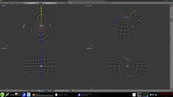 a link to a zip on my g-drive 67p.8-21-2014Mesh.zip - 1.8 meg with a 4k texture https://googledrive.com/host/0B6ZYAd08tZL-V...21-2014Mesh.zip |
|
|
|
|
Aug 17 2014, 05:33 AM
Post
#50
|
|
|
Solar System Cartographer Group: Members Posts: 10166 Joined: 5-April 05 From: Canada Member No.: 227 |
Re - mapping the lobes separately - it's an interesting idea and I would welcome any efforts along those lines. As I said in an earlier post, there's no one best way to do it, and we need many efforts to tackle this problem in different ways. But right now I think we should wait for a more detailed shape model and more images.
Phil -------------------- ... because the Solar System ain't gonna map itself.
Also to be found posting similar content on https://mastodon.social/@PhilStooke Maps for download (free PD: https://upload.wikimedia.org/wikipedia/comm...Cartography.pdf NOTE: everything created by me which I post on UMSF is considered to be in the public domain (NOT CC, public domain) |
|
|
|
|
Aug 20 2014, 10:26 PM
Post
#51
|
|
|
Member Group: Members Posts: 890 Joined: 18-November 08 Member No.: 4489 |
still working on this , just an early preview
I was able to extract a pointcloud from the gif animation http://blogs.esa.int/rosetta/2014/07/28/up...et-shape-model/ needs cleaning and meshing and is only a rough draft .... Phils map from post 188 http://www.unmannedspaceflight.com/index.p...st&p=212119 as expected there is a LOT of distortion |
|
|
|
|
Aug 22 2014, 03:39 AM
Post
#52
|
|
|
Solar System Cartographer Group: Members Posts: 10166 Joined: 5-April 05 From: Canada Member No.: 227 |
JohnVV wrote:
I was able to extract a pointcloud from the gif animation ------- needs cleaning and meshing and is only a rough draft .... Phils map from post 188 -------- as expected there is a LOT of distortion Wow! Considering how I put that thing together, I'm amazed how well the rendering worked out. Well done! Phil -------------------- ... because the Solar System ain't gonna map itself.
Also to be found posting similar content on https://mastodon.social/@PhilStooke Maps for download (free PD: https://upload.wikimedia.org/wikipedia/comm...Cartography.pdf NOTE: everything created by me which I post on UMSF is considered to be in the public domain (NOT CC, public domain) |
|
|
|
|
Aug 22 2014, 03:50 AM
Post
#53
|
|
|
Member Group: Members Posts: 890 Joined: 18-November 08 Member No.: 4489 |
phil
there is a zip with a obj mesh in it here https://googledrive.com/host/0B6ZYAd08tZL-V...21-2014Mesh.zip i have 0 long on the flat "base" and 180 on the top of the "head" it would be nice if the ESA would release there mesh ... |
|
|
|
|
Aug 22 2014, 02:13 PM
Post
#54
|
|
|
Member Group: Members Posts: 107 Joined: 1-August 14 Member No.: 7227 |
QUOTE (JohnVV @ Aug 17 2014, 04:55 AM) this gif animation ( pre orbit data ) http://scitechdaily.com/images/New-3D-View...setta-Comet.gif I have been able to get a ??? fair pointcloud out of the gif -- view in meshlab that is then meshed - in meshlab and cleaned up in blender Do you explain somewhere the method you used to get the meshed version from pointcloud version? I'd like to print a 3d-model of Pathfinder landing site (remember it?), but there are so many holes in the 3d data I found (a 20 years old VRML model...) that it's impossible to fill them up by hand. |
|
|
|
|
Aug 22 2014, 04:07 PM
Post
#55
|
|
 Member Group: Members Posts: 241 Joined: 22-August 05 From: Stockholm Sweden Member No.: 468 |
I'm playing around making a highresolution 3D representation of Comet 67P/Churyumov-Gerasimenko using a hybrid stereo correlation/shape from shading approach...
Take a look: http://mattias.malmer.nu/wp-content/upload...683D8388A36.mov |
|
|
|
|
Aug 22 2014, 05:50 PM
Post
#56
|
|
|
Member Group: Members Posts: 890 Joined: 18-November 08 Member No.: 4489 |
QUOTE Do you explain somewhere the method you used to get the meshed version from pointcloud version? I'd like to print a 3d-model of Pathfinder landing site (remember it?), but there are so many holes in the 3d data I found (a 20 years old VRML model...) that it's impossible to fill them up by hand. this thread is not the place for that i will post an explanation in the imaging processing but very basically 1) used "bundler-sfm" 2) used meshlab 3) then minor correcting in Blender |
|
|
|
|
Aug 23 2014, 01:35 AM
Post
#57
|
|
|
Member Group: Members Posts: 890 Joined: 18-November 08 Member No.: 4489 |
QUOTE (Malmer @ Aug 22 2014, 12:07 PM) I'm playing around making a highresolution 3D representation of Comet 67P/Churyumov-Gerasimenko using a hybrid stereo correlation/shape from shading approach... Take a look: http://mattias.malmer.nu/wp-content/upload...683D8388A36.mov nice vid i take it that is from the red/blue image release as Phil has posted mapping is going to be a pain do to the second sphere on top that makes a HIDDEN area from using a simple-cylindrical map 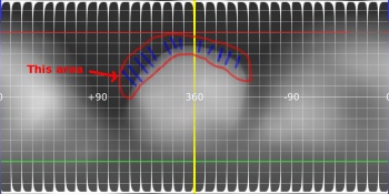
|
|
|
|
|
Aug 23 2014, 06:42 AM
Post
#58
|
|
|
Member Group: Members Posts: 241 Joined: 22-August 05 From: Stockholm Sweden Member No.: 468 |
QUOTE (JohnVV @ Aug 23 2014, 03:35 AM) nice vid i take it that is from the red/blue image release as Phil has posted mapping is going to be a pain do to the second sphere on top that makes a HIDDEN area from using a simple-cylindrical map Yes. I used the a and b images from that release. Well spotted! I can get very high resolution depth data from that pair. I used that pair as a quick test because it was easy to get it to work. I think limiting one self to using a simple cylindrical map for a concave object is inheritly wrong. What to do if you come across something with a higher genus topology. (Like a toroid or double toroid) then you would always have multiple overlaps. I like the idea of using multiple local cylindrical maps like mentioned earlier. |
|
|
|
|
Aug 23 2014, 02:37 PM
Post
#59
|
|
|
Solar System Cartographer Group: Members Posts: 10166 Joined: 5-April 05 From: Canada Member No.: 227 |
Hi Malmer - cartographers have already discussed these issues, so nobody is limiting anything to cylindrical maps. But the standard cylindrical maps are useful in many cases despite bad distortions because they are easily imported into common visualization software.
As an example, a toroidal world - like a comet nucleus with a vent burned right through it - could be mapped onto a plane using two dimensions, the azimuth around the ring itself and the azimuth around the cross-section (if you see what I mean) - two perpendicular azimuth dimensions mapped into a rectangle. It could also be mapped in azimuthal projections as the top and bottom faces, each one a circle with a hole in the middle. A Pretzel world - multiple piercings, a sort of hipster comet - could be done in more complex variations of the same ideas. Even cylindrical mapping can be done differently - especially as a transverse cylindrical projection where, for instance, an extremely elongated object like Eros can be surrounded by a cylinder whose long axis coincides with the object's long axis (instead of the rotation axis). Only the outer ends don't get mapped well like that, and they are done on small separate maps, as we often do polar maps in addition to a cylindrical Mercator projection. Separate maps of different areas are fine - we do it all the time on Earth after all - but they don't solve the issue of making one global map. Phil -------------------- ... because the Solar System ain't gonna map itself.
Also to be found posting similar content on https://mastodon.social/@PhilStooke Maps for download (free PD: https://upload.wikimedia.org/wikipedia/comm...Cartography.pdf NOTE: everything created by me which I post on UMSF is considered to be in the public domain (NOT CC, public domain) |
|
|
|
|
Aug 23 2014, 05:36 PM
Post
#60
|
|
|
Member Group: Members Posts: 241 Joined: 22-August 05 From: Stockholm Sweden Member No.: 468 |
For my own selfish purposes I will probably use some kind of LSCM unwrap to have resonably distortionfree and areapreserving representation.
|
|
|
|
|
Aug 23 2014, 10:06 PM
Post
#61
|
|
|
Member Group: Members Posts: 107 Joined: 1-August 14 Member No.: 7227 |
QUOTE (Malmer @ Aug 22 2014, 04:07 PM) I'm playing around making a highresolution 3D representation of Comet 67P/Churyumov-Gerasimenko using a hybrid stereo correlation/shape from shading approach... Take a look: http://mattias.malmer.nu/wp-content/upload...683D8388A36.mov Simply amazing! Are you also able to obtain a 3d STL model from those data? |
|
|
|
|
Aug 23 2014, 10:42 PM
Post
#62
|
|
|
Member Group: Members Posts: 241 Joined: 22-August 05 From: Stockholm Sweden Member No.: 468 |
QUOTE (mcgyver @ Aug 24 2014, 12:06 AM) Simply amazing! Are you also able to obtain a 3d STL model from those data? As it is now it is just a heightfield. It is just a quick proof of concept. I am going to use it to build a full shapemodel. |
|
|
|
|
Aug 24 2014, 10:07 AM
Post
#63
|
|
 Member Group: Members Posts: 648 Joined: 9-May 05 From: Subotica Member No.: 384 |
QUOTE (Malmer @ Aug 24 2014, 12:42 AM) I am going to use it to build a full shapemodel. WOW!!!! That's amazing!!! Awesome!!!!  While you build full model can you upload some more of the so far finished stuff....perhaps youtube??? -------------------- The scientist does not study nature because it is useful; he studies it because he delights in it, and he delights in it because it is beautiful.
Jules H. Poincare My "Astrophotos" gallery on flickr... |
|
|
|
|
Aug 25 2014, 10:42 AM
Post
#64
|
|
|
Member Group: Members Posts: 796 Joined: 27-February 08 From: Heart of Europe Member No.: 4057 |
QUOTE (wildespace @ Aug 16 2014, 09:54 AM) I have seen members here mention generating synthetic "in-between" frames from two images, so this is a callout for someone to hopefully generate a bunch of frames between the two fantastic OSIRIS images that made up that 3D view: http://blogs.esa.int/rosetta/2014/08/14/comet-67pc-g-in-3d/ The generated frames could be used to create a more "comfortable" anaglyph, or even an animation of the comet's rotation. It's possible (and Gerald already did this) but it's complicated by the shape of 67P and it's very time consuming job especially in case of rotation animation (which is possible thanks to the NavCam images). My guess is at least one hundred control points for every pair of images. For whole animation (one revolution) it's 1300-1500 control points. QUOTE (Malmer @ Aug 22 2014, 06:07 PM) I'm playing around making a highresolution 3D representation of Comet 67P/Churyumov-Gerasimenko using a hybrid stereo correlation/shape from shading approach... Take a look: http://mattias.malmer.nu/wp-content/upload...683D8388A36.mov It looks very impressive! It reminds me some works from the former(?) UMSF member who did 3D images from HiRISE cameras by shape-from-shading method. -------------------- |
|
|
|
|
Aug 25 2014, 12:08 PM
Post
#65
|
|
|
Senior Member Group: Members Posts: 2346 Joined: 7-December 12 Member No.: 6780 |
QUOTE (machi @ Aug 25 2014, 12:42 PM) ... it's very time consuming job ... My guess is at least one hundred control points for every pair of images... By automated matching of 256x256 = 65536 (overlapping) small tiles, and storing the respective displacements, I've tried to get this somehow managed. But areas with few features, e.g. large shadows or very smooth patches, are hard to match, and result in very noisy parts, despite noise filtering. Some features aren't visible in both images, so again hard to match. Here a visualization of such a displacement map:  The displacement map can then be used to generate a radius map (kind of a depth map), provided some telemetry data are known or estimated:  From this, a 3d-mesh could be generated. (But the quality of the above map isn't too convincing.) I've used the displacement map to generate the interpolated frames. (Credit for the underlying images, used to generate the above maps: ESA / Rosetta / MPS for OSIRIS Team MPS / UPD / LAM / IAA / SSO / INTA / UPM / DASP / IDA) |
|
|
|
|
Sep 2 2014, 11:41 PM
Post
#66
|
|
|
Member Group: Members Posts: 890 Joined: 18-November 08 Member No.: 4489 |
QUOTE t would be interesting to see a map of where "down" is in the different surface areas of the comet. down in the -- north up and south down --- a repost from a different forum the bottom two images in the bottom right image been working on mapping the esa jpg images to a updated mesh -- not looking good YET a 10 deg grid test map then warped to the mesh -- this is SCARY ( as in Oct. 31 scary ) then just the updated mesh and esa images from aug. 7 and 15  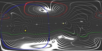  
|
|
|
|
|
Sep 3 2014, 12:42 AM
Post
#67
|
|
|
Senior Member Group: Members Posts: 1074 Joined: 21-September 07 From: Québec, Canada Member No.: 3908 |
What I would like to see is an image of the comet surrounded with short arrows pointing in the "down" direction.
|
|
|
|
|
Sep 3 2014, 01:08 AM
Post
#68
|
|
|
Member Group: Members Posts: 890 Joined: 18-November 08 Member No.: 4489 |
with "Down as the direction of the SouthPole
a few images   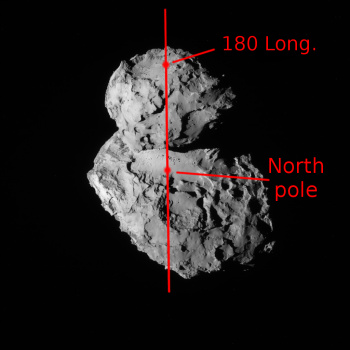   Navcam from the 14,15,20 and two images of my mesh in blender Copyright: ESA/Rosetta/NAVCAM and me - John vanvliet a DEM from the mesh i am using the center is 0 long / 0 lat -180 to 180 
|
|
|
|
|
Sep 3 2014, 01:20 AM
Post
#69
|
|
|
Member Group: Members Posts: 267 Joined: 5-February 06 Member No.: 675 |
QUOTE (charborob @ Sep 2 2014, 07:42 PM) What I would like to see is an image of the comet surrounded with short arrows pointing in the "down" direction. A similar result would be obtained by color coding a map of the comet to show height in reference to the "geoid. The colors would quickly show which regions of the comet were uphill or downhill from each other. Of course, the shape of 67P C-G's geoid will be interesting in itself and something of a chore to compute. |
|
|
|
|
Sep 3 2014, 11:14 AM
Post
#70
|
|
|
Junior Member Group: Members Posts: 40 Joined: 28-July 07 Member No.: 2984 |
QUOTE (ngunn @ Sep 2 2014, 01:16 PM) You made that statement before, but the opposite is in fact the case. The midpoint is the place on the comet's surface where gravitational potential is lowest... If you were to take two spherical objects and connect them with a stick (or have them orbit each other) then the low potential point would not be at the midpoint between them, I.e., at the center of mass of the two body system. There would be two low points, at the center of mass of each of the two spheres. The midpoint of the system is a saddle point, with a higher potential than either of the two centers. |
|
|
|
|
Sep 3 2014, 11:49 AM
Post
#71
|
|
|
Member Group: Members Posts: 241 Joined: 22-August 05 From: Stockholm Sweden Member No.: 468 |
QUOTE (JohnVV @ Sep 3 2014, 01:41 AM) down in the -- north up and south down --- a repost from a different forum the bottom two images in the bottom right image been working on mapping the esa jpg images to a updated mesh -- not looking good YET a 10 deg grid test map then warped to the mesh -- this is SCARY ( as in Oct. 31 scary ) then just the updated mesh and esa images from aug. 7 and 15 Is that your own shapemodel or is it something ESA have made that is in the public domain? Im working on building my own. but I would like to have another stereo pair from osiris before i continue in ernest. (i want to make an ultra high density model) I have reverseengineered all the spacecraft positions relative to the comet for all pictures up until now but i have no real coordinate system yet. Is there a consensus northpole and a southpole and a prime meridian that i can use to build that? Just points on the surface would help  edit: oh.. you just posted those pictures... where did you get that information? |
|
|
|
|
Sep 3 2014, 12:07 PM
Post
#72
|
|
|
Senior Member Group: Members Posts: 3516 Joined: 4-November 05 From: North Wales Member No.: 542 |
QUOTE (Y Bar Ranch @ Sep 3 2014, 12:14 PM) If you were to take two spherical objects and connect them with a stick (or have them orbit each other) then the low potential point would not be at the midpoint between them, I.e., at the center of mass of the two body system. There would be two low points, at the center of mass of each of the two spheres. The midpoint of the system is a saddle point, with a higher potential than either of the two centers. That's absolutely correct, but materials on the comet surface cannot fall towards either of the two centres. They are constrained to move on or above the surface. That being so, the neck is the lowest potential location they can migrate to. |
|
|
|
|
Sep 3 2014, 05:14 PM
Post
#73
|
|
|
Member Group: Members Posts: 890 Joined: 18-November 08 Member No.: 4489 |
QUOTE Is that your own shapemodel or is it something ESA have made that is in the public domain? no it is all mine i used motion to make a "point cloud" from two videos then meshed it and just finished a rough edit i am about to add details from the images using "shape from shade" an old bit of code from a siggraph paper "mini_sfs" and a newer phd paper and code http://code.google.com/p/hyperion-cv/ i have NOT uploaded version TWO yet version 1 is here https://googledrive.com/host/0B6ZYAd08tZL-V...21-2014Mesh.zip --- VERSION 2 is here "67P.09.03.2014.zip" https://googledrive.com/host/0B6ZYAd08tZL-V....09.03.2014.zip |
|
|
|
|
Sep 3 2014, 06:05 PM
Post
#74
|
|
|
Solar System Cartographer Group: Members Posts: 10166 Joined: 5-April 05 From: Canada Member No.: 227 |
I am very impressed by this, John! Looking forward to seeing it evolve.
Phil -------------------- ... because the Solar System ain't gonna map itself.
Also to be found posting similar content on https://mastodon.social/@PhilStooke Maps for download (free PD: https://upload.wikimedia.org/wikipedia/comm...Cartography.pdf NOTE: everything created by me which I post on UMSF is considered to be in the public domain (NOT CC, public domain) |
|
|
|
|
Sep 3 2014, 06:33 PM
Post
#75
|
|
|
Junior Member Group: Members Posts: 40 Joined: 28-July 07 Member No.: 2984 |
QUOTE (ngunn @ Sep 3 2014, 08:07 AM) That's absolutely correct, but materials on the comet surface cannot fall towards either of the two centres. They are constrained to move on or above the surface. That being so, the neck is the lowest potential location they can migrate to. OK, here's my super simple comet model. Two spheres, radius 2 and radius 1, connected by a cylinder neck of length = 1 and radius = 1/2. Streamlines are down the gradient of the potential. Contours are the potential. YMMV on accuracy. I can improve it and generate the 3D field with some more accurate estimations of the lobes and neck. Fun to fiddle with. 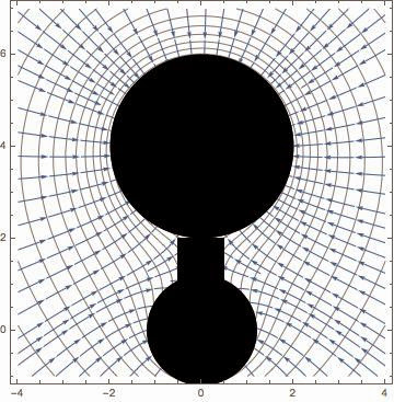 |
|
|
|
|
Sep 3 2014, 07:19 PM
Post
#76
|
|
|
Senior Member Group: Members Posts: 3516 Joined: 4-November 05 From: North Wales Member No.: 542 |
QUOTE (Y Bar Ranch @ Sep 3 2014, 07:33 PM) super simple comet model Excellent! Now focus on the force vectors just at the points where they intersect the surface of the 'comet' and imagine them resolved into normal and tangential components. Chuck out the normal components and map the tangential ones as arrows drawn on the 'cometary' surface. You would then have a first approximation local slope direction map as requested by Mercure and charborob a few posts up. EDIT: now at post 227 in the other Rosetta thread, Early Orbital Operations. EDIT: Interestingly, your diagram already shows that the steepest gradient (angle between force vector and the normal) is to be found on the inner side of the smaller lobe, exactly the place on the actual comet where there are features tentatively attributed to a landslip. |
|
|
|
|
Sep 3 2014, 08:54 PM
Post
#77
|
|
|
Member Group: Members Posts: 241 Joined: 22-August 05 From: Stockholm Sweden Member No.: 468 |
QUOTE (JohnVV @ Sep 3 2014, 07:14 PM) no it is all mine i used motion to make a "point cloud" from two videos Ah, you used ESAs videos of their shapemodel and reverseengineered it. Clever. I'm just using the "raw" images to build my own. (I want to make it from scratch just as an exercise in image processing) I'm using a very simple shape from shading algorithm that i made myself to add the details. (Would make your skin crawl) The race is on |
|
|
|
|
Sep 3 2014, 09:09 PM
Post
#78
|
|
|
Junior Member Group: Members Posts: 40 Joined: 28-July 07 Member No.: 2984 |
I'd be interested in grabbing whatever you guys come up with. Point cloud is OK. Then I can play with gravity modeling. |
|
|
|
|
Sep 3 2014, 09:48 PM
Post
#79
|
|
|
Member Group: Members Posts: 241 Joined: 22-August 05 From: Stockholm Sweden Member No.: 468 |
Will post as soon as it is resonably correct.
|
|
|
|
|
Sep 3 2014, 09:50 PM
Post
#80
|
|
|
Member Group: Members Posts: 890 Joined: 18-November 08 Member No.: 4489 |
QUOTE I'd be interested in grabbing whatever you guys come up with. Point cloud is OK. Then I can play with gravity modeling. i just zipped up a the mash as of today -- a low res 1.3 meg .obj file the zip contains a map-grid uv mapped https://googledrive.com/host/0B6ZYAd08tZL-V....09.03.2014.zip |
|
|
|
|
Sep 3 2014, 10:32 PM
Post
#81
|
|
|
Member Group: Members Posts: 241 Joined: 22-August 05 From: Stockholm Sweden Member No.: 468 |
QUOTE (JohnVV @ Sep 3 2014, 11:50 PM) i just zipped up a the mash as of today -- a low res 1.3 meg .obj file the zip contains a map-grid uv mapped https://googledrive.com/host/0B6ZYAd08tZL-V....09.03.2014.zip I will use it to line up mine so that we work in the same coordinate system. (Just noticed that I made my 100th post and became a "Member" today after nine years. I guess I read a lot and post very little...) |
|
|
|
|
Sep 3 2014, 10:50 PM
Post
#82
|
|
|
Senior Member Group: Members Posts: 2346 Joined: 7-December 12 Member No.: 6780 |
QUOTE (Y Bar Ranch @ Sep 3 2014, 08:33 PM) OK, here's my super simple comet model... Does the model already contain the shift due to rotation? |
|
|
|
|
Sep 3 2014, 10:52 PM
Post
#83
|
|
|
Junior Member Group: Members Posts: 88 Joined: 8-May 14 Member No.: 7185 |
QUOTE (ngunn @ Sep 3 2014, 08:19 PM) map the tangential ones as arrows drawn on the 'cometary' surface. Yes, I also think that would be the best visualisation, with arrow length indicating gravitational pull. Or perhaps visualize it as 'stubs' or 'sticks' on the surface of the model, with tilt and length of the stubs indicating gravitational direction and pull. Such a visualization would also be interesting seen in conjunction with outgassing, to see if hotspots correlate with areas of relatively weak gravity or not. Y Bar Ranch, very interesting first stab at a visualisation, thank you for doing it. |
|
|
|
|
Sep 4 2014, 02:59 AM
Post
#84
|
|
|
Member Group: Members Posts: 148 Joined: 9-August 11 From: Mason, TX Member No.: 6108 |
Another way that readers might better associate with the upcoming Philae landing process would be to have a set of points positioned above each candidate landing site about 10km off the surface with a downward pointing arrow representing the direction and relative strength of attraction on each such 100kilogram point. Then we could appreciate the unique issues with being positioned correctly at release for a descent into the intended spot. Ignoring the orbital velocity, just the "down" vector at those locations would be interesting to see. Is this possible, and even useful for others?
-------------------- --
Don |
|
|
|
|
Sep 4 2014, 12:12 PM
Post
#85
|
|
|
Junior Member Group: Members Posts: 40 Joined: 28-July 07 Member No.: 2984 |
QUOTE (Gerald @ Sep 3 2014, 05:50 PM) Does the model already contain the shift due to rotation? No...just a simple malformed dumbbell right now |
|
|
|
|
Sep 4 2014, 06:50 PM
Post
#86
|
|
 Member Group: Members Posts: 146 Joined: 23-August 06 From: Vriezenveen, Netherlands Member No.: 1067 |
QUOTE (JohnVV @ Sep 3 2014, 11:50 PM) i just zipped up a the mash as of today -- a low res 1.3 meg .obj file the zip contains a map-grid uv mapped https://googledrive.com/host/0B6ZYAd08tZL-V....09.03.2014.zip Thanks! Let's see if I can convert it to 3ds and then to CMOD
|
|
|
|
|
Sep 4 2014, 07:08 PM
Post
#87
|
|
|
Member Group: Members Posts: 107 Joined: 1-August 14 Member No.: 7227 |
QUOTE (CAP-Team @ Sep 4 2014, 06:50 PM) Thanks! Let's see if I can convert it to 3ds and then to CMOD What about STL? Is it possible? |
|
|
|
|
Sep 4 2014, 08:11 PM
Post
#88
|
|
|
Member Group: Members Posts: 890 Joined: 18-November 08 Member No.: 4489 |
3ds to cmod is rather easy
now the plugin is for the OLD!!! blender python API so you need to use Blender 2.49b and building the tool " cmodview" from the celestia SVN source will save a ASCII mesh to a binary mesh also my mesh IS NOT a "3ds " it is a Alias Wavefront format that is almost identical to the PDS vertex shape file |
|
|
|
|
Sep 4 2014, 08:33 PM
Post
#89
|
|
|
Member Group: Members Posts: 241 Joined: 22-August 05 From: Stockholm Sweden Member No.: 468 |
QUOTE (JohnVV @ Sep 4 2014, 10:11 PM) 3ds to cmod is rather easy now the plugin is for the OLD!!! blender python API so you need to use Blender 2.49b and building the tool " cmodview" from the celestia SVN source will save a ASCII mesh to a binary mesh also my mesh IS NOT a "3ds " it is a Alias Wavefront format that is almost identical to the PDS vertex shape file The 3ds format is really not much fun. The 3DS format does not support more than one UV coordinate per vertex. You will get problems along UV seams |
|
|
|
|
Sep 4 2014, 09:09 PM
Post
#90
|
|
|
Founder Group: Chairman Posts: 14432 Joined: 8-February 04 Member No.: 1 |
QUOTE (mcgyver @ Sep 4 2014, 12:08 PM) What about STL? Is it possible? Download and install Blender ( http://www.blender.org/ ) Import OBJ Export STL. Done. (Caution - you will not want to try and print an object like this on a 3D printer as-is. You will need to bifurcate it into hemispheres - such as I've done for other small bodies like Eros, Itokawa and Vesta http://nasa3d.arc.nasa.gov/search/ellison/model ) |
|
|
|
|
Sep 4 2014, 10:07 PM
Post
#91
|
|
|
Senior Member Group: Members Posts: 2346 Joined: 7-December 12 Member No.: 6780 |
Some qualitative sensitivity analysis of trajectories to a rotating contact binary starting from an equatorial position about 10km from the center.
This gif shows a 10 and a 100 trajectories version to a binary consisting of two spheres, radii 1250 and 750m, density 1000 kg/m³ (to get about 1e13kg with this geometry), rotation period 12.4 hours; initial tangential velocity of the lander is zero (relative to the inertial frame at rest relative to the center), initial radial velocity 0.5 m/s:  The trajectories are shown in a reference frame, rotating with the binary. Only the region on one side of the neck isn't accessible, even in theory. High sensitivity to initial radial velocity of the lander, in 0.1 m/s steps from 0.0 to 0.5 m/s:  and to initial tangential velocity (0.0 and 0.1 m/s):  Sensitivity to the comet's mass is higher for low initial radial velocity (0.1 m/s) of the lander  than for higher initial radial velocity (0.4 m/s); this may have been expected:  (assuming no relevant programming flaws) |
|
|
|
|
Sep 4 2014, 10:23 PM
Post
#92
|
|
|
Senior Member Group: Members Posts: 4247 Joined: 17-January 05 Member No.: 152 |
Nice. So did you chose the rotation axis to be perpendicular to the line joining the two centres? I guess that crudely corresponds to C-G.
|
|
|
|
|
Sep 4 2014, 10:30 PM
Post
#93
|
|
|
Senior Member Group: Members Posts: 2346 Joined: 7-December 12 Member No.: 6780 |
Yes.
|
|
|
|
|
Sep 4 2014, 11:05 PM
Post
#94
|
|
|
Member Group: Members Posts: 241 Joined: 22-August 05 From: Stockholm Sweden Member No.: 468 |
QUOTE (JohnVV @ Sep 3 2014, 11:50 PM) i just zipped up a the mash as of today -- a low res 1.3 meg .obj file the zip contains a map-grid uv mapped https://googledrive.com/host/0B6ZYAd08tZL-V....09.03.2014.zip I cant really get the scale right. Is it an arbitrary scale on your model? |
|
|
|
|
Sep 5 2014, 06:47 PM
Post
#95
|
|
|
Member Group: Members Posts: 890 Joined: 18-November 08 Member No.: 4489 |
Blender is not a "cad/cam" set-up
so the dimensions are NOT in Meters or KM also depending on what software you are using to import the mesh , it might be big or small but the proportions will not change |
|
|
|
|
Sep 5 2014, 07:04 PM
Post
#96
|
|
|
Member Group: Members Posts: 241 Joined: 22-August 05 From: Stockholm Sweden Member No.: 468 |
QUOTE (JohnVV @ Sep 5 2014, 08:47 PM) Blender is not a "cad/cam" set-up so the dimensions are NOT in Meters or KM also depending on what software you are using to import the mesh , it might be big or small but the proportions will not change I'm using imagemodeler to generate a relatively sparse pointcloud. I'm manually placing all the markers on each image to make sure that there is maximum precision in the camera solve. I'm calibrating the scale to match the spacecraft distances that ESA give for the images. I will drop that data into Nuke to generate a dense cloud by stereo correlation. Then I will add the last bit of detail using SFS. There will probably be a bit of 3dsmax aswell. |
|
|
|
|
Sep 16 2014, 05:44 AM
Post
#97
|
|
|
Member Group: Members Posts: 890 Joined: 18-November 08 Member No.: 4489 |
well the landing site is near 190 long and just a bit north about 15 north
some pics in 3D of the area and a DEM ( using SFS)    there is a zip of the mesh ( not 100% accurate to the comet ,just an approximation ) https://googledrive.com/host/0B6ZYAd08tZL-V...LandingSite.zip PhilaeLandingSite.zip │ ├── PhilaeLandingSite.mtl │ ├── PhilaeLandingSite.obj │ ├── Philae_s_primary_landing_site1.png │ ├── sfs_DEM.32bitFloat.tiff │ └── sfs_DEM.8bit.png the heightmap is from this image http://www.esa.int/spaceinimages/Images/20...ry_landing_site using Shape From Shade |
|
|
|
|
Sep 24 2014, 12:43 AM
Post
#98
|
|
|
Member Group: Members Posts: 890 Joined: 18-November 08 Member No.: 4489 |
with the few images and the video
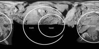
"Possible landing sites on _ Mögliche Landestellen auf Churyumov-Gerasimenko - YouTube [720p].mp4 " can anyone add a bit more pinpoint area for a few locations 0 long 180 long 90 North prime meridian as far as i can tell they are someplace in the red circles below    
|
|
|
|
|
Sep 24 2014, 01:17 AM
Post
#99
|
|
|
Member Group: Members Posts: 241 Joined: 22-August 05 From: Stockholm Sweden Member No.: 468 |
QUOTE (JohnVV @ Sep 24 2014, 02:43 AM) with the few images and the video "Possible landing sites on _ Mögliche Landestellen auf Churyumov-Gerasimenko - YouTube [720p].mp4 " can anyone add a bit more pinpoint area for a few locations 0 long 180 long 90 North prime meridian as far as i can tell they are someplace in the red circles below I really want that data aswell... (and an exact distance between north south wouldn't hurt either) |
|
|
|
|
Sep 24 2014, 02:25 AM
Post
#100
|
|
|
Member Group: Members Posts: 890 Joined: 18-November 08 Member No.: 4489 |
from the image
"Comet_on_16_August_c.jpg" has 180 x 0 and 90N in it and a few other images it looks like one can make a line from some boulders in the crater to the N pole  |
|
|
|
 |

|
Lo-Fi Version | Time is now: 23rd May 2024 - 10:30 PM |
|
RULES AND GUIDELINES Please read the Forum Rules and Guidelines before posting. IMAGE COPYRIGHT |
OPINIONS AND MODERATION Opinions expressed on UnmannedSpaceflight.com are those of the individual posters and do not necessarily reflect the opinions of UnmannedSpaceflight.com or The Planetary Society. The all-volunteer UnmannedSpaceflight.com moderation team is wholly independent of The Planetary Society. The Planetary Society has no influence over decisions made by the UnmannedSpaceflight.com moderators. |
SUPPORT THE FORUM Unmannedspaceflight.com is funded by the Planetary Society. Please consider supporting our work and many other projects by donating to the Society or becoming a member. |
|