

3D shape, cartography, and geoid of Comet 67P C-G |

  |
3D shape, cartography, and geoid of Comet 67P C-G |
 Aug 23 2014, 10:06 PM Aug 23 2014, 10:06 PM
Post
#61
|
|
|
Member  Group: Members Posts: 107 Joined: 1-August 14 Member No.: 7227 |
QUOTE (Malmer @ Aug 22 2014, 04:07 PM)  I'm playing around making a highresolution 3D representation of Comet 67P/Churyumov-Gerasimenko using a hybrid stereo correlation/shape from shading approach... Take a look: http://mattias.malmer.nu/wp-content/upload...683D8388A36.mov Simply amazing! Are you also able to obtain a 3d STL model from those data? |
 |
 
|
|
Aug 23 2014, 10:42 PM
Post
#62
|
|
 Member Group: Members Posts: 241 Joined: 22-August 05 From: Stockholm Sweden Member No.: 468 |
QUOTE (mcgyver @ Aug 24 2014, 12:06 AM) Simply amazing! Are you also able to obtain a 3d STL model from those data? As it is now it is just a heightfield. It is just a quick proof of concept. I am going to use it to build a full shapemodel. |
|
|
|
|
Aug 24 2014, 10:07 AM
Post
#63
|
|
 Member Group: Members Posts: 648 Joined: 9-May 05 From: Subotica Member No.: 384 |
QUOTE (Malmer @ Aug 24 2014, 12:42 AM) I am going to use it to build a full shapemodel. WOW!!!! That's amazing!!! Awesome!!!!  While you build full model can you upload some more of the so far finished stuff....perhaps youtube??? -------------------- The scientist does not study nature because it is useful; he studies it because he delights in it, and he delights in it because it is beautiful.
Jules H. Poincare My "Astrophotos" gallery on flickr... |
|
|
|
|
Aug 25 2014, 10:42 AM
Post
#64
|
|
 Member Group: Members Posts: 796 Joined: 27-February 08 From: Heart of Europe Member No.: 4057 |
QUOTE (wildespace @ Aug 16 2014, 09:54 AM) I have seen members here mention generating synthetic "in-between" frames from two images, so this is a callout for someone to hopefully generate a bunch of frames between the two fantastic OSIRIS images that made up that 3D view: http://blogs.esa.int/rosetta/2014/08/14/comet-67pc-g-in-3d/ The generated frames could be used to create a more "comfortable" anaglyph, or even an animation of the comet's rotation. It's possible (and Gerald already did this) but it's complicated by the shape of 67P and it's very time consuming job especially in case of rotation animation (which is possible thanks to the NavCam images). My guess is at least one hundred control points for every pair of images. For whole animation (one revolution) it's 1300-1500 control points. QUOTE (Malmer @ Aug 22 2014, 06:07 PM) I'm playing around making a highresolution 3D representation of Comet 67P/Churyumov-Gerasimenko using a hybrid stereo correlation/shape from shading approach... Take a look: http://mattias.malmer.nu/wp-content/upload...683D8388A36.mov It looks very impressive! It reminds me some works from the former(?) UMSF member who did 3D images from HiRISE cameras by shape-from-shading method. -------------------- |
|
|
|
|
Aug 25 2014, 12:08 PM
Post
#65
|
|
|
Senior Member Group: Members Posts: 2346 Joined: 7-December 12 Member No.: 6780 |
QUOTE (machi @ Aug 25 2014, 12:42 PM) ... it's very time consuming job ... My guess is at least one hundred control points for every pair of images... By automated matching of 256x256 = 65536 (overlapping) small tiles, and storing the respective displacements, I've tried to get this somehow managed. But areas with few features, e.g. large shadows or very smooth patches, are hard to match, and result in very noisy parts, despite noise filtering. Some features aren't visible in both images, so again hard to match. Here a visualization of such a displacement map:  The displacement map can then be used to generate a radius map (kind of a depth map), provided some telemetry data are known or estimated:  From this, a 3d-mesh could be generated. (But the quality of the above map isn't too convincing.) I've used the displacement map to generate the interpolated frames. (Credit for the underlying images, used to generate the above maps: ESA / Rosetta / MPS for OSIRIS Team MPS / UPD / LAM / IAA / SSO / INTA / UPM / DASP / IDA) |
|
|
|
|
Sep 2 2014, 11:41 PM
Post
#66
|
|
|
Member Group: Members Posts: 890 Joined: 18-November 08 Member No.: 4489 |
QUOTE t would be interesting to see a map of where "down" is in the different surface areas of the comet. down in the -- north up and south down --- a repost from a different forum the bottom two images in the bottom right image been working on mapping the esa jpg images to a updated mesh -- not looking good YET a 10 deg grid test map then warped to the mesh -- this is SCARY ( as in Oct. 31 scary ) then just the updated mesh and esa images from aug. 7 and 15  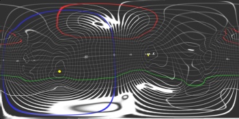  
|
|
|
|
|
Sep 3 2014, 12:42 AM
Post
#67
|
|
|
Senior Member Group: Members Posts: 1075 Joined: 21-September 07 From: Québec, Canada Member No.: 3908 |
What I would like to see is an image of the comet surrounded with short arrows pointing in the "down" direction.
|
|
|
|
|
Sep 3 2014, 01:08 AM
Post
#68
|
|
|
Member Group: Members Posts: 890 Joined: 18-November 08 Member No.: 4489 |
with "Down as the direction of the SouthPole
a few images   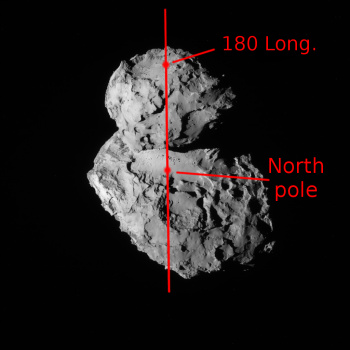   Navcam from the 14,15,20 and two images of my mesh in blender Copyright: ESA/Rosetta/NAVCAM and me - John vanvliet a DEM from the mesh i am using the center is 0 long / 0 lat -180 to 180 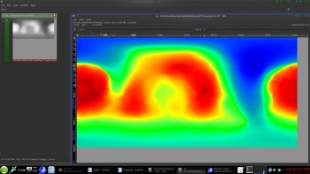
|
|
|
|
|
Sep 3 2014, 01:20 AM
Post
#69
|
|
 Member Group: Members Posts: 267 Joined: 5-February 06 Member No.: 675 |
QUOTE (charborob @ Sep 2 2014, 07:42 PM) What I would like to see is an image of the comet surrounded with short arrows pointing in the "down" direction. A similar result would be obtained by color coding a map of the comet to show height in reference to the "geoid. The colors would quickly show which regions of the comet were uphill or downhill from each other. Of course, the shape of 67P C-G's geoid will be interesting in itself and something of a chore to compute. |
|
|
|
|
Sep 3 2014, 11:14 AM
Post
#70
|
|
|
Junior Member Group: Members Posts: 40 Joined: 28-July 07 Member No.: 2984 |
QUOTE (ngunn @ Sep 2 2014, 01:16 PM) You made that statement before, but the opposite is in fact the case. The midpoint is the place on the comet's surface where gravitational potential is lowest... If you were to take two spherical objects and connect them with a stick (or have them orbit each other) then the low potential point would not be at the midpoint between them, I.e., at the center of mass of the two body system. There would be two low points, at the center of mass of each of the two spheres. The midpoint of the system is a saddle point, with a higher potential than either of the two centers. |
|
|
|
|
Sep 3 2014, 11:49 AM
Post
#71
|
|
|
Member Group: Members Posts: 241 Joined: 22-August 05 From: Stockholm Sweden Member No.: 468 |
QUOTE (JohnVV @ Sep 3 2014, 01:41 AM) down in the -- north up and south down --- a repost from a different forum the bottom two images in the bottom right image been working on mapping the esa jpg images to a updated mesh -- not looking good YET a 10 deg grid test map then warped to the mesh -- this is SCARY ( as in Oct. 31 scary ) then just the updated mesh and esa images from aug. 7 and 15 Is that your own shapemodel or is it something ESA have made that is in the public domain? Im working on building my own. but I would like to have another stereo pair from osiris before i continue in ernest. (i want to make an ultra high density model) I have reverseengineered all the spacecraft positions relative to the comet for all pictures up until now but i have no real coordinate system yet. Is there a consensus northpole and a southpole and a prime meridian that i can use to build that? Just points on the surface would help  edit: oh.. you just posted those pictures... where did you get that information? |
|
|
|
|
Sep 3 2014, 12:07 PM
Post
#72
|
|
|
Senior Member Group: Members Posts: 3516 Joined: 4-November 05 From: North Wales Member No.: 542 |
QUOTE (Y Bar Ranch @ Sep 3 2014, 12:14 PM) If you were to take two spherical objects and connect them with a stick (or have them orbit each other) then the low potential point would not be at the midpoint between them, I.e., at the center of mass of the two body system. There would be two low points, at the center of mass of each of the two spheres. The midpoint of the system is a saddle point, with a higher potential than either of the two centers. That's absolutely correct, but materials on the comet surface cannot fall towards either of the two centres. They are constrained to move on or above the surface. That being so, the neck is the lowest potential location they can migrate to. |
|
|
|
|
Sep 3 2014, 05:14 PM
Post
#73
|
|
|
Member Group: Members Posts: 890 Joined: 18-November 08 Member No.: 4489 |
QUOTE Is that your own shapemodel or is it something ESA have made that is in the public domain? no it is all mine i used motion to make a "point cloud" from two videos then meshed it and just finished a rough edit i am about to add details from the images using "shape from shade" an old bit of code from a siggraph paper "mini_sfs" and a newer phd paper and code http://code.google.com/p/hyperion-cv/ i have NOT uploaded version TWO yet version 1 is here https://googledrive.com/host/0B6ZYAd08tZL-V...21-2014Mesh.zip --- VERSION 2 is here "67P.09.03.2014.zip" https://googledrive.com/host/0B6ZYAd08tZL-V....09.03.2014.zip |
|
|
|
|
Sep 3 2014, 06:05 PM
Post
#74
|
|
|
Solar System Cartographer Group: Members Posts: 10226 Joined: 5-April 05 From: Canada Member No.: 227 |
I am very impressed by this, John! Looking forward to seeing it evolve.
Phil -------------------- ... because the Solar System ain't gonna map itself.
Also to be found posting similar content on https://mastodon.social/@PhilStooke Maps for download (free PDF: https://upload.wikimedia.org/wikipedia/comm...Cartography.pdf NOTE: everything created by me which I post on UMSF is considered to be in the public domain (NOT CC, public domain) |
|
|
|
|
Sep 3 2014, 06:33 PM
Post
#75
|
|
|
Junior Member Group: Members Posts: 40 Joined: 28-July 07 Member No.: 2984 |
QUOTE (ngunn @ Sep 3 2014, 08:07 AM) That's absolutely correct, but materials on the comet surface cannot fall towards either of the two centres. They are constrained to move on or above the surface. That being so, the neck is the lowest potential location they can migrate to. OK, here's my super simple comet model. Two spheres, radius 2 and radius 1, connected by a cylinder neck of length = 1 and radius = 1/2. Streamlines are down the gradient of the potential. Contours are the potential. YMMV on accuracy. I can improve it and generate the 3D field with some more accurate estimations of the lobes and neck. Fun to fiddle with. 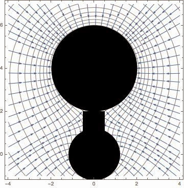 |
|
|
|
|

|
Lo-Fi Version | Time is now: 21st September 2024 - 08:49 PM |
|
RULES AND GUIDELINES Please read the Forum Rules and Guidelines before posting. IMAGE COPYRIGHT |
OPINIONS AND MODERATION Opinions expressed on UnmannedSpaceflight.com are those of the individual posters and do not necessarily reflect the opinions of UnmannedSpaceflight.com or The Planetary Society. The all-volunteer UnmannedSpaceflight.com moderation team is wholly independent of The Planetary Society. The Planetary Society has no influence over decisions made by the UnmannedSpaceflight.com moderators. |
SUPPORT THE FORUM Unmannedspaceflight.com is funded by the Planetary Society. Please consider supporting our work and many other projects by donating to the Society or becoming a member. |
|


